STM32的正交编码器模式读取编码器的角度数据和速度
https://v.youku.com/v_show/id_XNDQ3Mjc0OTQwMA==.html?spm=a2h3j.8428770.3416059.1
视频演示
编码器接口模式
选择编码器接口模式的方法是:
如果计数器只在TI2的边沿计数,则置TIMx_SMCR寄存器中的 SMS=001
;
如果只在TI1边沿计数,则置SMS=010;如果计数器同时在TI1和TI2边沿计数,则置SMS=011。
通过设置TIMx_CCER寄存器中的CC1P和CC2P位,可以选择TI1和TI2极性;如果需要,还可以 对输入滤波器编程。
两个输入TI1和
TI2
被用来作为增量编码器的接口。参看表73
,
假定计数器已经启动
(TIMx_CR1 寄存器中的CEN=1)
,则计数器由每次在
TI1FP1
或
TI2FP2
上的有效跳变驱动。
TI1FP1
和
TI2FP2 是TI1
和
TI2
在通过输入滤波器和极性控制后的信号;如果没有滤波和变相,则
TI1FP1=TI1
, TI2FP2=TI2。根据两个输入信号的跳变顺序,产生了计数脉冲和方向信号。依据两个输入信号 的跳变顺序,计数器向上或向下计数,同时硬件对TIMx_CR1
寄存器的
DIR
位进行相应的设置。
不管计数器是依靠TI1计数、依靠TI2计数或者同时依靠TI1和TI2计数,在任一输入端(TI1或者 TI2)的跳变都会重新计算DIR位。 编码器接口模式基本上相当于使用了一个带有方向选择的外部时钟。这意味着计数器只在0到 TIMx_ARR寄存器的自动装载值之间连续计数(根据方向,或是0到ARR计数,或是ARR到0计 数)。
所以在开始计数之前必须配置
TIMx_ARR
;同样,捕获器、比较器、预分频器、重复计数 器、触发输出特性等仍工作如常。编码器模式和外部时钟模式2
不兼容,因此不能同时操作。 在这个模式下,计数器依照增量编码器的速度和方向被自动的修改,因此计数器的内容始终指 示着编码器的位置。计数方向与相连的传感器旋转的方向对应。下表列出了所有可能的组合,
假设
TI1
和
TI2
不同时变换。
表
73
计数方向与编码器信号的关系
一个外部的增量编码器可以直接与
MCU
连接而不需要外部接口逻辑。但是,一般会使用比较器
将编码器的差动输出转换到数字信号,这大大增加了抗噪声干扰能力。编码器输出的第三个信
号表示机械零点,可以把它连接到一个外部中断输入并触发一个计数器复位。
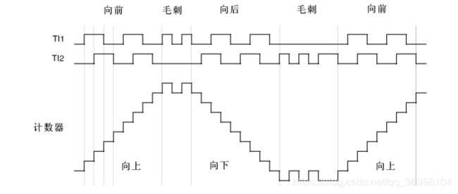
下图是一个计数器操作的实例,显示了计数信号的产生和方向控制。它还显示了当选择了双边
沿时,输入抖动是如何被抑制的;抖动可能会在传感器的位置靠近一个转换点时产生。在这个
例子中,我们假定配置如下:
●
CC1S=’01’ (TIMx_CCMR1
寄存器,
IC1FP1
映射到
TI1)
●
CC2S=’01’ (TIMx_CCMR2
寄存器,
IC2FP2
映射到
TI2)
●
CC1P=’0’ (TIMx_CCER
寄存器,
IC1FP1
不反相,
IC1FP1=TI1)
●
CC2P=’0’ (TIMx_CCER
寄存器,
IC2FP2
不反相,
IC2FP2=TI2)
●
SMS=’011’ (TIMx_SMCR
寄存器,所有的输入均在上升沿和下降沿有效
).
●
CEN=’1’ (TIMx_CR1
寄存器,计数器使能
)
(1)、stm32f407中定时器1、2、3、4、5、8提供编码器接口模式
(2)、可以对输入信号TI1,TI2进行滤波处理,数字滤波器由事件器组成,每N个事件才视为一个有效边沿,可以在TIMx_CCMR1、TIMx_CCMR2中的IC1F位域设置
(3)、stm32提供了单项计数(只能测速度)和双项计数模式(可测速度&方向),双项模式可以更好地消除毛刺干扰,一般使用双项模式
(2)、可以对输入信号TI1,TI2进行滤波处理,数字滤波器由事件器组成,每N个事件才视为一个有效边沿,可以在TIMx_CCMR1、TIMx_CCMR2中的IC1F位域设置
(3)、stm32提供了单项计数(只能测速度)和双项计数模式(可测速度&方向),双项模式可以更好地消除毛刺干扰,一般使用双项模式
TIM_EncoderInterfaceConfig(TIM2, TIM_EncoderMode_TI12,TIM_ICPolarity_Falling, TIM_ICPolarity_Falling);函数原型
/**
  * @brief  Configures the TIMx Encoder Interface.
  * @param  TIMx: where x can be  1, 2, 3, 4, 5 or 8 to select the TIM peripheral.
  * @param  TIM_EncoderMode: specifies the TIMx Encoder Mode.
  *   This parameter can be one of the following values:
  *     @arg TIM_EncoderMode_TI1: Counter counts on TI1FP1 edge depending on TI2FP2 level.
  *     @arg TIM_EncoderMode_TI2: Counter counts on TI2FP2 edge depending on TI1FP1 level.
  *     @arg TIM_EncoderMode_TI12: Counter counts on both TI1FP1 and TI2FP2 edges depending
  *                                on the level of the other input.
  * @param  TIM_IC1Polarity: specifies the IC1 Polarity
  *   This parameter can be one of the following values:
  *     @arg TIM_ICPolarity_Falling: IC Falling edge.
  *     @arg TIM_ICPolarity_Rising: IC Rising edge.
  * @param  TIM_IC2Polarity: specifies the IC2 Polarity
  *   This parameter can be one of the following values:
  *     @arg TIM_ICPolarity_Falling: IC Falling edge.
  *     @arg TIM_ICPolarity_Rising: IC Rising edge.
  * @retval None
  */
void TIM_EncoderInterfaceConfig(TIM_TypeDef* TIMx, uint16_t TIM_EncoderMode,
                                uint16_t TIM_IC1Polarity, uint16_t TIM_IC2Polarity)
{
  uint16_t tmpsmcr = 0;
  uint16_t tmpccmr1 = 0;
  uint16_t tmpccer = 0;

  /* Check the parameters */
  assert_param(IS_TIM_LIST5_PERIPH(TIMx));
  assert_param(IS_TIM_ENCODER_MODE(TIM_EncoderMode));
  assert_param(IS_TIM_IC_POLARITY(TIM_IC1Polarity));
  assert_param(IS_TIM_IC_POLARITY(TIM_IC2Polarity));

  /* Get the TIMx SMCR register value */
  tmpsmcr = TIMx->SMCR;

  /* Get the TIMx CCMR1 register value */
  tmpccmr1 = TIMx->CCMR1;

  /* Get the TIMx CCER register value */
  tmpccer = TIMx->CCER;

  /* Set the encoder Mode */
  tmpsmcr &= (uint16_t)(~((uint16_t)TIM_SMCR_SMS));
  tmpsmcr |= TIM_EncoderMode;

  /* Select the Capture Compare 1 and the Capture Compare 2 as input */
  tmpccmr1 &= (uint16_t)(((uint16_t)~((uint16_t)TIM_CCMR1_CC1S)) & (uint16_t)(~((uint16_t)TIM_CCMR1_CC2S)));
  tmpccmr1 |= TIM_CCMR1_CC1S_0 | TIM_CCMR1_CC2S_0;

  /* Set the TI1 and the TI2 Polarities */
  tmpccer &= (uint16_t)(((uint16_t)~((uint16_t)TIM_CCER_CC1P)) & ((uint16_t)~((uint16_t)TIM_CCER_CC2P)));
  tmpccer |= (uint16_t)(TIM_IC1Polarity | (uint16_t)(TIM_IC2Polarity << (uint16_t)4));

  /* Write to TIMx SMCR */
  TIMx->SMCR = tmpsmcr;
  /* Write to TIMx CCMR1 */
  TIMx->CCMR1 = tmpccmr1;
  /* Write to TIMx CCER */
  TIMx->CCER = tmpccer;
}

/**
  * @brief  Forces the TIMx output 1 waveform to active or inactive level.
  * @param  TIMx: where x can be  1 to 17 except 6 and 7 to select the TIM peripheral.
  * @param  TIM_ForcedAction: specifies the forced Action to be set to the output waveform.
  *   This parameter can be one of the following values:
  *     @arg TIM_ForcedAction_Active: Force active level on OC1REF
  *     @arg TIM_ForcedAction_InActive: Force inactive level on OC1REF.
  * @retval None
  */
图
91
编码器模式下的计数器操作实例
下图为当
IC1FP1
极性反相时计数器的操作实例
(CC1P=’1’
,其他配置与上例相同
)
图
92
IC1FP1
反相的编码器接口模式实例
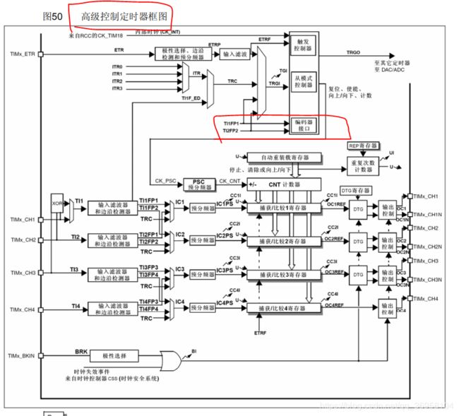
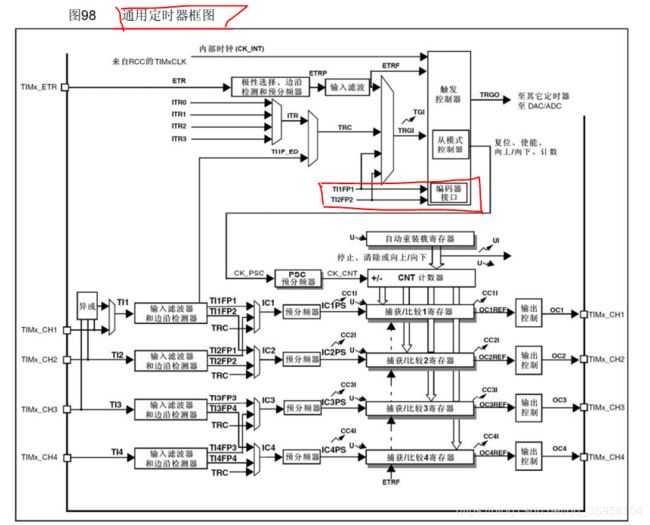
定时器时钟图
由此可看 无论是通用定时器还是高级定时器都可以 使用正交编码模式 只是 需要注意的是使用 定时器的通道1和通道2
本实验采用的增量式编码器
配置为下拉输入 PA0 PA1要加上拉电阻
#include "encoder.h"

/*************************定时器TIM2初始化****************************/
void left_encoder_init(void)
{
	GPIO_InitTypeDef GPIO_InitStructure;	//定义一个GPIO结构体变量
	TIM_TimeBaseInitTypeDef  TIM_TimeBaseStructure;//定义一个定时器结构体变量
	TIM_ICInitTypeDef TIM_ICInitStructure;	//定义一个定时器编码器结构体变量

	RCC_APB2PeriphClockCmd(RCC_APB2Periph_GPIOA, ENABLE);//使能GPIOA时钟
	RCC_APB1PeriphClockCmd(RCC_APB1Periph_TIM2, ENABLE);//使能定时器2

	GPIO_InitStructure.GPIO_Pin = GPIO_Pin_0|GPIO_Pin_1;		//配置PA0->TIM2_CH1,PA1->TIM2_CH2
	GPIO_InitStructure.GPIO_Speed = GPIO_Speed_50MHz;		//设置50MHz时钟
	GPIO_InitStructure.GPIO_Mode = GPIO_Mode_IPD;		//设置为下拉输入模式
	GPIO_Init(GPIOA, &GPIO_InitStructure);

	TIM_TimeBaseStructure.TIM_Period = 360*4;	//计数器最大值	编码器的脉冲数
	TIM_TimeBaseStructure.TIM_Prescaler = 0;	//时钟不分频
	TIM_TimeBaseStructure.TIM_ClockDivision = 0;	// 使用的采样频率之间的分频比例
	TIM_TimeBaseStructure.TIM_CounterMode = TIM_CounterMode_Up;	//向上计数
	TIM_TimeBaseInit(TIM2, &TIM_TimeBaseStructure);	//初始化定时器2

	TIM_EncoderInterfaceConfig(TIM2, TIM_EncoderMode_TI12,TIM_ICPolarity_Falling, TIM_ICPolarity_Falling);
	TIM_ICStructInit(&TIM_ICInitStructure);
	TIM_ICInitStructure.TIM_ICFilter = 6;//滤波器值
	TIM_ICInit(TIM2, &TIM_ICInitStructure);

	TIM_SetCounter(TIM2, 0x7fff);

	//  TIM_ClearITPendingBit(TIM2, TIM_IT_Update);		//清除定时器2中断标志位
	TIM_ClearFlag(TIM2, TIM_FLAG_Update);

	//	TIM_ITConfig(TIM2, TIM_IT_Update, ENABLE);		//打开定时器2中断
	TIM_Cmd(TIM2, ENABLE);  //计数器使能,开始计数
}


/*************************定时器TIM3初始化****************************/
void right_encoder_init(void)
{
	GPIO_InitTypeDef GPIO_InitStructure;	//定义一个GPIO结构体变量
	TIM_TimeBaseInitTypeDef  TIM_TimeBaseStructure;//定义一个定时器结构体变量
	TIM_ICInitTypeDef TIM_ICInitStructure;	//定义一个定时器编码器结构体变量

	RCC_APB2PeriphClockCmd(RCC_APB2Periph_GPIOA, ENABLE);//使能GPIOA时钟
	RCC_APB1PeriphClockCmd(RCC_APB1Periph_TIM3, ENABLE);//使能定时器3

	GPIO_InitStructure.GPIO_Pin = GPIO_Pin_6|GPIO_Pin_7;		//配置PA6->TIM3_CH1,PA7->TIM3_CH2
	GPIO_InitStructure.GPIO_Speed = GPIO_Speed_50MHz;		//设置50MHz时钟
	GPIO_InitStructure.GPIO_Mode = GPIO_Mode_IPD;		//设置为下拉输入模式
	GPIO_Init(GPIOA, &GPIO_InitStructure);

	TIM_TimeBaseStructure.TIM_Period = 0xffff;	//计数器最大值
	TIM_TimeBaseStructure.TIM_Prescaler = 0;	//时钟不分频
	TIM_TimeBaseStructure.TIM_ClockDivision = 0;	// 使用的采样频率之间的分频比例
	TIM_TimeBaseStructure.TIM_CounterMode = TIM_CounterMode_Up;	//向上计数
	TIM_TimeBaseInit(TIM3, &TIM_TimeBaseStructure);	//初始化定时器2

	TIM_EncoderInterfaceConfig(TIM3, TIM_EncoderMode_TI12,TIM_ICPolarity_Falling, TIM_ICPolarity_Falling);
	TIM_ICStructInit(&TIM_ICInitStructure);
	TIM_ICInitStructure.TIM_ICFilter = 6;
	TIM_ICInit(TIM3, &TIM_ICInitStructure);

	TIM_SetCounter(TIM3, 0x7fff);

	//  TIM_ClearITPendingBit(TIM3, TIM_IT_Update);		//清除定时器2中断标志位
	TIM_ClearFlag(TIM3, TIM_FLAG_Update);

	//	TIM_ITConfig(TIM3, TIM_IT_Update, ENABLE);		//打开定时器3中断
	TIM_Cmd(TIM3, ENABLE);  //计数器使能,开始计数
}
void encoder_init(void)
{
	left_encoder_init();	//初始化定时器2
	right_encoder_init();	//初始化定时器3
}
void get_encoder_count(int *_leftEncoderCount,int *_RightEncoderCount)
{
	*_leftEncoderCount=TIM_GetCounter(TIM2)-0x7fff;
	*_RightEncoderCount=TIM_GetCounter(TIM3)-0x7fff;		//读取编码器寄存器计数值,并减去中间值,得到速度矢量
	TIM_SetCounter(TIM2, 0x7fff);
	TIM_SetCounter(TIM3, 0x7fff);						//重置编码器计数值
}
主函数 将获取的编码器的角度数据 送到数组中 通过串口发送和显示到oled上
#include "stm32f10x.h"
#include "delay.h"
#include "usart.h"
#include "led.h"
#include "stdio.h"
#include "string.h"
#include "moto.h"
#include "timer.h"
#include "sys.h"
#include "pwm.h"
#include "guangdiankey.h"
#include "exti.h"
#include "key.h"
#include "wdg.h"
#include "oled.h"
#include "encoder.h"

//电机测试
#if 0
void test()
{
//拉低使能端
	GPIO_ResetBits(	D1_EN,D1_GPIO_EN);
//顺时针旋转180
 motor(D1_STEP,D1_DIR,D1_GPIO_STEP,D1_GPIO_DIR,0,100);

}
#endif

int main(void)
 {
	 int leftEncoderCount=0,RightEncoderCount=0;
	#if 0
	int flag=0;
	int flag1=10;
 	u8 t=0;
	u16 jiaodu[8];
	u16 SPEED_COUNT;
	#endif
	NVIC_PriorityGroupConfig(NVIC_PriorityGroup_2);//设置中断优先级分组为组2:2位抢占优先级,2位响应优先级
	delay_init();	    	 //延时函数初始化
	LED_Init();LED0=0;;//led初始化
	moto_Init();//电机初始化
	KEY_Init();	 //回零点的开关检测
	OLED_Init();//屏幕显示
	USART1_Configuration(115200);	 //串口初始化为115200
	EXTIX_Init();//外部中断初始化
	TIM1_Int_Init(1099,7200); //5hz 的计数频率,计数到 999 为 100ms
	TIM8_Int_Init(999,7200);	 //定时器8初始化  定时LED闪烁
	 left_encoder_init();
#if 0
	TIM2_PWM_Init(399,109);    //电机脉冲频率1.11630k
	TIM3_PWM_Init(399,109);    //	电机脉冲频率
	TIM4_PWM_Init(399,109);    //	电机脉冲频率
	TIM5_PWM_Init(399,109);    //	电机脉冲频率
	TIM2_PWM_Init(599,99);    //电机脉冲频率1.11630k
	TIM3_PWM_Init(599,99);    //	电机脉冲频率
	TIM4_PWM_Init(599,99);    //	电机脉冲频率
	TIM5_PWM_Init(599,99);    //	电机脉冲频率
	kaijidouhua();//开机屏幕显示
	#endif
	IWDG_Init(4,625);    //4*2^4与分频数为64,重载值为625,溢出时间为1s
	    TIM2->CNT = 0;//每次遇到相对零(Z信号)就将计数归0
    TIM_Cmd(TIM2, ENABLE);
  while(1)
	{
//	get_encoder_count(&leftEncoderCount,&RightEncoderCount);
//	crc16_data1[0]=leftEncoderCount;
		bianmaqi();//显示编码器的数据


	//	crc16_data1[0]=TIM_GetCounter(TIM2);//-0x7fff;
crc16_data1[0]=TIM2->CNT/4;


/*******************看门狗复位******************************/
		IWDG_ReloadCounter();//喂狗
	 }
 }


