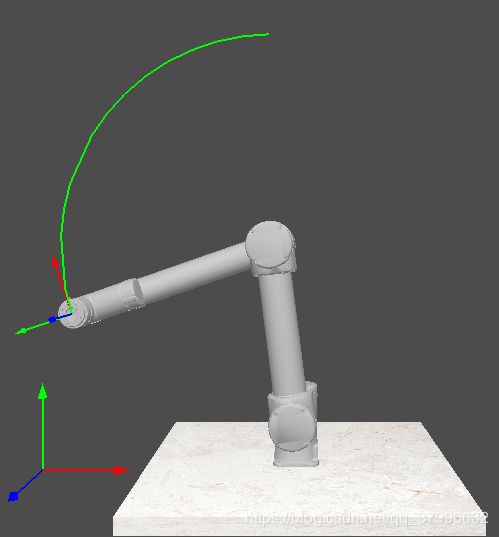
OpenGL中绘制轨迹线
在加载进模型后,有时候需要根据模型的移动来绘制轨迹线,假设该轨迹由机器人模型的某个关节,通过机器人关节的移动绘制出,思路如下:
- 获取机器人模型该关节在世界坐标系中的模型矩阵
- 根据模型矩阵及起点坐标的值,计算出模型移动时起点对应的空间坐标
- 去除重复坐标,存入数组中
- 通过glDrawArrays(GL_LINE_STRIP, 0, 数组size())绘制连续的轨迹线
代码实现:
定义绘制路径的VBO,类型为GLuint
GLuint pathVBO定义一个起点的坐标,假设为(0,0,0),类型为QVector3D
const QVector3D ORIGIN_POSITION(0.0f, 0.0f, 0.0f);定义关节的模型矩阵,类型为QMatrix4x4
QMatrix4x4 toolCoordScaling定义一个存储坐标的向量数组,类型为QVector
QVector pointVectices; 然后计算出经过关节的模型矩阵变换后的该起点位置,可用模型矩阵直接乘以类型为向量的坐标得到,在Qt中矩阵的类型为QMatrix4x4,三维向量的类型为QVector3D。注意相乘时矩阵在左向量在右,即用QMatrix4x4乘以QVector3D,在循环的paintGL()函数中把坐标向量追加到数组中。代码如下:
QVector3D vectice = toolCoordScaling * ORIGIN_POSITION;
if(pointVectices.size() == 0 || vectice != pointVectices.last())
{
    pointVectices.append(vectice);
}
创建绘制路径的着色器程序,分别是path.vert和path.frag两个文件,由于路径只是一条线,用最简单的着色器上个色就可以了,不用设置光照等。
path.vert
#version 330 core

layout (location = 0) in vec3 aPos;

uniform mat4 model;
uniform mat4 view;
uniform mat4 projection;

void main(){
    gl_Position = projection * view * model * vec4(aPos, 1.0f);
}
path.frag
#version 330 core

out vec4 FragColor;

void main()
{
    FragColor = vec4(0.0f, 1.0f, 0.0f, 1.0f);
}
接着写绘制的函数,此处不需要特意使用VAO,EBO等去绘制,由于各坐标都不相同,直接用VBO即可:
glBindBuffer(GL_ARRAY_BUFFER, pathVBO);
glBufferData(GL_ARRAY_BUFFER, pointVectices.size() * sizeof(QVector3D), &pointVectices[0], GL_STATIC_DRAW);
glVertexAttribPointer(0, 3, GL_FLOAT, GL_FALSE, 0, (void*)0);
glEnableVertexAttribArray(0);
ResourceManager::getShader("path").use().setMatrix4f("model", model);
glDrawArrays(GL_LINE_STRIP, 0, pointVectices.size());

ResourceManager::getShader("path").use().setMatrix4f("projection", projection);
ResourceManager::getShader("path").use().setMatrix4f("view", view);
效果如下:
