使用STM32和AD5420输出4-20mA的电路和程序
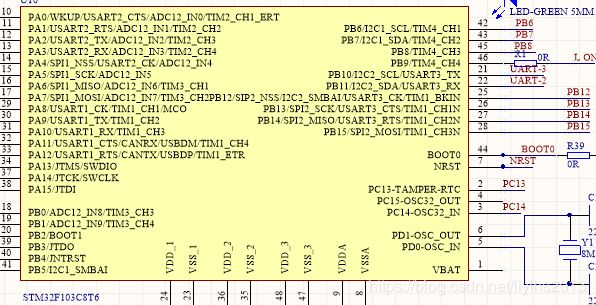
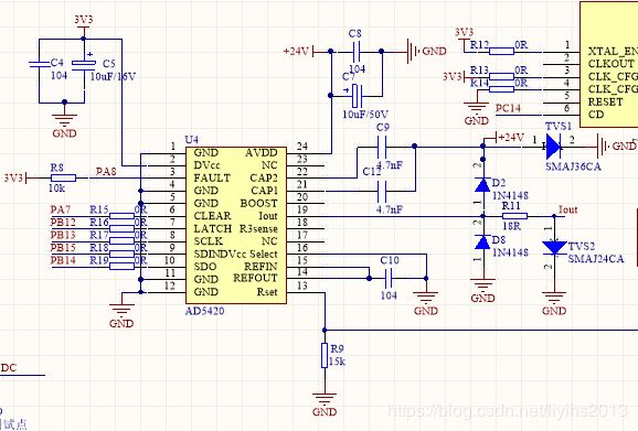
最近在做一个4-20mA输出的项目,遇到一些问题,但是还好顺利解决,使用STM32F103C8T6和AD5420,下面是电路图:
AD5420电路参考datasheet和CN0270,www.analog.com/CN0270.
通讯使用的是官方示例程序移植,官方为4-20mA,我这项目为了有其他模式所以改为0-24mA输出。
程序如下:
头文件如下:
#ifndef __AD5420_IO_H
#define __AD5420_IO_H

//#include "include.h"
//#include "sys.h"
/*----------------------------------------------------------------------
  File Name          : AD5420_IO.h
  Author             : Neil Zhao - CAST
  Version            : V1.0
  Date               : 1/8/2009
  Description        : AD5420 Driver Declaration

  The AD5410/AD5420 are low-cost, precision, fully integrated
  12/16-bit converter offering a programmable current source
  output designed to meet the requirements of industrial process
  control applications.

  China Applications Support Team.
  [email protected]

----------------------------------------------------------------------

  The present firmware which is for guidance only aims at providing
  customers with coding information regarding their products in order
  for them to save time.  As a result, Analog Devices shall not be
  held liable for any direct, indirect or consequential damages with
  respect to any claims arising from the content of such firmware and/or
  the use made by customers of the coding information contained herein
  in connection with their products.

----------------------------------------------------------------------*/
#define SET_CLEAR()		GPIO_SetBits(GPIOA,GPIO_Pin_7)	//PA7->CLEAR
#define CLR_CLEAR()		GPIO_ResetBits(GPIOA,GPIO_Pin_7)

#define SET_LATCH()		GPIO_SetBits(GPIOB,GPIO_Pin_12)	//PB12->LATCH
#define CLR_LATCH()		GPIO_ResetBits(GPIOB,GPIO_Pin_12)

#define	SET_SCL()		GPIO_SetBits(GPIOB,GPIO_Pin_13)	//PB13->SCLK
#define	CLR_SCL()		GPIO_ResetBits(GPIOB,GPIO_Pin_13)

#define SET_SDO()		GPIO_SetBits(GPIOB,GPIO_Pin_15)	//PB15->SDIN
#define CLR_SDO()		GPIO_ResetBits(GPIOB,GPIO_Pin_15)

//Function that writes to the AD5420 via the SPI port.
//--------------------------------------------------------------------------------
void WriteToAD5420(unsigned char count,unsigned char *Buf);

//Function that reads from the AD7190 via the SPI port.
//--------------------------------------------------------------------------------
void ReadFromAD5420(unsigned char count,unsigned char *buf);

void AD5420_IO_Init();//IO初始化

void delay (int length);
#endif


C文件如下:

/***************************************************************************

 Author        : Neil Zhao - CAST

 Date          : Feb 23th, 2009

 File          : ad5420driver_IO.c

 Hardware      : ADuC7026 and AD5420

 Description   : Use the GPIO to simulate the SPI communication of AD5420

***************************************************************************/

#include "AD5420_IO.h"
#include "stm32f10x.h"
//#include "sys.h"

void delay (int length)
{
	while (length >0)
    	length--;
}

//---------------------------------
//void WriteToAD5420(unsigned char count,unsigned char *Buf);
//---------------------------------
//Function that writes to the AD5420 via the SPI port.
//--------------------------------------------------------------------------------
void WriteToAD5420(unsigned char count,unsigned char *Buf)
{

	unsigned	char	ValueToWrite = 0;
  unsigned	char	i = 0;
	unsigned	char	j = 0;


	CLR_LATCH();

	for ( i=count;i>0;i-- )
 	{
	 	ValueToWrite =	*(Buf+i-1);
		for (j=0; j<8; j++)
		{
			CLR_SCL();
			if(0x80 == (ValueToWrite & 0x80))
			{
				SET_SDO();	    //Send one to SDIN pin of AD5420
			}
			else
			{
				CLR_SDO();	    //Send zero to SDIN pin of AD5420
			}

			delay(1);
			SET_SCL();
			delay(1);
			ValueToWrite <<= 1;	//Rotate data

		}

	}
	CLR_SCL();
	delay(1);
	SET_LATCH();
	delay(20);
}


//---------------------------------
//ReadFromAD5420();
//---------------------------------
//Function that reads from the AD5420 via the SPI port.
//--------------------------------------------------------------------------------
void ReadFromAD5420(unsigned char count,unsigned char *buf)
{
	unsigned	char	i = 0;
	unsigned	char	j = 0;
	unsigned	int  	iTemp = 0;
	unsigned	char  RotateData = 0;

	CLR_LATCH();

	for(j=count; j>0; j--)
	{
		for(i=0; i<8; i++)
		{
		  CLR_SCL();
			RotateData <<= 1;		//Rotate data
			delay(1);
			CLR_SDO();				//write a nop condition when read the data.
			iTemp = GPIO_ReadInputDataBit(GPIOB,GPIO_Pin_14);			//Read SDO of AD5420
			SET_SCL();
			if(0x00000020 == (iTemp & 0x00000020))
			{
				RotateData |= 1;
			}
			delay(1);

		}
		*(buf+j-1)= RotateData;
	}
	CLR_SCL();
	delay(1);
	SET_LATCH();
	delay(20);
}


////IO初始化
void AD5420_IO_Init()
{
	GPIO_InitTypeDef GPIO_InitStructure;
	/*根据GPIO_InitStructure中指定的参数初始化外设GPIOx寄存器*/
	//	RCC_APB2PeriphClockCmd(RCC_APB2Periph_GPIOB, ENABLE);
	RCC_APB2PeriphClockCmd(RCC_APB2Periph_GPIOA,ENABLE);
	RCC_APB2PeriphClockCmd(RCC_APB2Periph_GPIOB,ENABLE);

	////input:PA7->CLEAR; PB12->LATCH; PB13->SCLK; PB15->SDIN; output:PB14->SDIO; PA8->FAULT
	/*Configure SPI*/
	GPIO_InitStructure.GPIO_Pin = GPIO_Pin_7;
	GPIO_InitStructure.GPIO_Mode = GPIO_Mode_Out_PP;//输出
	GPIO_InitStructure.GPIO_Speed = GPIO_Speed_50MHz;
	GPIO_Init(GPIOA, &GPIO_InitStructure);

	GPIO_InitStructure.GPIO_Pin = GPIO_Pin_12|GPIO_Pin_13|GPIO_Pin_15;
	GPIO_InitStructure.GPIO_Mode = GPIO_Mode_Out_PP;//输出
	GPIO_InitStructure.GPIO_Speed = GPIO_Speed_50MHz;
	GPIO_Init(GPIOB, &GPIO_InitStructure);

	GPIO_InitStructure.GPIO_Pin = GPIO_Pin_8;	 //PA8 输入
	GPIO_InitStructure.GPIO_Mode = GPIO_Mode_IPD; //上拉输入
	GPIO_InitStructure.GPIO_Speed = GPIO_Speed_50MHz;
	GPIO_Init(GPIOA, &GPIO_InitStructure);

	GPIO_InitStructure.GPIO_Pin = GPIO_Pin_14;	 //PB14 输入
	GPIO_InitStructure.GPIO_Mode = GPIO_Mode_IPD; //上拉输入
	GPIO_InitStructure.GPIO_Speed = GPIO_Speed_50MHz;
	GPIO_Init(GPIOB, &GPIO_InitStructure);


	GPIO_ResetBits(GPIOB,GPIO_Pin_12|GPIO_Pin_13|GPIO_Pin_15);
	GPIO_ResetBits(GPIOA,GPIO_Pin_7);
}

主程序部分如下:
AD5420_IO_Init();

				buf[2] = 0x56;//复位寄存器
				buf[1] = 0x00;              //Disable Slew Rate
				buf[0] = 0x01;//复位
				WriteToAD5420(3,buf);	//Write 551005 to SHIFT REGISTER  to write 1005 to control register
				delay(2000);
				buf[2] = 0x55;//控制寄存器
				buf[1] = 0x30;//REXT=1,外部电流设置电阻;OUTEN=1,输出使能;禁能数字压摆率控制;菊花链禁能;0-24mA输出,这里为了有其他模式,可选4-20mA输出,请参考datasheet
				buf[0] = 0x07;
				WriteToAD5420(3,buf);
				delay(2000);

				ReadFromAD5420(3,buf);		//Read CONTROL REGISTER

				buf[2] = 0x01;//数据寄存器
				buf[1] = 0x11;
				buf[0] = 0x11;
				WriteToAD5420(3,buf);	//Write 019966H to SHIFT REGISTER  to write 9966 to DATA REGISTER
				delay(2000);

					ReadFromAD5420(3,buf);		//Read STATUS REGISTER

				buf[2] = 0x01;//数据寄存器
				buf[1] = 0x00;
				buf[0] = 0x00;//0mA
				WriteToAD5420(3,buf);
				delay(2000);

				buf[2] = 0x01;//数据寄存器
				buf[1] = 0x15;
				buf[0] = 0x55;//2mA
				WriteToAD5420(3,buf);
				delay(2000);

				buf[2] = 0x01;//数据寄存器
				buf[1] = 0x2A;
				buf[0] = 0xAA;//4mA
				WriteToAD5420(3,buf);
				delay(2000);

				buf[2] = 0x01;//数据寄存器
				buf[1] = 0x6A;
				buf[0] = 0xAA;//10mA
				WriteToAD5420(3,buf);
				delay(2000);

				buf[2] = 0x01;//数据寄存器
				buf[1] = 0xD5;
				buf[0] = 0x55;//20mA
				WriteToAD5420(3,buf);
				delay(2000);

				buf[2] = 0x01;//数据寄存器
				buf[1] = 0xFF;
				buf[0] = 0xFF;//24mA
				WriteToAD5420(3,buf);
				delay(2000);
测试使用fluke 15B串联在IOUT和GND,10mA为9.98mA,24mA为23.93,误差为0.3%,datasheet标示为0.15%,还算可以,跟硬件和万用表有关。

