STM32F429 使用 TCS34725 颜色传感器的驱动程序
用到了 TCS34725 颜色传感器,网上百度一圈都没有发现驱动程序,自己照着 Arduino 的程序和数据手册写了下,记录一下 (~ ̄▽ ̄)~
第一步,先来看看数据手册,了解到 TCS34725 是 I²C 器件,那就好办了,根据以前写的 I²C 驱动改一改就好啦 b( ̄▽ ̄)d(具体代码贴在后边)。
Communication of the TCS3472 data is accomplished over a fast, up to 400 kHz, two-wire I²C serial bus. The industry standard I²C bus facilitates easy, direct connection to microcontrollers and embedded processors.
然后干嘛嘞?当然是找器件地址和寄存器地址啦,继续翻手册…(⊙_⊙;)…
找到 TCS34725 地址为 0x29 ,各个寄存器的地址如下:
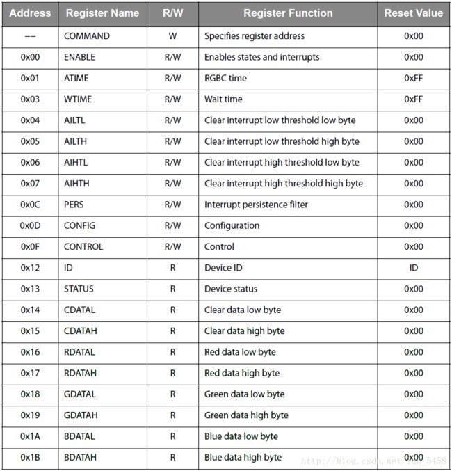
到这里,发现这货不仅器件地址是奇数,而且还有个没有地址的 COMMAND 寄存器,嗯,隐隐感觉肯定有个坑在这里 ヾ(。 ̄□ ̄)ツ゜゜゜
接下来就可以着手写程序啦 (o゜▽゜)o☆
首先定义一下用到的引脚:
/*********************************
*TCS34725相关宏定义
*********************************/
#define TCS_SDA_PIN_NUM       0
#define TCS_SDA_PIN           GPIO_PIN_0
#define TCS_SDA_GPIO          GPIOI
#define TCS_SCL_PIN           GPIO_PIN_1
#define TCS_SCL_GPIO          GPIOI
然后把之前写的 I²C 驱动程序粘过来改一下(^-^)V
//IO方向设置
#define TCS_SDA_DIR_IN()
{TCS_SDA_GPIO->MODER&=~(3<<(TCS_SDA_PIN_NUM*2));TCS_SDA_GPIO>MODER|=0<MODER&=~(3<<(TCS_SDA_PIN_NUM*2));TCS_SDA_GPIO>MODER|=1< 250)
		{
			TCS34725_I2C_Stop();
			return 1;
		}
	}
	TCS_SCL_RESET;//时钟输出0

	return 0;
}

//产生ACK应答
void TCS34725_I2C_ACK()
{
	TCS_SCL_RESET;
	TCS_SDA_DIR_OUT();//sda线输出
	TCS_SDA_RESET;
	delay_us(2);
	TCS_SCL_SET;
	delay_us(2);
	TCS_SCL_RESET;
}

//不产生ACK应答
void TCS34725_I2C_NACK()
{
	TCS_SCL_RESET;
	TCS_SDA_DIR_OUT();//sda线输出
	TCS_SDA_SET;
	delay_us(2);
	TCS_SCL_SET;
	delay_us(2);
	TCS_SCL_RESET;
}

//I2C发送一个字节
void TCS34725_I2C_Send_Byte(uint8_t byte)
{
	uint8_t i = 0;

	TCS_SDA_DIR_OUT();//sda线输出
	TCS_SCL_RESET;//拉低时钟开始数据传输
	for(i = 0; i < 8; i++)
	{
		((byte & 0x80) >> 7) == 0x01 ? TCS_SDA_SET : TCS_SDA_RESET;
		byte <<= 1;
		delay_us(2);
		TCS_SCL_SET;
		delay_us(2);
		TCS_SCL_RESET;
		delay_us(2);
	}
}

//读1个字节,ack=1时,发送ACK,ack=0,发送nACK
uint8_t TCS34725_I2C_Read_Byte(uint8_t ack)
{
	uint8_t i,receive = 0;

	TCS_SDA_DIR_IN();
	for(i = 0; i < 8; i++)
	{
		TCS_SCL_RESET;
		delay_us(2);
		TCS_SCL_SET;
		receive <<= 1;
		if(TCS_SDA_READ) receive++;
		delay_us(1);
	}
	if (!ack) TCS34725_I2C_NACK();//发送nACK
	else TCS34725_I2C_ACK(); //发送ACK

	return receive;
}
OK,以上就是最基本 I²C 的驱动程序,下边就到了第一个重点啦(~ ̄▽ ̄)~,也就是为毛这货的器件地址是个奇数,我们知道 I²C 的从机地址是 8 bit ,前 7 bit 是器件地址,最后 1 bit 代表是读操作(1)还是写操作(0),所以一般来说器件地址应该是偶数。但是,有的厂家给的地址是低 7 bit (例如这货),所以就会出现奇数的情况,这样就需要给它左移 1 bit 。
好了,地址的问题解决了,就可以写读操作和写操作的程序了
/***************************************************************************//**
 * @brief Writes data to a slave device.
 *
 * @param slaveAddress - Adress of the slave device.
 * @param dataBuffer - Pointer to a buffer storing the transmission data.
 * @param bytesNumber - Number of bytes to write.
 * @param stopBit - Stop condition control.
 *                  Example: 0 - A stop condition will not be sent;
 *                           1 - A stop condition will be sent.
*******************************************************************************/
void TCS34725_I2C_Write(uint8_t slaveAddress,
						uint8_t* dataBuffer,
						uint8_t bytesNumber,
						uint8_t stopBit)
{
	unsigned char i = 0;

	TCS34725_I2C_Start();
	TCS34725_I2C_Send_Byte((slaveAddress << 1) | 0x00);	   //发送从机地址写命令
	TCS34725_I2C_Wait_ACK();
	for(i = 0; i < bytesNumber; i++)
	{
		TCS34725_I2C_Send_Byte(*(dataBuffer + i));
		TCS34725_I2C_Wait_ACK();
	}
	if(stopBit == 1) TCS34725_I2C_Stop();
}

/***************************************************************************//**
 * @brief Reads data from a slave device.
 *
 * @param slaveAddress - Adress of the slave device.
 * @param dataBuffer - Pointer to a buffer that will store the received data.
 * @param bytesNumber - Number of bytes to read.
 * @param stopBit - Stop condition control.
 *                  Example: 0 - A stop condition will not be sent;
 *                           1 - A stop condition will be sent.
*******************************************************************************/
void TCS34725_I2C_Read(uint8_t slaveAddress,
						uint8_t* dataBuffer,
						uint8_t bytesNumber,
						uint8_t stopBit)
{
	unsigned char i = 0;

	TCS34725_I2C_Start();
	TCS34725_I2C_Send_Byte((slaveAddress << 1) | 0x01);	   //发送从机地址读命令
	TCS34725_I2C_Wait_ACK();
	for(i = 0; i < bytesNumber; i++)
	{
		if(i == bytesNumber - 1)
		{
			*(dataBuffer + i) = TCS34725_I2C_Read_Byte(0);//读取的最后一个字节发送NACK
		}
		else
		{
			*(dataBuffer + i) = TCS34725_I2C_Read_Byte(1);
		}
	}
	if(stopBit == 1) TCS34725_I2C_Stop();
}
基本驱动通讯搞定,接下来就给跟它唠唠嗑儿了,先定义一下暗号 (๑≧∀≦๑) ,暗号摘自 Arduino 下的驱动程序文件。
#define TCS34725_ADDRESS (0x29)
#define TCS34725_COMMAND_BIT (0x80)
#define TCS34725_ENABLE (0x00)
#define TCS34725_ENABLE_AIEN (0x10) /* RGBC Interrupt Enable */
#define TCS34725_ENABLE_WEN (0x08) /* Wait enable - Writing 1 activates the wait timer */
#define TCS34725_ENABLE_AEN (0x02) /* RGBC Enable - Writing 1 actives the ADC, 0 disables it */
#define TCS34725_ENABLE_PON (0x01) /* Power on - Writing 1 activates the internal oscillator, 0 disables it */
#define TCS34725_ATIME (0x01) /* Integration time */
#define TCS34725_WTIME (0x03) /* Wait time (if TCS34725_ENABLE_WEN is asserted) */
#define TCS34725_WTIME_2_4MS (0xFF) /* WLONG0 = 2.4ms WLONG1 = 0.029s */
#define TCS34725_WTIME_204MS (0xAB) /* WLONG0 = 204ms WLONG1 = 2.45s */
#define TCS34725_WTIME_614MS (0x00) /* WLONG0 = 614ms WLONG1 = 7.4s */
#define TCS34725_AILTL (0x04) /* Clear channel lower interrupt threshold */
#define TCS34725_AILTH (0x05)
#define TCS34725_AIHTL (0x06) /* Clear channel upper interrupt threshold */
#define TCS34725_AIHTH (0x07)
#define TCS34725_PERS (0x0C) /* Persistence register - basic SW filtering mechanism for interrupts */
#define TCS34725_PERS_NONE (0b0000) /* Every RGBC cycle generates an interrupt */
#define TCS34725_PERS_1_CYCLE (0b0001) /* 1 clean channel value outside threshold range generates an interrupt */
#define TCS34725_PERS_2_CYCLE (0b0010) /* 2 clean channel values outside threshold range generates an interrupt */
#define TCS34725_PERS_3_CYCLE (0b0011) /* 3 clean channel values outside threshold range generates an interrupt */
#define TCS34725_PERS_5_CYCLE (0b0100) /* 5 clean channel values outside threshold range generates an interrupt */
#define TCS34725_PERS_10_CYCLE (0b0101) /* 10 clean channel values outside threshold range generates an interrupt */
#define TCS34725_PERS_15_CYCLE (0b0110) /* 15 clean channel values outside threshold range generates an interrupt */
#define TCS34725_PERS_20_CYCLE (0b0111) /* 20 clean channel values outside threshold range generates an interrupt */
#define TCS34725_PERS_25_CYCLE (0b1000) /* 25 clean channel values outside threshold range generates an interrupt */
#define TCS34725_PERS_30_CYCLE (0b1001) /* 30 clean channel values outside threshold range generates an interrupt */
#define TCS34725_PERS_35_CYCLE (0b1010) /* 35 clean channel values outside threshold range generates an interrupt */
#define TCS34725_PERS_40_CYCLE (0b1011) /* 40 clean channel values outside threshold range generates an interrupt */
#define TCS34725_PERS_45_CYCLE (0b1100) /* 45 clean channel values outside threshold range generates an interrupt */
#define TCS34725_PERS_50_CYCLE (0b1101) /* 50 clean channel values outside threshold range generates an interrupt */
#define TCS34725_PERS_55_CYCLE (0b1110) /* 55 clean channel values outside threshold range generates an interrupt */
#define TCS34725_PERS_60_CYCLE (0b1111) /* 60 clean channel values outside threshold range generates an interrupt */
#define TCS34725_CONFIG (0x0D)
#define TCS34725_CONFIG_WLONG (0x02) /* Choose between short and long (12x) wait times via TCS34725_WTIME */
#define TCS34725_CONTROL (0x0F) /* Set the gain level for the sensor */
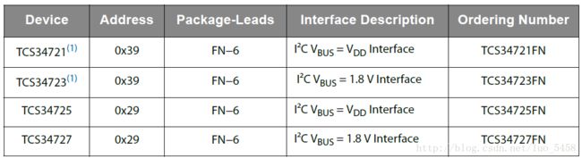
#define TCS34725_ID (0x12) /* 0x44 = TCS34721/TCS34725, 0x4D = TCS34723/TCS34727 */
#define TCS34725_STATUS (0x13)
#define TCS34725_STATUS_AINT (0x10) /* RGBC Clean channel interrupt */
#define TCS34725_STATUS_AVALID (0x01) /* Indicates that the RGBC channels have completed an integration cycle */
#define TCS34725_CDATAL (0x14) /* Clear channel data */
#define TCS34725_CDATAH (0x15)
#define TCS34725_RDATAL (0x16) /* Red channel data */
#define TCS34725_RDATAH (0x17)
#define TCS34725_GDATAL (0x18) /* Green channel data */
#define TCS34725_GDATAH (0x19)
#define TCS34725_BDATAL (0x1A) /* Blue channel data */
#define TCS34725_BDATAH (0x1B)
#define TCS34725_INTEGRATIONTIME_2_4MS 0xFF /**< 2.4ms - 1 cycle - Max Count: 1024 */
#define TCS34725_INTEGRATIONTIME_24MS 0xF6 /**< 24ms - 10 cycles - Max Count: 10240 */
#define TCS34725_INTEGRATIONTIME_50MS 0xEB /**< 50ms - 20 cycles - Max Count: 20480 */
#define TCS34725_INTEGRATIONTIME_101MS 0xD5 /**< 101ms - 42 cycles - Max Count: 43008 */
#define TCS34725_INTEGRATIONTIME_154MS 0xC0 /**< 154ms - 64 cycles - Max Count: 65535 */
#define TCS34725_INTEGRATIONTIME_240MS 0x9C /**< 240ms - 100 cycles - Max Count: 65535 */
#define TCS34725_INTEGRATIONTIME_700MS 0x00 /**< 700ms - 256 cycles - Max Count: 65535 */
#define TCS34725_GAIN_1X 0x00 /**< No gain */
#define TCS34725_GAIN_4X 0x01 /**< 4x gain */
#define TCS34725_GAIN_16X 0x02 /**< 16x gain */
#define TCS34725_GAIN_60X 0x03 /**< 60x gain */
发现其中有个 TCS34725_COMMAND_BIT ,而且发现 Arduino 代码中只要发送寄存器地址的地方都有它 (๑°ㅁ°๑)‼,此处必有蹊跷!翻开我们的葵花宝典,啊不,是数据手册,居然发现了这个!

宝典告诉我们,若要寻址,此 bit 必须置 1 ,也就是说我们在发送需要操作的寄存器地址时,必需要将 MSB 置为 1 。怪不得你丫儿没地址,原来哪都有你 (°ー°〃)
知道了这个就好办了,我们先封装一下基本的读写操作
/***************************************************************************//**
 * @brief Writes data into TCS34725 registers, starting from the selected
 *        register address pointer.
 *
 * @param subAddr - The selected register address pointer.
 * @param dataBuffer - Pointer to a buffer storing the transmission data.
 * @param bytesNumber - Number of bytes that will be sent.
 *
 * @return None.
*******************************************************************************/
void TCS34725_Write(unsigned char subAddr, unsigned char* dataBuffer, unsigned char bytesNumber)
{
    unsigned char sendBuffer[10] = {0, };
    unsigned char byte = 0;

    sendBuffer[0] = subAddr | TCS34725_COMMAND_BIT;
    for(byte = 1; byte <= bytesNumber; byte++)
    {
        sendBuffer[byte] = dataBuffer[byte - 1];
    }
	TCS34725_I2C_Write(TCS34725_ADDRESS, sendBuffer, bytesNumber + 1, 1);
}

/***************************************************************************//**
 * @brief Reads data from TCS34725 registers, starting from the selected
 *        register address pointer.
 *
 * @param subAddr - The selected register address pointer.
 * @param dataBuffer - Pointer to a buffer that will store the received data.
 * @param bytesNumber - Number of bytes that will be read.
 *
 * @return None.
*******************************************************************************/
void TCS34725_Read(unsigned char subAddr, unsigned char* dataBuffer, unsigned char bytesNumber)
{
	subAddr |= TCS34725_COMMAND_BIT;

	TCS34725_I2C_Write(TCS34725_ADDRESS, (unsigned char*)&subAddr, 1, 0);
	TCS34725_I2C_Read(TCS34725_ADDRESS, dataBuffer, bytesNumber, 1);
}
接下来就可以根据宝典里对各个寄存器的说明来编程了,我就写了我用到的几个功能 (๑・ิ-・ิ๑) ,各位看官有需要可以自己补充。废话不多说,上代码:
TCS34725 的 ID 是 0x44 可以根据这个来判断是否成功连接。
/***************************************************************************//**
 * @brief TCS34725初始化
 *
 * @return ID - ID寄存器中的值
*******************************************************************************/
unsigned char TCS34725_Init(void)
{
    unsigned char status[1] = {0};

	TCS34725_I2C_Init();
	TCS34725_Read(TCS34725_ID, status, 1);
    return status[0];
}
两个个主要设置,设置积分时间(ATIME 寄存器)和增益(CONTROL 寄存器)。这个直接和最后获取到的数据相关,积分时间越长,增益越大,最后获得值越大,需要根据实际应用情况进行设置。
积分时间的计算如下文所示:
The actual time can be calculated as follows:

ATIME = 256 − Integration Time / 2.4 ms

Inversely, the time can be calculated from the register value as follows:

Integration Time = 2.4 ms × (256 − ATIME)

For example, if a 100-ms integration time is needed, the device needs to be programmed to:

256 − (100 / 2.4) = 256 − 42 = 214 = 0xD6

Conversely, the programmed value of 0xC0 would correspond to:

(256 − 0xC0) × 2.4 = 64 × 2.4 = 154 ms.
/***************************************************************************//**
 * @brief TCS34725设置积分时间
 *
 * @return None
*******************************************************************************/
void TCS34725_SetIntegrationTime(uint8_t time)
{
	unsigned char cmd = time;

	TCS34725_Write(TCS34725_ATIME, &cmd, 1);
}
/***************************************************************************//**
 * @brief TCS34725设置增益
 *
 * @return None
*******************************************************************************/
void TCS34725_SetGain(uint8_t gain)
{
	unsigned char cmd = gain;

	TCS34725_Write(TCS34725_CONTROL, &cmd, 1);
}
/***************************************************************************//**
 * @brief TCS34725设置寄存器
 *
 * @return None
*******************************************************************************/
void TCS34725_Setup(void)
{
	TCS34725_SetIntegrationTime(TCS34725_INTEGRATIONTIME_240MS);
	TCS34725_SetGain(TCS34725_GAIN_4X);
}
器件上电后默认是在睡觉(Sleep 模式),得踹一脚(Enable)才醒(Idle 模式),然后告诉它是等一会干活还是马上滚去干活 (╯﹏╰)b
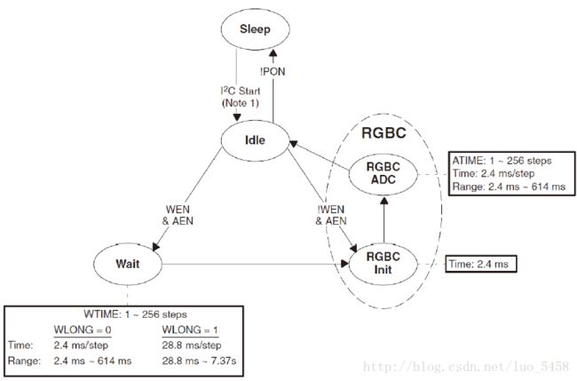
我这里让它直接干活去了,注意从 Idle 模式退出后,需要 2.4 ms 的时间来进行 RGBC 初始化,所以给个 3 ms 的延时就可以了。干完一次活后,如果不让它回去睡觉(Disable),就会自动继续干活,开始一个新的循环。(经@weixin_41605180提醒,原来这里写错了,应该是在设置AEN之后等待2.4 ms 的RGBC Init)
/***************************************************************************//**
 * @brief TCS34725使能
 *
 * @return None
*******************************************************************************/
void TCS34725_Enable(void)
{
	unsigned char cmd = TCS34725_ENABLE_PON;

	TCS34725_Write(TCS34725_ENABLE, &cmd, 1);
	//delay_ms(3);//延时应该放在设置AEN之后
	cmd = TCS34725_ENABLE_PON | TCS34725_ENABLE_AEN;
	TCS34725_Write(TCS34725_ENABLE, &cmd, 1);
	delay_ms(3);
}
/***************************************************************************//**
 * @brief TCS34725失能
 *
 * @return None
*******************************************************************************/
void TCS34725_Disable(void)
{
	unsigned char cmd = 0x00;

	TCS34725_Read(TCS34725_ENABLE, &cmd, 1);
	cmd = cmd & ~(TCS34725_ENABLE_PON | TCS34725_ENABLE_AEN);
	TCS34725_Write(TCS34725_ENABLE, &cmd, 1);
}
然后我们就可以拿到转换数据了,这里我根据自己的需要对 Arduino 的代码做了些修改
/***************************************************************************//**
 * @brief TCS34725获取单个通道数据
 *
 * @return data - 该通道的转换值
*******************************************************************************/
uint16_t TCS34725_GetChannelData(unsigned char reg)
{
	unsigned char tmp[2] = {0,0};
	uint16_t data = 0;

	TCS34725_Read(reg, tmp, 2);
	data = ((uint16_t)tmp[1] << 8) | tmp[0];

	return data;
}
/***************************************************************************//**
 * @brief TCS34725获取各个通道数据
 *
 * @return 1 - 转换完成,数据可用
 *   	   0 - 转换未完成,数据不可用
*******************************************************************************/
uint8_t TCS34725_GetRawData(uint16_t *r, uint16_t *g, uint16_t *b, uint16_t *c)
{
	unsigned char status[1] = {0};

	status[0] = TCS34725_STATUS_AVALID;

	TCS34725_Read(TCS34725_STATUS, status, 1);

	if(status[0] & TCS34725_STATUS_AVALID)
	{
		*c = TCS34725_GetChannelData(TCS34725_CDATAL);
		*r = TCS34725_GetChannelData(TCS34725_RDATAL);
		*g = TCS34725_GetChannelData(TCS34725_GDATAL);
		*b = TCS34725_GetChannelData(TCS34725_BDATAL);
		return 1;
	}
	return 0;
}
好了,到这里 TCS34725 的驱动程序就完成啦ヽ(=・ω・=)丿