在ROS中使用相机
在机器人中经常使用相机,在导航或者抓取规划时需要解析相机数据,需要理解相机图像的模式和相关的标签以及坐标系。本文介绍ROS中相机坐标的变换、相机标定、使用OpenCV进行简单的图像处理。
- 投影变换到相机坐标
- 相机内部校准标定
- 立体相机标定
- 在ROS中使用OpenCV
- 使用OpenCV寻找彩色像素点
- 查找边缘
投影变换到相机坐标
将图像与空间坐标相关联的投影变换的必要步骤是相机标定校准。这包括内部属性和外部属性。摄像机的固有属性保持不变,与摄像机的安装方式或其在空间中的移动方式无关。内部属性包括传感器尺寸(像素行和列的数量),图像平面的中心像素(取决于图像平面相对于理想化焦点的位置),焦点到图像平面的距离(焦距),透镜畸变模型的系数。外部属性有相机的安装方式。在校准外部属性前,相机的内部属性必须明确。
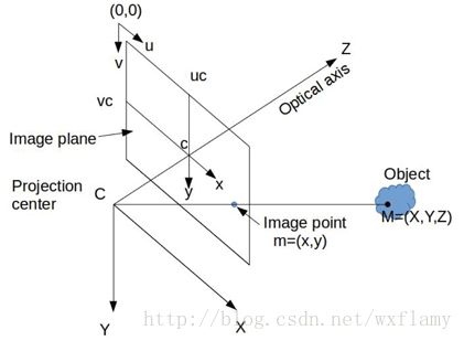
校准机器人需要定义相机坐标系,摄像机的标准坐标系如下图所示

设点C是针孔摄像机模型的焦点,也就是说针孔的位置在C处。这个点是投影中心(Projection center),将成为相机坐标系的中心。在焦点之后有一个感应平面,感应平面和观察对象之间的内容都会投射到感应平面上。感应平面有一个平面正交方向向量,我们将通过焦点C的正交光轴定义为z轴方向。感应平明按照像素分为行和列,我们定义x轴平行于行像素,y轴平行于列像素,组成右手直角坐标系(X,Y,Z)。
从环境到传感器平面的光线投射会产生倒像。通过数学变换在焦点前设置虚拟图像平面可以避免考虑倒像。这个图像平面与感应平面平行,但是与焦点有一定距离,这个距离被成为焦距(f)。图像平面有两个本地坐标系统:(x,y)和(u,v)。(u,v)坐标的原点在图形平面的角落,单位是像素。(x,y)坐标的原点在图像平面的中心,单位是米。常见的图像尺寸为 640×480 640 × 480 像素。他们之间的变换符合以下公式
其中 wpix w p i x 是一个像素的宽度, hpix h p i x 是一个像素的高度, uc u c 是图像像素宽度的一半,以此类推。
上图中有一个观察对象,相对于相机坐标系所在空间点为M(X,Y,Z),该点向焦点投射的光线与图像平面相交点在投影坐标系中为m(x,y),如果M点的坐标已知,那么m的坐标是可以计算出来的。图像平面与焦点的距离为焦距f,那么投影公式就是
上述计算用的参数都是相机固有的:焦距 f,像素中心 (uc,vc) ( u c , v c ) ,单位像素的宽 wpix w p i x 和高 hpix h p i x 。
除了线性相机模型之外,还可以考虑镜头失真。通常,这是通过如下找到用于径向和切向失真的解析近似的参数来完成的。给定M(X,Y,Z)我们可以计算m(x,y)。(x,y)可以利用焦距f归一化, (x′,y′)=(x/f,y/f) ( x ′ , y ′ ) = ( x / f , y / f ) 。在这些无量纲单位中,失真可以被建模为将 (x′,y′) ( x ′ , y ′ ) 线性投影映射到 (x″,y″) ( x ″ , y ″ ) 投影上受到畸变,并且随后可以将由此产生的光撞击预测转换为 (u,v) ( u , v ) 像素坐标。失真模型映射公式
越靠近图像中心 c点,失真参数越小,高阶失真就可以忽略了。失真模型通常包括二阶 k1,k2,p1,p2 k 1 , k 2 , p 1 , p 2 ,忽略高阶。发现失真模型参数也是相机内部标定的一部分。
相机内部校准标定
ROS通过camera_calibration包对相机校准标定进行支持,依赖OpenCV,相关理论和细节可以查看OpenCV的文档。校准程序假定使用具有已知数量的行和列以及已知尺寸的棋盘状视觉目标。 在进行校准过程中,校准可以像在相机前挥动校准目标一样简单。 该过程将获取目标的快照,通知用户何时有足够数量的用于识别的良好图像,然后根据所获取的图像计算内在参数。
这个过程可以在模拟中给出,给出相机的Gazebo仿真,视觉目标的模型以及将视觉目标移动到相机前方的方法。在simple_camera_model包中给出了相机标定的例子,Gazebo中相机的仿真仅指定一个静态机器人用作相机的支架。xacro文件如下
<robot name="simple_camera" xmlns:xacro="http://www.ros.org/wiki/xacro">

  <link name="world">
      <origin xyz="0.0 0.0 0.0"/>
  link>

  <joint name="camera_joint" type="fixed">
      <parent link="world"/>
      <child link="camera_link"/>
      <origin rpy="0.0 1.5708 1.5708" xyz="0 0.0 0.5"/>
  joint>

  <link name="camera_link">
    <visual>
      <origin xyz="0 0 0.0" rpy="0 0 0"/>
      <geometry>
        <box size="0.03 0.01 0.01"/>
      geometry>
    visual>

    <inertial>
      <mass value="1e-5" />
      <origin xyz="0 0 0" rpy="0 0 0"/>
      <inertia ixx="1e-6" ixy="0" ixz="0" iyy="1e-6" iyz="0" izz="1e-6" />
    inertial>
  link>


  <gazebo reference="camera_link">
    <sensor type="camera" name="camera">
      <update_rate>30.0update_rate>
      <camera name="camera">
        <horizontal_fov>0.6horizontal_fov>
        <image>
          <width>640width>
          <height>480height>
          <format>R8G8B8format>
        image>
        <clip>
          <near>0.005near>
          <far>0.9far>
        clip>
        <noise>
          <type>gaussiantype>
          <mean>0.0mean>
          <stddev>0.000stddev>
        noise>
      camera>
      <plugin name="camera_controller" filename="libgazebo_ros_camera.so">
        <alwaysOn>truealwaysOn>
        <updateRate>0.0updateRate>
        <cameraName>simple_cameracameraName>
        <imageTopicName>image_rawimageTopicName>
        <cameraInfoTopicName>camera_infocameraInfoTopicName>
        <frameName>camera_linkframeName>
        <distortionK1>0.0distortionK1>
        <distortionK2>0.0distortionK2>
        <distortionK3>0.0distortionK3>
        <distortionT1>0.0distortionT1>
        <distortionT2>0.0distortionT2>
      plugin>
    sensor>
  gazebo>

robot>
该模型文件在平面上方0.5米的位置建立了一个相机,相机的方向朝下。相机的像素参数为 640×480 640 × 480 ,每个像素通过8位编码,2的8次方,256。噪音和变形系数都可以自行设置,焦距通过视角0.6弧度间接指定。仿真图形将通过话题/simple_camera/image_raw发布图像消息。
启动这个文件的命令是
roslaunch simple_camera_model simple_camera_simu_w_checkerboard.launch启动文件包含多个步骤,开始启动gazebo、设置重力为0,加载加单摄像机模型,在gazebo中启动,寻找并加载模型。
使用
rostopic echo /simple_camera/camera_info 可以查看话题数据,
header:
  seq: 222
  stamp:
    secs: 1435
    nsecs: 383000000
  frame_id: "camera_link"
height: 480
width: 640
distortion_model: "plumb_bob"
D: [0.0, 0.0, 0.0, 0.0, 0.0]
K: [1034.4730060050647, 0.0, 320.5, 0.0, 1034.4730060050647, 240.5, 0.0, 0.0, 1.0]
R: [1.0, 0.0, 0.0, 0.0, 1.0, 0.0, 0.0, 0.0, 1.0]
P: [1034.4730060050647, 0.0, 320.5, -0.0, 0.0, 1034.4730060050647, 240.5, 0.0, 0.0, 0.0, 1.0, 0.0]
binning_x: 0
binning_y: 0
roi:
  x_offset: 0
  y_offset: 0
  height: 0
  width: 0
  do_rectify: False
这些数据包含传感器的参数,像素宽高(640*480),变形参数(distortion coefficient,D)为零,投影矩阵什么的,具体需要再查查。
标定板有七行八列的1cm的黑白相间的小方格,这些小方格构成了六行七列的内部四角交叉点,可以在校正过程中准确描述参考点的位置。
使用命令
rosrun image_view image_view image:=/simple_camera/image_raw可以在窗口中查看相机的图像信息。

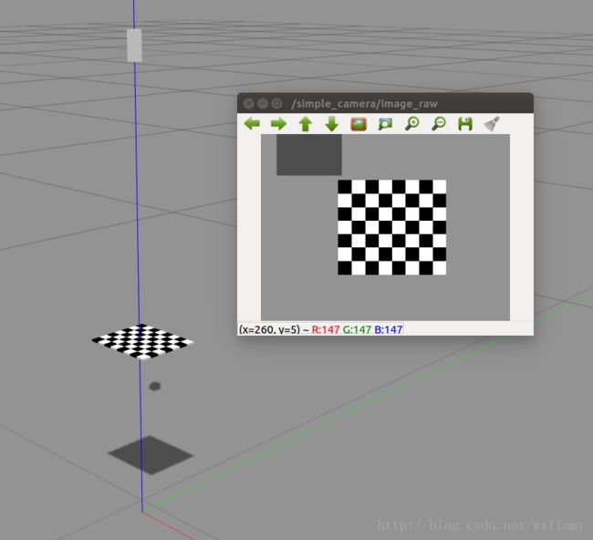
该图显示了代表相机机身的粗糙直角棱镜,光轴指向地平面。棋盘盘旋在地平面上方0.2米处,大约位于摄像机视野的中心。 Gazebo模拟中的光源将相机机身和棋盘的阴影投射到地平面上。 imageview中的显示显示相机看到棋盘,大约位于相机视野的中心位置。虚拟摄像机计算的合成图像中也可以看到棋盘投影的部分阴影。
为了模拟放置在摄像机(下方)前方的视觉目标(棋盘格),使用一个节点命令Gazebo移动该模型。移动棋盘使用部分中介绍的相同Gazebo界面。移动棋盘的代码位于example_camera_calibration包的src目录中,源文件名为move_calibration_checkerboard.cpp。此例程为棋盘生成随机姿态,约束于保持在相机视野内。棋盘垂直,水平移动,并以任意倾斜角度倾斜。棋盘格姿势每次持续0.5秒。使用以下命令可以不断改变标定板的位置
rosrun example_camera_calibration move_cabration_checkerboard使用以下命令可以对新位置进行采集标定
rosrun camera_calibration cameracalibrator.py --size 7x6 --square 0.01 image:=/simple_camera/image_raw camera:=/simple_camera直到Calibration按钮由灰变绿,可以停止变换位置,点击按钮,等待save 和Commit按钮变绿,依次点击,可以在目录~/.ros/camera_info中找到simple_camera.yaml文件,文件内容为标定结果
image_width: 640
image_height: 480
camera_name: simple_camera
camera_matrix:
  rows: 3
  cols: 3
  data:  [1033.456494901234, 0, 319.8868973720855,
          0, 1033.408215147896, 238.3374506780576,
          0, 0, 1]
distortion_model: plumb_bob
distortion_coefficients:
  rows: 1
  cols: 5
  data: [-0.0005442053507133286, -0.0187337496274687, -0.0003254625545871631, 0.0001351479074254773, 0]
rectification_matrix:
  rows: 3
  cols: 3
  data:  [1, 0, 0,
          0, 1, 0,
          0, 0, 1]
projection_matrix:
  rows: 3
  cols: 4
  data:  [1033.248657226562, 0, 319.927467515874, 0,
          0, 1033.325073242188, 238.2809272602481, 0,
          0, 0, 1, 0]
水平视角的正切值
中心坐标 (uc,vc)=(319.927467515874,238.2809272602481) ( u c , v c ) = ( 319.927467515874 , 238.2809272602481 ) 。
立体相机标定
立体相机依靠多个图像提供3d视觉。一般双目视觉。
在ROS中使用OpenCV
OpenCV是计算机视觉功能的开源函数库,由intel在1999年发布,在全世界范围内使用。ROS中提供了使用OpenCV的接口。
为了适应OpenCV类,ROS为了处理图像定制了发布和订阅功能。ROS中的图像转换结构包含类和节点。由于图像会占用很高的带宽,需要尽可能的限制网络负担。所以图像转换(imagetransport)的发布和订阅机制有些不同。首先,如果没有对图像转化话题的订阅者,那么话题上的消息将不会被发布,这样节省了带宽;其次,图像转换过程中的发布者和订阅者可以自动的压缩和解压图像,限制带宽消耗。这部分只是演示在ROS中使用OpenCV,并不能代替教程。
使用OpenCV寻找彩色像素点
在这个软件包中,image_transport用于利用为图像定制的高效发布和订阅功能。 cv_bridge库支持OpenCV数据类型和ROS消息之间的转换。 sensor_msgs包描述了ROS主题上发布的图像的格式。
可以在example_opencv文件夹中找到源码fide_red_pixels.cpp,在编译前要注意对CMakeLists.txt文件做些修改1:
#uncomment next line to use OpenCV library
find_package(OpenCV REQUIRED)
if(OpenCV_FOUND)
   message("Found OpenCV")
   message("Includes: " ${OpenCV_INCLUDE_DIRS})
endif(OpenCV_FOUND)
######################################

target_link_libraries(find_red_pixels ${OpenCV_LIBS})
target_link_libraries(find_features ${OpenCV_LIBS})
这样ROS就能够找到OpenCV了。
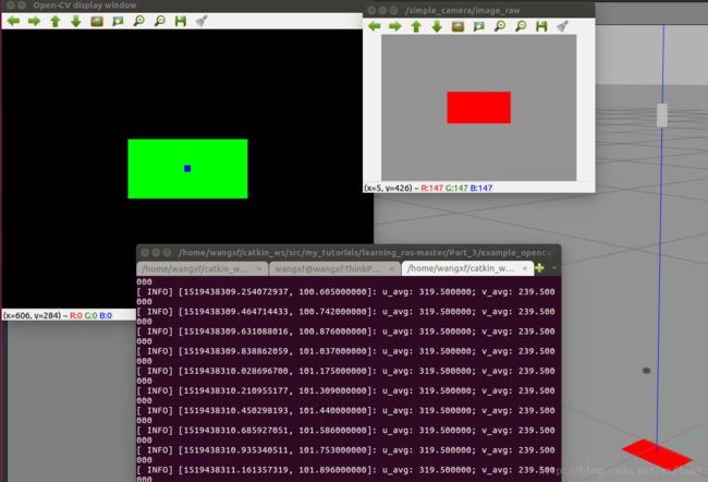
例子中的代码计算两个输出图像。其中一个图像是黑白的,除了所要找的红色像素位置,其他都是黑色,而红色像素位置设为白色;第二张图片是彩色图片的复制,但是叠加了一个在红色像素中心加入小蓝块的图片。
代码如下:
//get images from topic "simple_camera/image_raw"; remap, as desired;
//search for red pixels;
// convert (sufficiently) red pixels to white, all other pixels black
// compute centroid of red pixels and display as a blue square
// publish result of processed image on topic "/image_converter/output_video"
#include
#include (j, i); //extract an RGB pixel
//examine intensity of R, G and B components (0 to 255)
redval = rgbpix[2] + 1; //add 1, to avoid divide by zero
blueval = rgbpix[0] + 1;
greenval = rgbpix[1] + 1;
//look for red values that are large compared to blue+green
testval = redval / (blueval + greenval);
//if red (enough), paint this white:
if (testval > g_redratio) {
cv_ptr->image.at(j, i)[0] = 255;
cv_ptr->image.at(j, i)[1] = 255;
cv_ptr->image.at(j, i)[2] = 255;
npix++; //note that found another red pixel
isum += i; //accumulate row and col index vals
jsum += j;
} else { //else paint it black
cv_ptr->image.at(j, i)[0] = 0;
cv_ptr->image.at(j, i)[1] = 0;
cv_ptr->image.at(j, i)[2] = 0;
}
}
}
//cout << "npix: " << npix << endl;
//paint in a blue square at the centroid:
int half_box = 5; // choose size of box to paint
int i_centroid, j_centroid;
double x_centroid, y_centroid;
if (npix > 0) {
i_centroid = isum / npix; // average value of u component of red pixels
j_centroid = jsum / npix; // avg v component
x_centroid = ((double) isum)/((double) npix); //floating-pt version
y_centroid = ((double) jsum)/((double) npix);
ROS_INFO("u_avg: %f; v_avg: %f",x_centroid,y_centroid);
//cout << "i_avg: " << i_centroid << endl; //i,j centroid of red pixels
//cout << "j_avg: " << j_centroid << endl;
for (int i_box = i_centroid - half_box; i_box <= i_centroid + half_box; i_box++) {
for (int j_box = j_centroid - half_box; j_box <= j_centroid + half_box; j_box++) {
//make sure indices fit within the image
if ((i_box >= 0)&&(j_box >= 0)&&(i_box < cv_ptr->image.cols)&&(j_box < cv_ptr->image.rows)) {
cv_ptr->image.at(j_box, i_box)[0] = 255; //(255,0,0) is pure blue
cv_ptr->image.at(j_box, i_box)[1] = 0;
cv_ptr->image.at(j_box, i_box)[2] = 0;
}
}
}
}
// Update GUI Window; this will display processed images on the open-cv viewer.
cv::imshow(OPENCV_WINDOW, cv_ptr->image);
cv::waitKey(3); //need waitKey call to update OpenCV image window
// Also, publish the processed image as a ROS message on a ROS topic
// can view this stream in ROS with:
//rosrun image_view image_view image:=/image_converter/output_video
image_pub_.publish(cv_ptr->toImageMsg());
}
int main(int argc, char** argv) {
ros::init(argc, argv, "red_pixel_finder");
ros::NodeHandle n; //
ImageConverter ic(n); // instantiate object of class ImageConverter
//cout << "enter red ratio threshold: (e.g. 10) ";
//cin >> g_redratio;
g_redratio= 10; //choose a threshold to define what is "red" enough
ros::Duration timer(0.1);
double x, y, z;
while (ros::ok()) {
ros::spinOnce();
timer.sleep();
}
return 0;
} 使用以下命令可以启动演示文件
roslaunch simple_camera_model simple_camera_simu.launchroslaunch example_opencv find_red_pixels.launch使用以下命令可以单独查看发布的图像信息
rosrun image_view image_view image:=/image_converter/output_videosimple_camera_simu.launch的文件内容如下,启动了相机,加入了红色块。
<launch>


  <arg name="paused" default="false"/>
  <arg name="use_sim_time" default="true"/>
  <arg name="extra_gazebo_args" default=""/>
  <arg name="gui" default="true"/>
  <arg name="headless" default="false"/>
  <arg name="debug" default="false"/>
  <arg name="physics" default="ode"/>
  <arg name="verbose" default="false"/>
  <arg name="world_name" default="worlds/empty.world"/>


  <group if="$(arg use_sim_time)">
    <param name="/use_sim_time" value="true" />
  group>


  <arg unless="$(arg paused)" name="command_arg1" value=""/>
  <arg     if="$(arg paused)" name="command_arg1" value="-u"/>
  <arg unless="$(arg headless)" name="command_arg2" value=""/>
  <arg     if="$(arg headless)" name="command_arg2" value="-r"/>
  <arg unless="$(arg verbose)" name="command_arg3" value=""/>
  <arg     if="$(arg verbose)" name="command_arg3" value="--verbose"/>
  <arg unless="$(arg debug)" name="script_type" value="gzserver"/>
  <arg     if="$(arg debug)" name="script_type" value="debug"/>


  <node name="gazebo" pkg="gazebo_ros" type="$(arg script_type)" respawn="false" output="screen"
    args="$(arg command_arg1) $(arg command_arg2) $(arg command_arg3) -e $(arg physics) $(arg extra_gazebo_args) $(arg world_name)" />


  <group if="$(arg gui)">
    <node name="gazebo_gui" pkg="gazebo_ros" type="gzclient" respawn="false" output="screen"/>
  group>


  <param name="robot_description" command="$(find xacro)/xacro.py '$(find simple_camera_model)/simple_camera_model.xacro'" />


<node name="spawn_urdf" pkg="gazebo_ros" type="spawn_model" args="-param robot_description -urdf -model simple_camera" />

<node name="spawn_sdf" pkg="gazebo_ros" type="spawn_model" args="-file $(find exmpl_models)/colored_block/model-1_4.sdf -sdf -model block -z 0.01" />

launch>
find_red_pixels.launch文件如下
<launch>

    <node pkg="tf" type="static_transform_publisher" name="camera_frame_bdcst" args="0 0 0 -1.5708 0 -1.5708   camera_link camera_optical_frame 50"/>

    <node pkg="image_view" type="image_view" name="image_view">
        <remap from="image" to="simple_camera/image_raw"/>
    node>

    <node pkg="example_opencv" type="find_red_pixels" name="find_red_pixels" output="screen"/>

launch>
查找边缘
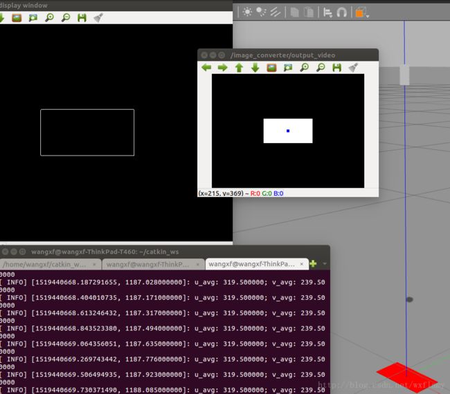
上面的例子是针对单个像素进行的。更常见的应用是使用高级函数。find_features.cpp中使用Canny滤波器查找图像的边缘。
find_features.cpp的内容:
//get images from topic "simple_camera/image_raw"; remap, as desired;
//search for red pixels;
// convert (sufficiently) red pixels to white, all other pixels black
// compute centroid of red pixels and display as a blue square
// publish result of processed image on topic "/image_converter/output_video"
#include (j, i); //extract an RGB pixel
//examine intensity of R, G and B components (0 to 255)
redval = rgbpix[2] + 1; //add 1, to avoid divide by zero
blueval = rgbpix[0] + 1;
greenval = rgbpix[1] + 1;
//look for red values that are large compared to blue+green
testval = redval / (blueval + greenval);
//if red (enough), paint this white:
if (testval > g_redratio) {
cv_ptr->image.at(j, i)[0] = 255;
cv_ptr->image.at(j, i)[1] = 255;
cv_ptr->image.at(j, i)[2] = 255;
npix++; //note that found another red pixel
isum += i; //accumulate row and col index vals
jsum += j;
} else { //else paint it black
cv_ptr->image.at(j, i)[0] = 0;
cv_ptr->image.at(j, i)[1] = 0;
cv_ptr->image.at(j, i)[2] = 0;
}
}
}
cv::Mat gray_image,contours;
//convert the color image to grayscale:
cv::cvtColor(cv_ptr->image, gray_image, CV_BGR2GRAY);
//use Canny filter to find edges in grayscale image;
//put result in "contours"; low and high thresh are tunable params
cv::Canny(gray_image,// gray-level image
contours, // output contours
125,// low threshold
350);// high threshold
//cout << "npix: " << npix << endl;
//paint in a blue square at the centroid:
int half_box = 5; // choose size of box to paint
int i_centroid, j_centroid;
double x_centroid, y_centroid;
if (npix > 0) {
i_centroid = isum / npix; // average value of u component of red pixels
j_centroid = jsum / npix; // avg v component
x_centroid = ((double) isum)/((double) npix); //floating-pt version
y_centroid = ((double) jsum)/((double) npix);
ROS_INFO("u_avg: %f; v_avg: %f",x_centroid,y_centroid);
//cout << "i_avg: " << i_centroid << endl; //i,j centroid of red pixels
//cout << "j_avg: " << j_centroid << endl;
for (int i_box = i_centroid - half_box; i_box <= i_centroid + half_box; i_box++) {
for (int j_box = j_centroid - half_box; j_box <= j_centroid + half_box; j_box++) {
//make sure indices fit within the image
if ((i_box >= 0)&&(j_box >= 0)&&(i_box < cv_ptr->image.cols)&&(j_box < cv_ptr->image.rows)) {
cv_ptr->image.at(j_box, i_box)[0] = 255; //(255,0,0) is pure blue
cv_ptr->image.at(j_box, i_box)[1] = 0;
cv_ptr->image.at(j_box, i_box)[2] = 0;
}
}
}
}
// Update GUI Window; this will display processed images on the open-cv viewer.
//cv::imshow(OPENCV_WINDOW, cv_ptr->image); //display processed image
cv::imshow(OPENCV_WINDOW, gray_image); //display the grayscale image
//cv::imshow(OPENCV_WINDOW, contours); //display the contours
cv::waitKey(3); //need waitKey call to update OpenCV image window
// Also, publish the processed image as a ROS message on a ROS topic
// can view this stream in ROS with:
//rosrun image_view image_view image:=/image_converter/output_video
image_pub_.publish(cv_ptr->toImageMsg());
}
}; //end of class definition
int main(int argc, char** argv) {
ros::init(argc, argv, "red_pixel_finder");
ros::NodeHandle n; //
ImageConverter ic(n); // instantiate object of class ImageConverter
//cout << "enter red ratio threshold: (e.g. 10) ";
//cin >> g_redratio;
g_redratio= 10; //choose a threshold to define what is "red" enough
ros::Duration timer(0.1);
double x, y, z;
while (ros::ok()) {
ros::spinOnce();
timer.sleep();
}
return 0;
} 先把图像转化成灰度图像,然后在灰度图像中利用滤波器找到边缘。
运行所需要的命令:
roslaunch simple_camera_model simple_camera_simu.launchrosrun example_opencv find_featuresrosrun image_view image_view image:=/age_converter/output_video![]()
- https://www.cnblogs.com/newneul/p/8364924.html ↩

