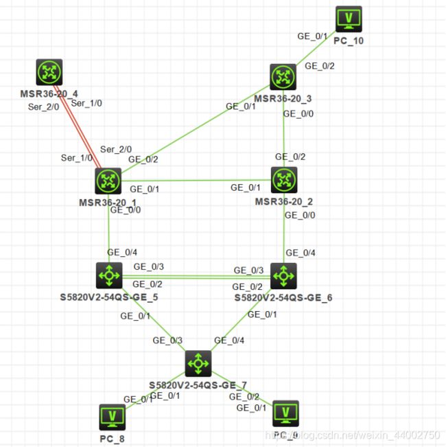
H3CNE综合实验
实验要求
1、按照图示配置 IP 地址
2、SW1 和 SW2 之间的直连链路配置链路聚合
3、公司内部业务网段为 Vlan10 和 Vlan20;Vlan10 是市场部,Vlan20 是技术部,要求对 Vlan 进行命名以便识别;PC1 属于 Vlan10,PC2 属于 Vlan20,Vlan30 用于 SW1 和 SW2 建立 OSPF 邻居;Vlan111 为 SW1 和 R1 的互联 Vlan,Vlan222 为 SW2 和 R2 的互联 Vlan
4、所有交换机相连的端口配置为 Trunk,允许相关流量通过
5、交换机连接 PC 的端口配置为边缘端口
6、在 SW1 上配置 DHCP 服务,为 Vlan10 和 Vlan20 的 PC 动态分配 IP 地址、网关和 DNS 地址;要求 Vlan10 的网关是 192.168.1.252,Vlan20 的网关是 192.168.2.253
7、按图示分区域配置 OSPF 实现公司内部网络全网互通,ABR 的环回口宣告进骨干区域;业务网段不允许出现协议报文
8、R1 上配置默认路由指向互联网,并引入到 OSPF
9、R1 通过双线连接到互联网,配置 PPP-MP,并配置双向 chap 验证
10、配置 EASY IP,只有业务网段 192.168.1.0/24 和 192.168.2.0/24 的数据流可以通过 R1 访问互联网
11、R1 开启 TELNET 远程管理,使用用户 abc 登录,密码 abc,只允许技术部远程管理 R1
实验拓扑
(1)各个主机的ip配置(环回口的ip是32位掩码,业务网段的ip是24位掩码,其余的交换机,路由器之间的ip是30位掩码)
[R1]dis ip int b
*down: administratively down
(s): spoofing  (l): loopback
Interface                Physical Protocol IP Address      Description
GE0/0                    up       up       10.0.0.5        --
GE0/1                    up       up       10.0.0.1        --
GE0/2                    up       up       10.0.0.14       --
Loop0                    up       up(s)    1.1.1.1         --
MP1                      up       up       202.100.1.2     --

[R2]dis ip int b
*down: administratively down
(s): spoofing  (l): loopback
Interface                Physical Protocol IP Address      Description
GE0/0                    up       up       10.0.0.9        --
GE0/1                    up       up       10.0.0.2        --
GE0/2                    up       up       10.0.0.18       --
Loop0                    up       up(s)    2.2.2.2         --

[R3]dis ip int b
*down: administratively down
(s): spoofing  (l): loopback
Interface                Physical Protocol IP Address      Description
GE0/0                    up       up       10.0.0.17       --
GE0/1                    up       up       10.0.0.13       --
GE0/2                    up       up       192.168.3.254   --
Loop0                    up       up(s)    3.3.3.3         -


[INTENET]dis ip int b
*down: administratively down
(s): spoofing  (l): loopback
Interface                Physical Protocol IP Address      Description
Loop0                    up       up(s)    100.1.1.1       --
MP1                      up       up       202.100.1.1     --

[SW1]dis ip int b
*down: administratively down
(s): spoofing  (l): loopback
Interface                Physical Protocol IP Address      Description
Loop0                    up       up(s)    11.11.11.11     --
Vlan10                   up       up       192.168.1.252   --
Vlan20                   up       up       192.168.2.252   --
Vlan30                   up       up       10.1.2.1        --
Vlan100                  up       up       10.0.0.6        --

[SW2]dis ip int b
*down: administratively down
(s): spoofing  (l): loopback
Interface                Physical Protocol IP Address      Description
Loop0                    up       up(s)    12.12.12.12     --
MGE0/0/0                 down     down     --              --
Vlan10                   up       up       192.168.1.253   --
Vlan20                   up       up       192.168.2.253   --
Vlan30                   up       up       10.1.2.2        --
Vlan200                  up       up       10.0.0.10       --
(2)配置DHCP
[SW1]dhcp enable
[SW1]dhcp server ip-pool 1  //创建地址池
[SW1-dhcp-pool-1]network 192.168.1.0 mask 255.255.255.0//地址池的ip范围
[SW1-dhcp-pool-1]gateway-list 192.168.1.252  //网关地址
[SW1-dhcp-pool-1]dns-list 114.114.114.114   //服务器地址

[SW1]dhcp enable
[SW1]dhcp server ip-pool 2  //创建地址池
[SW1-dhcp-pool-1]network 192.168.2.0 mask 255.255.255.0//地址池的ip范围
[SW1-dhcp-pool-1]gateway-list 192.168.2.253  //网关地址
[SW1-dhcp-pool-1]dns-list 114.114.114.114   //服务器地址

//SW3做中继
[SW3]int vlan 10
[SW3-Vlan-interface10]hdcp select relay
[SW3]int vlan 20
[SW3-Vlan-interface20]hdcp select relay
(3)在SW3上划分VLAN分别把g1/0/1、g1/0/2划分到VLAN 10,VLAN 20下
其中还要高VLAN10,VLAN30进行命名方便标识,把g1/0/1、g1/0/2设置为边缘端口
[SW3]vlan 10
[SW3-vlan10]port g1/0/1
[SW3-vlan10]vlan 20
[SW3-vlan20]port g1/0/2
[SW3-vlan20]name jsb
[SW3-vlan20]vlan 10
[SW3-vlan10]name scb
[SW3-vlan10]int g1/0/3
[SW3-GigabitEthernet1/0/3]port link-type tr
[SW3-GigabitEthernet1/0/3]port tr per vlan 10 20
[SW3-GigabitEthernet1/0/3]int g1/0/4
[SW3-GigabitEthernet1/0/4]port link-type tr
[SW3-GigabitEthernet1/0/4]port tr per vlan 10 20

[SW3-GigabitEthernet1/0/2]stp edged-port
[SW3-GigabitEthernet1/0/1]stp edged-port
(4)SW1和SW2进行链路聚合
[SW1]int Bridge-Aggregation 1
[SW1]int g1/0/2
[SW1-GigabitEthernet1/0/2]port link-aggregation group 1
[SW1-GigabitEthernet1/0/2]int g1/0/3
[SW1-GigabitEthernet1/0/3]port link-aggregation group 1

[SW1]interface Bridge-Aggregation 1
[SW1-Bridge-Aggregation1] port trunk permit vlan 1 10 20 30

[SW2]int Bridge-Aggregation 1
[SW2]int g1/0/2
[SW2-GigabitEthernet1/0/2]port link-aggregation group 1
[SW2-GigabitEthernet1/0/2]int g1/0/3
[SW2-GigabitEthernet1/0/3]port link-aggregation group 1

[SW2]interface Bridge-Aggregation 1
[SW2-Bridge-Aggregation1] port trunk permit vlan 1 10 20 30
(5)配置ospf是内网互通
注意:在配置与路由器建立邻居的VLAN时一定要在VLAN上加入端口
[R1]ospf
[R1-ospf-1]dis th
#
ospf 1 router-id 1.1.1.1
 default-route-advertise
 import-route static
 area 0.0.0.0
  network 1.1.1.1 0.0.0.0
  network 10.0.0.1 0.0.0.0
  network 10.0.0.14 0.0.0.0
 area 0.0.0.1
  network 10.0.0.5 0.0.0.0
#
Return

[R2-ospf-1]dis th
#
ospf 1 router-id 2.2.2.2
 import-route static
 area 0.0.0.0
  network 2.2.2.2 0.0.0.0
  network 10.0.0.2 0.0.0.0
  network 10.0.0.18 0.0.0.0
 area 0.0.0.1
  network 10.0.0.9 0.0.0.0
#
Return

[R3-ospf-1]dis th
#
ospf 1 router-id 3.3.3.3
 silent-interface GigabitEthernet0/2 //静默业务网段
 area 0.0.0.0
  network 3.3.3.3 0.0.0.0
  network 10.0.0.13 0.0.0.0
  network 10.0.0.17 0.0.0.0
  network 192.168.3.254 0.0.0.0
#
return
[SW1-ospf-1]dis th
#
ospf 1 router-id 11.11.11.11
 silent-interface Vlan-interface10  //静默业务网段
 silent-interface Vlan-interface20
 area 0.0.0.1
  network 10.0.0.6 0.0.0.0
  network 10.1.2.1 0.0.0.0
  network 11.11.11.11 0.0.0.0
  network 192.168.1.0 0.0.0.255
  network 192.168.2.0 0.0.0.255
#
return

[SW2-ospf-1]dis th
#
ospf 1 router-id 12.12.12.12
 silent-interface Vlan-interface10
 silent-interface Vlan-interface20
 area 0.0.0.1
  network 10.0.0.10 0.0.0.0
  network 10.1.2.2 0.0.0.0
  network 12.12.12.12 0.0.0.0
  network 192.168.1.0 0.0.0.255
  network 192.168.2.0 0.0.0.255
#
return
[SW2-ospf-1]

//在R1上配置静态路由,实现内网与外网的互通

[R1]dis ip routing-table

Destinations : 37       Routes : 38

Destination/Mask   Proto   Pre Cost        NextHop         Interface
0.0.0.0/0          Static  60  0           202.100.1.1     MP1
//在R1上引入缺省路由以便其他路由器可以学习默认路由
[R1-ospf-1]dis th
#
 default-route-advertise
#
(6)在R1 通过双线连接到互联网,配置 PPP-MP,并配置双向 chap 验证
注意:验证一定要配置在物理口上
[R1]int MP-group 1  //创建mp组
[R1-MP-group1]int s1/0  //进入到接口加入组
[R1-Serial1/0]ppp mp MP-group 1
[R1-Serial1/0]int s2/0
[R1-Serial2/0]ppp mp mp 1
[R1-MP-group1]ip add 202.100.1.2 30

[INTENET]int MP-group 1  //创建mp组
[INTENET-MP-group1]int s1/0  //进入到接口加入组
[INTENET-Serial1/0]ppp mp MP-group 1
[INTENET-Serial1/0]int s2/0
[INTENET-Serial2/0]ppp mp mp 1
[INTENET-MP-group1]ip add 202.100.1.1 30
[R1-Serial1/0]dis th
#
interface Serial1/0
 ppp authentication-mode chap
 ppp chap user xiao
 ppp mp MP-group1
#
[R1-Serial2/0]dis th
#
interface Serial2/0
 ppp authentication-mode chap
 ppp chap user xiao
 ppp mp MP-group1
#
[R1]local-user xiao class network
New local user added.
[R1-luser-network-xiao]pa
[R1-luser-network-xiao]password sim
[R1-luser-network-xiao]password simple 123
[R1-luser-network-xiao]ser
[R1-luser-network-xiao]service-type ppp

[INTENET-Serial1/0]dis th  //在接口上配置验证
#
interface Serial1/0
 ppp authentication-mode chap
 ppp chap user xiao
 ppp mp MP-group1
#
[INTENET-Serial2/0]dis th  //在接口上配置验证
#
interface Serial1/0
 ppp authentication-mode chap
 ppp chap user xiao
 ppp mp MP-group1
#

//创建验证用户
[INTENET]local-user xiao class network
New local user added.
[INTENET-luser-network-xiao]pa
[INTENET-luser-network-xiao]password sim
[INTENET-luser-network-xiao]password simple 123
[INTENET-luser-network-xiao]ser
[INTENET-luser-network-xiao]service-type ppp
(7)配置easy ip
 //创建acl 2000
acl basic 2000
 rule 0 permit source 192.168.1.0 0.0.0.255
 rule 5 permit source 192.168.2.0 0.0.0.255
 rule 10 deny
[R1-MP-group1]nat outbound 2000   //在进入公网口上调用
(8)R1 开启 TELNET 远程管理,使用用户 xiao登录,密码 123,只允许技术部远程管理 R1
[R1]acl basic 2001
[R1-acl-ipv4-basic-2001]rule per source 192.168.2.0 0.0.0.255
[R1-acl-ipv4-basic-2001]rule deny

[R1]telnet server acl 2001  //Telnet上调用acl 2001策略,只允许acl上的网段进行Telnet
//进入vty修改验证模式,和验证服务(默认是Telnet),同时给用户权限
[R1]user-interface vty 0 4
[R1-line-vty0-4]authentication-mode scheme
[R1-line-vty0-4]user-role level-15
//创建用户
[R1]local-user xiao class manage
New local user added.
[R1-luser-manage-xiao]password simple 123
[R1-luser-manage-xiao]service-type telnet
[R1-luser-manage-xiao]authorization-attribute user-role level-15
总结
这个实验把H3CNE的知识大部分都用到了,在配置的过程中有几个注意点在配置时已经写出,不知道是不是真机也需要这样配置,还是这只是模拟器的bug。在配置的过程中发现对命令还是不太熟悉,还是需要加强。
