WGCNA实战练习
欢迎关注微信公众号《生信修炼手册》!
本文采用WGCNA官网的Tutirial 1的数据,对加权基因共表达网络分析和后续的数据挖掘的具体操作进行梳理
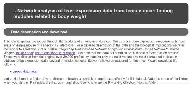
整个分析流程可以分为以下几个步骤
1. 数据预处理
这部分内容包括以下4个部分
- 读取基因表达量数据
- 对样本和基因进行过滤
- 读取样本表型数据
- 可视化样本聚类树和表型数据
官方的示例数据是一个小鼠的芯片表达谱数据,包含了135个雌性小鼠的数据,在提供的表达谱数据中,除了探针ID和样本表达量之外,还有额外的探针注释信息,在读取原始数据时,需要把多余注释信息去除,代码如下
# 读取文件
options(stringsAsFactors = FALSE)
femData = read.csv("LiverFemale3600.csv")

# 去除多余的注释信息列
datExpr0 = as.data.frame(t(femData[, -c(1:8)]))
names(datExpr0) = femData$substanceBXH
rownames(datExpr0) = names(femData)[-c(1:8)]
对于基因的表达量数据,需要进行过滤,对于基因而言,可以过滤缺失值或者低表达的基因,对于样本而言,如果该样本中基因缺失值很多,也需要过滤,WGCNA内置了一个检验基因和样本的函数,通过该函数可以进行一个基本过滤,代码如下
gsg = goodSamplesGenes(datExpr0)
if (!gsg$allOK) {
datExpr0 = datExpr0[gsg$goodSamples, gsg$goodGenes]
}
goodSamples和goodGenes就是需要保留的基因和样本。基础过滤之后,还可以看下是否存在离群值的样本,通过样本的聚类树进行判断,代码如下
pdf(file = "sampleClustering.pdf", width = 15, height = 10);
par(cex = 0.6);
plot(sampleTree,
  main = "Sample clustering to detect outliers",
  sub="", xlab="", cex.lab = 1.5,
  cex.axis = 1.5, cex.main = 2)
dev.off()
生成的图片如下
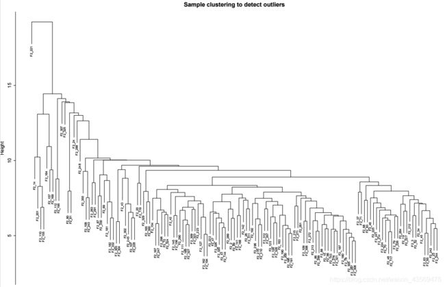
从图上可以看出,F2_221 这个样本和其他样本差距很大,可以将该样本过滤掉。代码如下
clust = cutreeStatic(
  sampleTree,
  cutHeight = 15,
  minSize = 10)

keepSamples = (clust==1)
datExpr = datExpr0[keepSamples, ]
nGenes = ncol(datExpr)
nSamples = nrow(datExpr)
表型数据中也包含了不需要的列,而且其样本比表达谱的样本多,需要根据表达谱的样本提取对应的表型数据,代码如下
# 读取文件
traitData = read.csv("ClinicalTraits.csv")

# 删除多余的列
allTraits = traitData[, -c(31, 16)]
allTraits = allTraits[, c(2, 11:36) ]

# 报纸和表达谱的样本一致
femaleSamples = rownames(datExpr)
traitRows = match(femaleSamples, allTraits$Mice)
datTraits = allTraits[traitRows, -1]
rownames(datTraits) = allTraits[traitRows, 1]
表达谱数据和表型数据准备好之后,可以绘制样本聚类树和表型的热图,代码如下
# 由于去除了样本,重新对剩余样本聚类
sampleTree2 = hclust(dist(datExpr), method = "average")

traitColors = numbers2colors(datTraits, signed = FALSE)

plotDendroAndColors(
  sampleTree2,
  traitColors,
  groupLabels = names(datTraits),
  main = "Sample dendrogram and trait heatmap")
上版部分为样本的聚类树,下班部分为样本对应的表型的热图,顺序和聚类树中的顺序一致,表达量从低到高,颜色从白色过渡到红色,灰色代表缺失值。
2. 构建共表达网络,识别modules
在构建共表达网络时,将基因间的相关系数进行乘方运算来表征其相关性,首先需要确定乘方的值,代码如下
# 设定一些列power梯度

powers = c(c(1:10), seq(from = 12, to=20, by=2))
sft = pickSoftThreshold(datExpr, powerVector = powers, verbose = 5)
在sft这个对象中保存了每个power值计算出来的网络的特征,结构如下
> str(sft)
List of 2
$ powerEstimate: num 6
$ fitIndices   :'data.frame':    15 obs. of  7 variables:
  ..$ Power         : num [1:15] 1 2 3 4 5 6 7 8 9 10 ...
  ..$ SFT.R.sq      : num [1:15] 0.0278 0.1264 0.3404 0.5062 0.6807 ...
  ..$ slope         : num [1:15] 0.345 -0.597 -1.03 -1.422 -1.716 ...
  ..$ truncated.R.sq: num [1:15] 0.456 0.843 0.972 0.973 0.94 ...
  ..$ mean.k.       : num [1:15] 747 254.5 111 56.5 32.2 ...
  ..$ median.k.     : num [1:15] 761.7 250.8 101.7 47.2 25.1 ...
  ..$ max.k.        : num [1:15] 1206 574 324 202 134 ...
其中powerEstimate就是最佳的power值,fitIndices保存了每个power对应的网络的特征。
代码如下
plot(
  sft$fitIndices[,1],
  -sign(sft$fitIndices[,3])*sft$fitIndices[,2],
  xlab="Soft Threshold (power)",
  ylab="Scale Free Topology Model Fit,signed R^2",type="n",
  main = paste("Scale independence")
)

text(
  sft$fitIndices[,1],
  -sign(sft$fitIndices[,3])*sft$fitIndices[,2],
  labels=powers,
  cex=0.9,
  col="red"
)


abline(h=0.90, col="red")
生成的图片如下
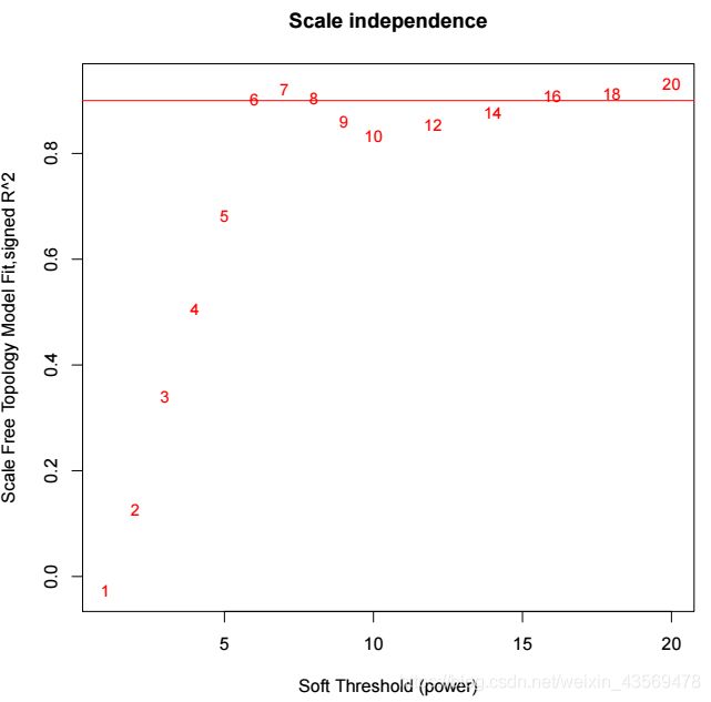
sft$fitIndices 保存了每个power构建的相关性网络中的连接度的统计值,k就是连接度值,可以看到,对于每个power值,提供了max, median, max3种连接度的统计量,这里对连接度的均值进行可视化,代码如下
plot(
sft$fitIndices[,1],
sft$fitIndices[,5],
xlab="Soft Threshold (power)",
ylab="Mean Connectivity",
type="n",
main = paste("Mean connectivity")
)

text(
sft$fitIndices[,1],
sft$fitIndices[,5],
labels=powers,
cex=cex1,
col="red"
)
生成的图片如下

确定好power值之后,可以直接构建相关性网络
net = blockwiseModules(
datExpr,
power = sft$powerEstimate,
TOMType = "unsigned",
minModuleSize = 30,
reassignThreshold = 0,
mergeCutHeight = 0.25,
numericLabels = TRUE,
pamRespectsDendro = FALSE,
saveTOMs = TRUE,
saveTOMFileBase = "femaleMouseTOM",
verbose = 3)
net对象中保存了所有相关性网络和module的结果,可以将基因的聚类树和对应的module进行可视化,代码如下
mergedColors = labels2colors(net$colors)

plotDendroAndColors(
  net$dendrograms[[1]],
  mergedColors[net$blockGenes[[1]]],
  "Module colors",
  dendroLabels = FALSE,
  hang = 0.03,
  addGuide = TRUE,
  guideHang = 0.05
)
生成的图片如下

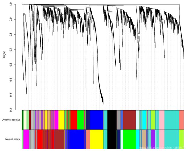
上方为基因的聚类树,聚类时的距离为1-TOM值,下方为基因对应的modules。
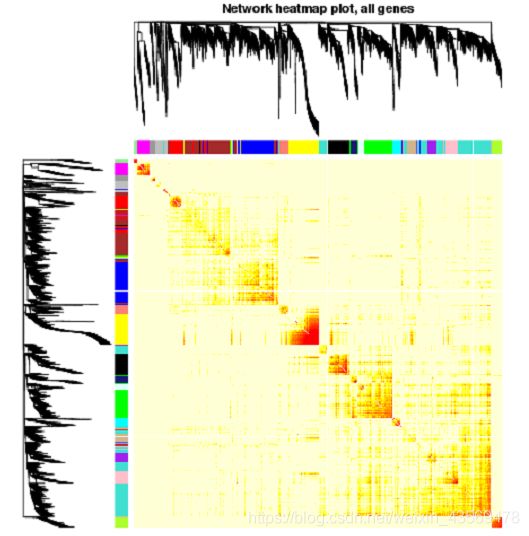
类似的,还可以结合基因间的距离,即1-TOM值,用热图展示,代码如下
geneTree = net$dendrograms[[1]]
moduleColors = labels2colors(net$colors)
dissTOM = 1 - TOMsimilarityFromExpr(
  datExpr,
  power = sft$powerEstimate)
plotTOM = dissTOM ^ 7
diag(plotTOM) = NA
TOMplot(
  plotTOM,
  geneTree,
  moduleColors,
  main = "Network heatmap plot, all genes"
)
生成的图片如下
在前面我们提到过,在识别module的过程中共,首先用dynamicTreeCut识别modules, 然后根据Module eigengene间的相关性合并modules,net`这个对象中保存了合并前和合并后的modules, 可以将二者画在同一张图上,可视化代码如下
unmergedColors = labels2colors(net$unmergedColors)
mergedColors   = labels2colors(net$colors)

plotDendroAndColors(
  net$dendrograms[[1]],
  cbind(unmergedColors[net$blockGenes[[1]]], mergedColors[net$blockGenes[[1]]]),
  c("Dynamic Tree Cut" , "Merged colors"),
  dendroLabels = FALSE,
  hang = 0.03,
  addGuide = TRUE,
  guideHang = 0.05
)
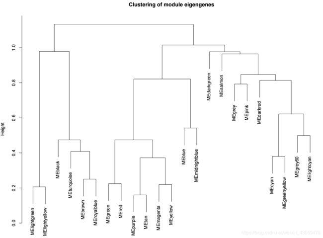
对于合并前的modules, 其相关性分析的结果可视化如下
unmergedColors = labels2colors(net$unmergedColors)

MEList = moduleEigengenes(datExpr, colors = unmergedColors)
MEs = MEList$eigengenes

MEDiss = 1-cor(MEs)

METree = hclust(as.dist(MEDiss), method = "average")

plot(METree,
     main = "Clustering of module eigengenes",
     xlab = "",
     sub = "")
生成的图片如下
对于每个module而言,我们希望知道该module下对应的基因,提取方式如下
> moduleColors = labels2colors(net$colors)
> unique(moduleColors)
[1] "grey"         "turquoise"    "grey60"       "yellow"       "tan"
[6] "green"        "red"          "black"        "blue"         "midnightblue"
[11] "cyan"         "magenta"      "salmon"       "lightgreen"   "brown"
[16] "purple"       "pink"         "greenyellow"  "lightcyan"
> head(names(datExpr)[moduleColors=="red"])
[1] "MMT00000159" "MMT00000793" "MMT00000840" "MMT00001154" "MMT00001245"
[6] "MMT00001260"
同样我们也可以提取module对应的基因表达量数据,绘制热图, 代码如下
which.module="red"
plotMat(
t(scale(datExpr[,moduleColors==which.module ]) ),
nrgcols=30,
rlabels=F,
rcols=which.module,
main=which.module,
cex.main=2
)
3. 筛选与表型相关的modules
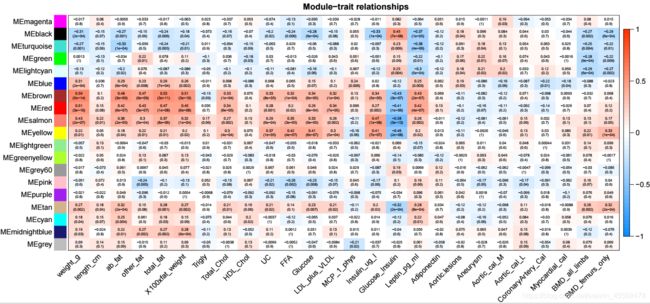
本质上是计算module的ME值与表型的相关系数,代码如下
nGenes = ncol(datExpr)
nSamples = nrow(datExpr)

MEs0 = moduleEigengenes(datExpr, moduleColors)$eigengenes
MEs = orderMEs(MEs0)
moduleTraitCor = cor(
MEs,
datTraits,
use = "p"
)

moduleTraitPvalue = corPvalueStudent(
moduleTraitCor,
nSamples
)
可以对module和表型间的系数的结果进行可视化,代码如下
textMatrix =  paste(
signif(moduleTraitCor, 2),
"\n(",
signif(moduleTraitPvalue, 1),
")",
sep = ""
)

dim(textMatrix) = dim(moduleTraitCor)

labeledHeatmap(
Matrix = moduleTraitCor,
xLabels = names(datTraits),
yLabels = names(MEs),
ySymbols = names(MEs),
colorLabels = FALSE,
colors = blueWhiteRed(50),
textMatrix = textMatrix,
setStdMargins = FALSE,
cex.text = 0.5,
zlim = c(-1,1),
main = paste("Module-trait relationships")
)
生成的图片如下
指定一个我们感兴趣的表型,可以得到与其相关性最高的module, 代码如下
> which.trait <- "weight_g"
> moduleTraitCor[, which.trait]
> moduleTraitCor[, which.trait]
     MEmagenta        MEblack    MEturquoise        MEgreen    MElightcyan
  -0.017418109   -0.312679561   -0.272907078    0.001339804   -0.128053858
        MEblue        MEbrown          MEred       MEsalmon       MEyellow
   0.314323101    0.591340840    0.509942529    0.432058666    0.219900538
  MElightgreen  MEgreenyellow       MEgrey60         MEpink       MEpurple
  -0.057215182   -0.022394396   -0.016705204   -0.051495573   -0.021167541
         MEtan         MEcyan MEmidnightblue         MEgrey
   0.269827166    0.181595161    0.193569095    0.089702947
以上结果中,和weight_g最相关的为module为MEred,当然也可以自己指定一个阈值,筛选出多个候选的modules。在WGCNA中,对于基因定义了GS值,表征基因和表型之间的相关性,对于module而言,也可以用所有基因GS绝对值的平均数来表征该module与表型之间的惯性,代码如下
moduleColors = labels2colors(net$colors)
which.trait <- "weight_g"
y <- datTraits[, which.trait]
GS <- as.numeric(cor(y ,datExpr, use="p"))
GeneSignificance <-  abs(GS)
ModuleSignificance <- tapply(
GeneSignificance,
moduleColors, mean, na.rm=T)
plotModuleSignificance(GeneSignificance, moduleColors)
生成的图片如下
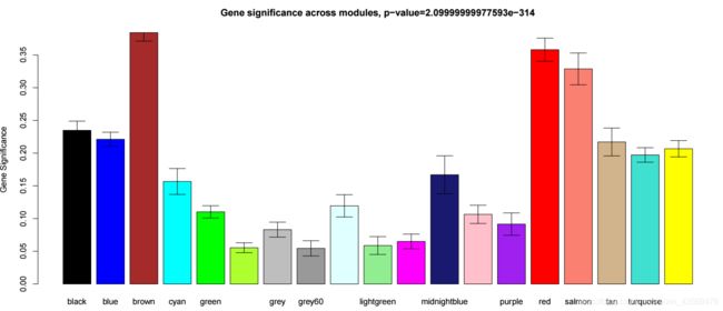
可以看到brown, red这两个模块和体重相关。对于ME和某一表型而言,还可以将数据合并,聚类展示,代码如下
weight <- datTraits[, which.trait]
MEs0 = moduleEigengenes(datExpr, moduleColors)$eigengenes
MEs = orderMEs(MEs0)
MET = orderMEs(cbind(MEs, weight))


par(mar = c(4, 2, 1, 2), cex = 0.9)
plotEigengeneNetworks(
MET, "",
marDendro = c(0,4,1,2),
marHeatmap = c(3,4,1,2),
cex.lab = 0.8,
xLabelsAngle = 90
)
4. 筛选关键基因
筛选出与表型高相关的modules之后,还可以对modules下的基因进行进一步筛选,主要根据GS值和MM值,代码如下
datKME = signedKME(
datExpr,
MEs,
outputColumnName="MM.")

FilterGenes= abs(GS1)> .2 & abs(datKME$MM.brown)>.8
筛选出候选基因后,可以进行下游的功能富集分析,使用clusterProfiler等R包,进一步挖掘功能。
5. 导出module数据, 绘制网络图
可以导出指定modules对应的基因共表达网络,方便可视化,代码如下
TOM = TOMsimilarityFromExpr(datExpr, power = 6)
modules = c("brown", "red")
probes = names(datExpr)
inModule = is.finite(match(moduleColors, modules));
modProbes = probes[inModule];
modTOM = TOM[inModule, inModule];
dimnames(modTOM) = list(modProbes, modProbes)

cyt = exportNetworkToCytoscape(
modTOM,
edgeFile = paste("CytoscapeInput-edges-", paste(modules, collapse="-"), ".txt", sep=""),
nodeFile = paste("CytoscapeInput-nodes-", paste(modules, collapse="-"), ".txt", sep=""),
weighted = TRUE,
threshold = 0.02,
nodeNames = modProbes,
nodeAttr = moduleColors[inModule]
)
最终会生成以下两个文件,可以导入cytoscape进行绘图
- CytoscapeInput-edges-brown-red.txt
- CytoscapeInput-nodes-brown-red.txt
当然也支持导出VisANT软件支持的格式,详细用法请参阅官网的帮助文档。
扫描关注微信号,更多精彩内容等着你!
![]()

