OpenCV+aruco 生成标定格与相机位姿计算

仅用于记录自己使用aruco过程中遇到的问题与解决方法。

0. 参考资料

github一个参考:https://github.com/opencv/opencv_contrib/blob/master/modules/aruco/samples/create_board.cpp
opencv aruco教程(但有问题):https://docs.opencv.org/4.5.3/db/da9/tutorial_aruco_board_detection.html
opencv docs:https://docs.opencv.org/3.2.0/d9/d6a/group__aruco.html#gaa871fca5f7f75f0e94deba8c417a296e

1. 编译aruco库

需要下载opencv对应的contrib模块,然后编译opencv时指定extra module。可以把其他不相关的module直接在contrib中删除。

编译后,将libaruco.so等复制到对应的路径。

代码编译时,CMakeLists.txt需link到libaruco,原始的${OpenCV_LIBS}没有包含这个库。

2. 生成Grid

aruco可以检测单独的mark,也可以检测一个阵列,进行相机标定或更精确的相机定位。所以需要首先生成Grid。所采用的代码如下:

#include 
#include 
#include "opencv2/opencv.hpp"
#include "opencv2/aruco.hpp"

using namespace std;
using namespace cv;

int main(int argc, char **argv){

    Mat markerImage;
    cv::Ptr<aruco::Dictionary> dict = aruco::getPredefinedDictionary(aruco::PREDEFINED_DICTIONARY_NAME(aruco::DICT_4X4_100));
    
    // board: aruco map. create(x_num, y_num, size(m), gap, diction, (index=1))
    cv::Ptr<aruco::GridBoard> board = aruco::GridBoard::create(7, 10, 0.04, 0.01, dict);

    Mat img;
    board->draw(Size(7000, 10000), img, 100);      // 上一步设置的大小没有太多的意义,draw时和实际尺寸无关
    // board->draw: 第三册参数为:marginSize, minimum margins (in pixels) of the board in the output image 

    imshow("img", img);
    imwrite("/home/larrydong/Desktop/aruco.png", img);
    return 0;
}

说明:
dictionary指mark的形式,对应4X4_100表示用内部长宽为4x4的mark,100为这个字典的大小是100,即从0-99。如果生成的阵列超过100,可以选用250/1000这种。

Board是mark构成的一个板子,不要求必须是标注的阵列形式,指定每个mark的坐标即可生成一个board。但一般采用阵列形式。

GridBoard是便捷生成一个阵列,在create时有六个参数如下:
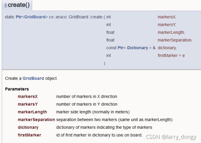
OpenCV+aruco 生成标定格与相机位姿计算_第1张图片需要注意虽然给定了markerLength,但这个数值基本没有用。只需要保证length和separation的比例即可。
最后的firstMarker为整个grid的起始的id是多少,比如设置为5,那么就是5-75。

之后需要进行绘制draw(),参数如下:
OpenCV+aruco 生成标定格与相机位姿计算_第2张图片首先指定图片的size,之后margin是最小的marker需要多少个像素。如果最小值*阵列的长宽超过了图片的size,运行会报错。

但这里图片的size如果远大于设定的最小margin,会自动缩放grid的大小,并放在图片中间。所以之前的markerLength并没有什么用。

3. 检测与相机定位

#include 
#include 
#include "opencv2/opencv.hpp"
#include "opencv2/aruco.hpp"

using namespace std;
using namespace cv;

int main(void){
    Mat inputImage = imread("/home/larrydong/output/eb_record/aruco/0.bmp", 1);
    if(inputImage.empty()){
        cout << "Error. Cannot load images" << endl;
        return -1;
    }

    // load intrinsics
    cv::Mat cameraMatrix, distCoeffs;
    
    FileStorage f_calib;
    f_calib.open("/home/larrydong/eb_record_ws/src/HIKROBOT-MVS-CAMERA-ROS/config/calib.yaml", FileStorage::READ);
    if(!f_calib.isOpened()){
        cout << "Cannot open f_calib" << endl;
        return -1;
    }
    f_calib["intrinsics"] >> cameraMatrix;
    f_calib["distortion_coeffs"] >> distCoeffs;

    Ptr<aruco::Dictionary> dict = aruco::getPredefinedDictionary(aruco::PREDEFINED_DICTIONARY_NAME(aruco::DICT_4X4_100));
    // board: aruco map. create(x_num, y_num, size(m), gap, diction, (index=1))
    Ptr<aruco::GridBoard> board = aruco::GridBoard::create(7, 10, 0.0272, 0.00518, dict);   // real distance in meters.
    vector<int> markerIds;         // detected ids.
    vector<vector<Point2f>> markerCorners;
    aruco::detectMarkers(inputImage, board->dictionary, markerCorners, markerIds);

    if(markerIds.size() > 0) {      // if at least one marker detected
        aruco::drawDetectedMarkers(inputImage, markerCorners, markerIds);
        
        cv::Vec3d rvec, tvec;
        int valid = cv::aruco::estimatePoseBoard(markerCorners, markerIds, board, cameraMatrix, distCoeffs, rvec, tvec);        
        if(valid){
            aruco::drawAxis(inputImage, cameraMatrix, distCoeffs, rvec, tvec, 0.1);
            cout << "rvec: " << rvec << endl;
            cout << "tvec: " << tvec << endl;
        }
        imshow("aruco", inputImage);
    }
    else{
        cout << "cannot find anymarks" << endl;
    }
}

检测时,传入一张图片,采用detectMarkers函数。函数需要传入图像、对应的dictionary是什么样的,输出检测到的marker交点,和对应marker的id。需要注意,这里的dictionary对应的marker的大小,应该是打印出来的实际尺寸,并非生成时指定的理论值。

检测后,能够获取所有marker的角点和id。之后进一步通过检测到的角点确定相机的位姿estimatePoseBoard,此时需要知道之前给定的dictionary的markder大小,以及相机的内参和畸变。

也可以再画出来坐标轴drawAxis。需要注意,Board的原点定义为“最左下角的marker”,z向相机方向。所以在标定时需要保证marker的原点一直在左下角。和marker的id没有任何卵关系。

A Board of marker has a single world coordinate system which is defined by the board layout. The coordinate system in a Grid Board is positioned in the board plane, centered in the bottom left corner of the board and with the Z pointing out

小结

一天的时间基本搞清楚了这个aruco。网上的资料真的乱七八糟,还是自己瞎凑多试整的明白。

你可能感兴趣的:(OpenCV,opencv)