THE PBR GUIDE - PART 2——Practical Guidelines For Creating PBR Textures
https://academy.substance3d.com/courses/the-pbr-guide-part-2
in part 1, we defined PBR from a technical and theoretical standpoint. in part 2, we will discuss the pratical application of authoring PBR textures and provide a set of guidelines that are based on the foundations established in part 1.
We will begin by redefining PBR from an artistic perspective. From there, we will address the principles of the metal/ roughness workflow. We will then follow up with the specular/ glossiness workflow and discuss the differences in the authoring methods. It is best to read through both workflows to get a full idea of the overall guidelines for authoring PBR textures.
In this guide, we will discuss workflows using the Substance toolset, but the principles discussed for map creation apply to any software used to create physically-based textures and materials.
Physically Based Rendering (PBR) is a methodology 方法论 rather than a hard standard. There are specific principles and guidelines, but no one true rule, which means there can be different implementations. The map types and workflow used can vary. A GGX BRDF is commonly used but there can be variation in the terms. Also, some implementations change the map names, even though their underlying usage remains the same.
In this part, we will discuss the two most common workflows, which are metal/roughness and specular/glossiness (Figure 16). The Substance toolset for authoring PBR maps, which is comprised of Substance Designer, Substance Painter and Substance B2M, supports both workflows. The Substance PBR shaders for metal/roughness and specular/ glossiness use GGX BRDF and do not use any value remapping for roughness/glossiness. However, if any custom remapping is needed, this can easily be implemented in Substance.

Figure 16: Metallic/Roughness and Specular/Glossiness workflows
Furthermore, custom shaders are supported in the Substance toolset, which means you can adapt Substance to any customized pipeline.
While both workflows have pros and cons in their implement-ation, one is not superior to the other. It is the underlying concepts and guidelines that will make the PBR maps you author accurate, rather than the workflow itself. The workflows represent the same data, but they implement it in different ways.
What is PBR?
Physically Based Rendering (PBR) is a method of shading and rendering that provides a more accurate representation of how light interacts with surfaces. It is referred to as Physically Based Rendering (PBR) or Physically Based Shading (PBS). Depending on what aspect of the pipeline is being discussed, PBS is usually specific to shading concepts and PBR is specific to rendering and lighting. However, both terms describe the process of representing assets from a physically accurate standpoint.
What are the benefits?
As artists, we can view the benefits of PBR from an artistic and production efficiency mindset:
-
PBR removes the guesswork of authoring surface attributes, such as specularity, since its methodology and algorithms are based on physically accurate formulas. It is therefore easier to create realistic-looking assets.
-
Assets will look accurate in all lighting conditions.
-
PBR provides a workflow for creating consistent artwork, even between different artists.
What does it mean for the artist?
As artists, we need to think differently about the maps that describe the attributes of a surface as advances in computer hardware and rendering allow us now to more closely simulate the physics of light.
We need to throw out the concepts of diffuse and specular maps from traditional rendering workflows because these maps only serve as workarounds for approximating light interaction with materials.
In PBR, the shader handles the heavy lifting of the rules of physics through energy conservation and BRDF while, as artists, we create maps that are guided by physical principles. The scientific aspects of PBR take the guesswork out of material values and allow us to spend more time on the creative aspects of texturing. While it is important to adhere to guidelines and author maps correctly, this doesn’t mean that we must now disregard our artistic intuition. It is the artistic perspective that truly brings character to a material, revealing its story through carefully crafted detail and expression. The physics of the process should never be the artist’s main concern. Just because we are working in a more physically accurate environment does not mean that we cannot create stylized art. For example, Disney’s physically-based reflectance model was designed to be a principled approach. That is, it was geared more towards art direction rather than a strictly physical model. It is important to know the principles and use the guidelines without being slaves to them.
As artists, we need to think differently about the maps that describe the attributes of a surface. There are new map types with rules and guidelines to follow.
Metal / Roughness Workflow
The metal/roughness workflow is defined through a set of channels, which are fed to a sampler in the PBR shader as textures. The maps specific to the metal/roughness workflow are base color, metallic and roughness (Figure 17). We will discuss each of these map types, which are common to both workflows. The PBR shader will also use ambient occlusion, normal and possibly height for parallax or displacement mapping (Figure 18)

Figure 17: Metallic/Roughness workflow

Figure 18: Height map and ambient occlusion as optional inputs to the shader
In the metal/roughness workflow, the reflectance value for metals is placed in the base color map along with the reflected color for dielectrics. The reflection at grazing angles 掠射角 is handled by the BRDF. A metallic map is used, which works like a mask to differentiate metal and dielectric data found in the base color map. The dielectric F0 values are not authored by hand as the shader handles them. When the shader sees black in the metal map, it treats the corresponding area in the base color map as dielectric and uses a 4% (0.04) reflectance value (Figure 19).

Figure 19: Black denotes non-metal and 0.04 (4%) reflectance is used
As we discussed in Part 1, the 4% value covers most common dielectric materials. It’s important to note that all values, such as dielectric F0, metal reflectance and brightness ranges for albedo color, are derived from actual measured data. As we look at each map type, we will talk about guidelines, which are based on measured data.
In Part 1, we discussed the notion of energy conservation where the light reflected off the surface will never be more intense than it was before it hit the surface. In terms of implementation, the shader typically handles the control of energy conservation. This is the case with Substance. With the metal/roughness workflow it is not possible to break the law of energy conservation. The diffuse (reflected color) and specular balance are controlled through the metallic mask, and so it is impossible to create a situation where the diffuse and specular can combine to reflect/refract more light than is initially received.
The reflectance value for metals are placed in the base color map along with the reflected color for dielectrics.
Dielectric F0
The F0 for common dielectric materials is typically set to 0.04 (linear) 4% reflective. In the metal/roughness workflow, this value is hardcoded in the shader. 在金属/粗糙度的工作流中,绝缘体的F0被设置为0.04,而且是在shader中硬编码的。
Some metal/roughness implementations, such as those found in the Substance toolset and Unreal Engine 4, have a specular control, which allows the artist to change the constant F0 value for dielectrics. In Substance, this output is labeled as ‘‘specularLevel’’ and is supplied by a texture sampler in the metal/roughness PBR shader. It represents the range of 0.0-0.08, as shown in Figure 20. This range is remapped in the shader to 0.0-1.0 where 0.5 represents 4% reflective.
有些金属/粗糙度的实现,比如subtance工具集和虚幻4中,有一个高光控制。这样artist就可以改变绝缘体的F0值。在substance中,它叫做specularLevel。在金属/粗糙度的shader中,使用采样器采样得到其值。它代表的是0.0-0.08这个范围。然后这个值被重映射到0.0-1.0中,也就是说0.04对应了0.5。
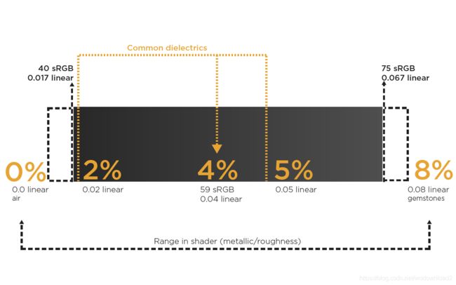
Figure 20: Specular level output represents the 0.0-0.08 range in shader for dielectric F0
If you need to manually set the F0 for a dielectric, you can do so using the specularLevel output in the Substance graph within Substance Designer or the specularLevel channel in Substance Painter as shown in figure 21. We will discuss F0 for dielectrics in depth in the specular/glossiness workflow, as you have full control over F0 in the specular workflow.
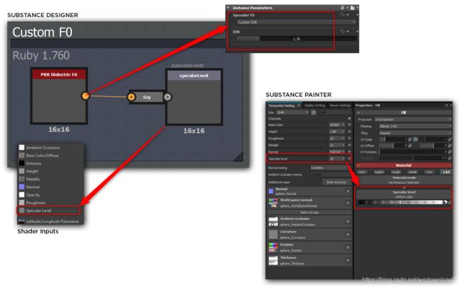
Figure 21: Set custom dielectric F0 using specular level channel
Figure 22: Base color contains reflected diffuse color and reflectance values for metals
Base Color (RGB – sRGB)
The base color map is an RGB map that can contain 2 types of data: diffuse reflected color for dielectrics and reflectance values for metals, as shown in Figure 22. The color that represents dielectrics represents reflected wavelengths, as discussed in Part 1. The reflectance values are present if an area is denoted as metal in the metallic map (white values).
Base color包含了两种类型的数据:绝缘体的漫反射的颜色,以及金属的反射值。绝缘体的漫反射的颜色,代表的是反射了那部分的波长颜色。而金属的反射值代表的是,如果金属贴图对应的区域的值为白色,表面这个区域是金属,那么base color中的对应部分代表是金属反射值。
Creation Guidelines
The base color map can be thought of as being somewhat flat in tonality. base color是一个基础色,基调,颜色比较平坦,无巨大的反差。
That is, its contrast is lower than that of a traditional diffuse map. 和平常的满发射图相比,它的变化比较小。It is inadvisable to have values that are too bright or too dark. 最好不要有明显的过暗和过亮的值。Objects tend to be much lighter in tone than we remember them as being. 物体的色调往往比我们记忆中的物体要浅得多。We can visualize this range in terms of the darkest substance being coal and the brightest being fresh white snow. Coal is dark, but it is not 0.0 black. The color values we choose need to stay within a brightness range.
我们可以把这个范围想象成最暗的物质是煤,最亮的物质是新鲜的白雪。煤是黑色的,但它不是0.0黑色。我们选择的颜色值需要保持在亮度范围内。
As regards to brightness ranges, we are mostly referring to dielectric reflected color. In Figure 23, you can see an example where the dirt value has fallen below the correct brightness range. For dark values, you should not go under 30-50 sRGB. The range for dark values could be more tolerant at 30 sRGB and stricter at 50 sRGB. For bright colors, you should not have any values that are higher than 240 sRGB (Figure23).
对于暗的值范围控制在30~50,而亮的值范围不能高于240。
![]()
Figure 23: Base color value ranges for dielectric materials (reflected color)
We stated that the base color contains data for reflected light in terms of dielectric materials, and thus it should be devoid of lighting information such as ambient occlusion. There can be exceptions for adding micro-occlusion in cases where the shader would not be able to represent this level of detail with only an ambient occlusion channel, as shown in Figure 24. However, if micro-occlusion is added to the map, it still needs to be governed by the brightness ranges.The values in the map that indicate the reflectance values for metals should be obtained from real-world measured values. These values are going to be around 70-100% specular, which we can map to an sRGB range of 180-255.
我们指导基础色,包含了数据,这个数据用术语来说就时电解质材质的反射光,所以应该去除掉环境遮蔽ambient occlusion。有一个例外,就是当shader不能没办法处理细节的时候,要加入微遮蔽。
Figure 24: The exception to the inclusion of lighting information in the base color is micro-occlusion
上面的这句话的意思,可以在base color中加入微遮蔽来提高细节,因为仅仅靠shader无法达到很好的细节效果了,这时候就只能借助base color来提高细节。
In the Substance PBR Utilities section, we will discuss tools that provide preset F0 values for common materials. The metal/roughness charts provided by Sébastien Lagarde are also great resources (Lagarde 2014).
Values that indicate the reflectance values for metals should be obtained from real-world measured values.
- Color represents albedo for non-metal materials and reflectance values for metals.
- Base color should be devoid of lighting information with the exception of micro-occlusion.
- Dark values should not be lower than 30 sRGB (tolerant range) to 50 sRGB (strict range).
- Bright values should not be higher than 240 sRGB.
- Reflectance for raw metal is going to be high, in the range of 70-100% specular, which we can map to 180-255 sRGB.
As you will read in the Metallic section below, the base color also can contain metal reflectance values. If dirt or oxidation 氧化 is added to the base color, this will cause the metal reflectance value to diminish to a range that cannot be considered as raw metal.
如果金属表面有灰尘后者是氧化了,那么金属的反射值就会减小,而不能视为纯金属。
The metallic map must also account for the addition of dirt or oxidation, and its value must be lowered in these areas to indicate that it is no longer considered as raw metal. In Figure 25 you can see that rusted metal is treated as dielectric and set to black in the metallic map. The dirt layer is also accounted for in the metallic map with transitional grey values. The metallic map may not always be binary i.e. 0.0 (black) or 1.0 (white) when there is a thin layer of a dielectric material such as dirt.
金属图也应该考虑灰尘和氧化,在这些地方的的值应该适当减小,以表面这个区域不再视为纯金属。
The metallic map operates in a manner similar to a mask, as it tells the shader how to interpret data found in the base color. 图25中可以看到,生锈的地方被当做电解质,对应的在金属贴图上应该是黑色表示。有灰尘的地方在金属贴图上用灰色的值表示。金属图可能不是二值的,比如有金属表面有很薄的灰尘,那么这个值应该是介于0到1之间的值。
Figure 25: The addition of dirt and/or oxidation must also be accounted for in the metallic map
Metallic (Grayscale – Linear)
The metallic map is used to define which areas of a material denote raw metal. As a grayscale map, it operates in a manner similar to a mask, as it tells the shader how it should interpret data found in the base color.
金属图用来表示那个区域是纯的金属,就好像灰度图一样,它的作用有点类似于遮罩,它可以告诉shader,如何利用金属图来解析base color中存放的数据。
Figure 26: Base color map contains reflectance values for raw metal as indicated by the metal map
The data in the metallic map does not contain real-world data that is directly used as material value. It simply describes to the shader which areas in the base color should be interpreted as reflected color (dielectric) and which areas denote metal reflectance values. In the metallic map, 0.0 (black – 0 sRGB) represents non-metal and 1.0 (white – 255 sRGB) represents raw metal. In terms of defining raw metal and non-metal, this metallic map is often binary: black or white, metal or non-metal. In practice, when the shader looks at the metal map and sees white, it then checks the corresponding areas in the base color map to get the reflectance values for the metal as shown in Figure 26.
这段话的意思和上面的一样,就是金属图用来告诉shader如何解析base color,如果非金属的值为0,纯金属的值为1。
Creation Guidelines
Metal surfaces have two important aspects relating to texturing: first, their reflectance values will be high in the range of 70-100% specular; second, some metals can be corroded. We will look at these two aspects individually as we discuss the creation guidelines.
创建金属的表面有两个准则:1、反射值很高,应该在70-100%之间;2、考腐蚀情况。
Metal areas that fall in this range will need to have a reflectance range of 70-100% reflective.
Raw Metal
The metal map is to be authored as 0 or 1, metal or not, and is used to define a raw, polished metal state. As a general guide, the grayscale range for raw metal will be defined as 235-255 sRGB in the metal map. Metal areas that fall in this range will need to have a reflectance range of 70-100% reflective in the base color map, which we can map to 180-255 sRGB as shown in Figure 27. Again, these values are based on real-world measured data.
Figure 27: Base metal will be defined as >= 235 sRGB in the metal map
Corroded or dielectric layer
When you weather a surface, you may need to consider that the metal is oxidized, or to compensate for other environmental aspects such as dirt and grime 污垢. In these cases, the metal needs to be treated as dielectric. The same is true for painted metal 喷漆金属 . If you look at painted metal where portions of the paint have been scratched or chipped away, the metal exposed is “raw” (white in the metallic map) and the paint is a dielectric layer (black in the metallic map), as shown in Figure 28.
Figure 28: Painted metal is treated as dielectric
The metallic map can represent a blended state between metal and non-metal that is represented by transitional gray values in the map. If the metallic map has gray values lower than 235 sRGB you need to lower the “raw” metal reflectance value in the base color. Think of a dirt layer that partially obscures portions of raw metal as shown in Figure 29. The dirt is dielectric. If you were to leave the metallic map at full white it would treat these dirt areas in the base color as the reflectance value for metal. The dirt color value is much lower than the value needed to represent the 70-100% reflectance for polished metals. By lowering the metallic map value in areas represented by the dirt, you create the appropriate blend between the dielectric and metal reflectance values.
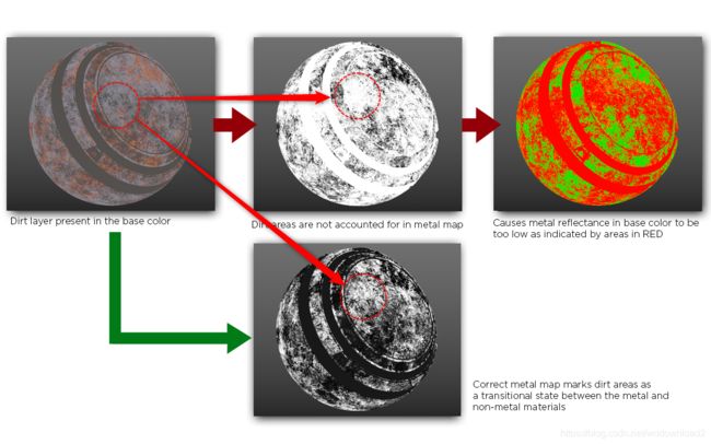
Figure 29: Grayscale range for metal will be defined as >= 235 sRGB in the metal map
The opacity of the dirt layer can indicate how much to lower the reflectance value in the base color. There are no hard-and-fast rules here. You are essentially moving from a high-reflectance surface (conductive) to a lower reflectance surface (dielectric). However, the degree to which this transition is taking place may vary.
The Substance toolset allows easy use of weathering effects, as well as control over how these effects will propagate to the channels through multi-channel support. Substance Designer and Substance Painter allow you to change parameters on a Substance effect generator, which will automatically adjust the channels that are controlled by the Substance effect.
For example, in Substance Designer you can use a Material Color Blend node to apply an effect such as dirt across multiple channels. On the Material Color Blend, you can control the dirt layer’s effect on metal by adjusting the metallic value slider, as shown in Figure 30.
Metal that is oxidized needs to be treated as dielectric, or rusted, metal. The same is true for painted metal
Figure 30: Material color blend. Lower metallic value indicates a thin layer of dirt (transitional state between dirt and metal
Black (0.0) is non-metal and white (1.0) is metal. There can be transitional grayscale values to account for oxidation or dirt.
If metal map has values lower than 235 sRGB, then the reflectance value needs to be lowered in the base color map
Roughness (Grayscale - Linear)
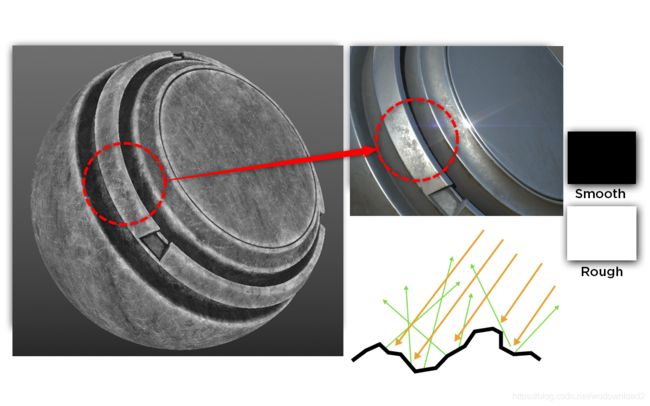
The roughness map describes the surface irregularities that cause light diffusion, as shown in Figure 31. As discussed in Part 1, the reflected direction will vary randomly based on the surface roughness. This changes light direction, but the light intensity remains constant. Rougher surfaces will have larger and dimmer-looking highlights. Smoother surfaces will keep specular reflections focused, which can appear to look brighter or more intense even though the same total amount of light is reflected.
Figure 31: The roughness map describes the surface irregularities that cause light diffusion
In this map, black (0.0) represents a smooth surface and white (1.0) represents a rough surface. The roughness map is the most creative map as it allows the artist to visually define the character of a surface. It allows you to creatively tell a story about the condition of a surface. What is its environment? Has it been handled with care or disregard? Has it been exposed to the elements? The condition of a surface tells a lot about its environment and thus relates to the overall design of the assets and worlds you are trying to create.
Roughness is a highly subjective area. You, the artist, are in full creative control. A good place to start with roughness is the normal map. The normal map will often contain key surface details that should also be represented in the roughness map.
粗糙度是个很主观的领域,美术有完全的掌控权。法线可以认为是粗糙度贴图的一钟。法线贴图包含了表面的关键细节,这些细节同样应该体现在粗糙度贴图上。
Creation Guidelines
Be creative and tell a visual story about the surface.
Resolution and Texel Density
A byproduct of using the metal/roughness workflow is that it can produce a white edge artifact, as shown in Figure 32. This issue also occurs in the specular/glossiness workflow. In that case, however, it is not nearly as visible because the effect is reversed: there is a black fringe instead of white, as shown in Figure 33.
使用金属/粗糙度贴图的一个副产品是,它可以产生一个白色的边效果。
而使用镜面/光滑度贴图的一个副产品是,它可以产生一个黑色的边效果。

Figure 32: A byproduct of using the metal/roughness workflow is that it can produce a white edge artifact
Figure 33: A byproduct of using the specular/glossiness workflow is that it can produce a dark edge artifact
This fringe 边 is due to texture interpolation, and is apparent in the transitional areas between materials where there is a sharp contrast between a dielectric material and a very bright metal. This is shown in Figure 34. With metal/roughness, the base color contains a brighter value for the metal reflectance that is interpolated with the non-metal diffuse color, which produces the white edge. With specular/glossiness, the diffuse map contains black since raw metal has no diffuse color. The black value is interpolated with the non-metal diffuse color, which in turn produces a black fringe.
在金属/粗糙度工作流中,base color的亮的部分被解释为非金属的反射,越亮表面漫反色的颜色越小,于是会产生白边。
在镜面/光滑度工作流中,diffuse map的黑色部分被解释为非金属的反射,越暗表面漫反射的颜色越小,于是会产生黑边。

Figure 34: Fringe is apparent in the transitional areas between materials
The document resolution and texel density have a direct impact on the visibility of edge artifacts. For example, if you use a hard edge brush to create the transitional areas between metal and non-metal, a low document resolution will still soften the edge and thus exacerbate the artifact. This low-resolution issue is also caused by UVs that are not scaled to provide an adequate texel density based on the document resolution. Providing a good texel density for UVs is the best method for minimizing any edge artifacts, as shown in Figure 35.
Figure 35: Providing a good texel density for UVs is the best method for minimizing any edge artifacts
In Figure 35, both texture sets use the same 2048-pixel resolution. However, the image on the right shows a poor UV layout with a low texel density.
The document resolution and texel density have a direct impact on the visibility of edge artifacts.
Creation Guidelines
Texel density and resolution impact the white edge that can appear in the metal/roughness workflow. To minimize artifacts, make sure that your UVs provide an adequate density to match the document resolution.
Pros and Cons of the Metal/Roughness Workflow
Pros
- Can be easier to author and less prone to errors caused by supplying incorrect dielectric F0 data.
- Uses less texture memory, as metallic and roughness are both grayscale maps.
- Seems to be a more widely-adopted workflow.
Cons - No control over F0 for dielectrics in map creation. However, most implementations have a specular control to override the base 4% value.
- Edge artifacts are more noticeable, especially at lower resolutions
Specular / Glossiness Workflow
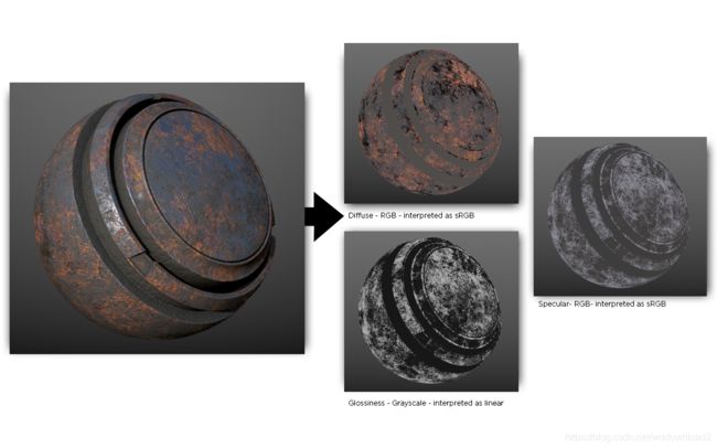
Just as with metal/roughness, the specular/glossiness workflow is defined through a set of maps which are fed as textures to a sampler in the PBR shader. The maps specific to the specular/glossiness workflow are diffuse, specular and glossiness (Figure 36).
Figure 36: Specular/glossiness workflow
Although the specular/glossiness workflow uses more familiar names such as diffuse and specular, it is important to make the distinction that these maps are not the same as their traditional counterparts. Substance uses the term diffuse, but some implementations may refer to diffuse as albedo. The PBR shader will also use ambient occlusion, normal and possibly height for parallax mapping which, as mentioned earlier, will be discussed in the Maps Common to Both Workflows section.
尽管镜面/光滑度工作流使用了很熟悉名字比如漫反射和镜面反射,但是这和传统意义上的漫反射和镜面反射贴图是有点区别的。substance使用术语diffuse,但是有些实现也叫做albedo。pbr着色器同样也会使用ao、法线、高度和视差图。
In this workflow, the reflectance values for metal and F0 for non-metal materials are placed in the specular map. With the specular/glossiness workflow, you have two RGB maps: one for diffuse color (albedo) and another for reflectance values (specular). With the specular map, you have control over the F0 for dielectric materials within the map itself.
在这个工作流中,金属反射值和F0(非金属材质)会存储在镜面反射图中。
As we stated in the metal/roughness workflow, the PBR shaders in Substance handle energy conservation. This becomes even more important in the specular/glossiness workflow as the specular map provides full control over the dielectric F0. This means that the map is more susceptible to containing incorrect values. For example, a white (1.0) diffuse and a white (1.0) specular value can combine to reflect/refract more light than was initially received, which in turn breaks the law of energy conservation. Consequently, when authoring the textures, the texture data would not correspond to the actual result.
As you will see, the data that the maps represent is the same as in the metal/roughness workflow. We will follow the same guidelines; however, the difference will be in how the maps are authored. The data will be placed in different maps, but we will follow the same principles. As stated earlier all values, such as dielectric F0, metal reflectance and brightness ranges for albedo color, are derived from actual measured data. As we look at each map type, we will discuss guidelines that are based on measured data. This section will not repeat the precise information covered in the metal/roughness section; rather, it will focus on the differences and where distinctions must be made for the specular/glossiness workflow.
Diffuse (RGB – sRGB)
As with the base color map from the metal/roughness workflow, the diffuse map contains albedo color. However, it doesn’t contain any reflectance values.
Creation Guidelines
The diffuse map is only albedo color. The areas that indicate raw metal will be black (0.0) as metal doesn’t have a diffuse color (Figure 37). In cases where oxidation has occurred, the metal area will contain color, as it is no longer treated as raw metal. The same is true for dirt or other effects that create a dielectric layer over the raw metal.
Figure 37: Areas that indicate raw metal will be black (0.0) because metal doesn’t have a diffuse color
The guidelines for the diffuse map in terms of tonality 音调 are the same as for the base color map. The exception is that if raw metal is present, then a value of 0.0 (black) is allowed and it is not governed by the guidelines for the darkness ranges
Color represents albedo for non-metal materials and black (0.0) for raw metal.
对于非金属,颜色代表漫反射的颜色;对于金属,这个颜色为黑色。
Base color should be devoid 缺乏 of lighting information except for micro-occlusion.
Dark values should not be lower than 30 sRGB (tolerant range) or 50 sRGB (strict range), except where raw metal is black.
Bright values should not be higher than 240 sRGB
Specular (RGB – sRGB)
The specular map defines the reflectance values for metal and the F0 for non-metal (Figure 38). This RGB map allows for different values for dielectric materials to be authored in the map. This is different from the metal/roughness workflow where dielectrics are hard-coded at 4% reflectivity and can be modified only through the ‘‘specularLevel’’ channel. Just as we covered in the metal/roughness workflow, the F0 data should be derived from real-world measured values. The F0 for dielectrics will be a darker value. The metal reflectance can be colored as some metals absorb light at different wavelengths. The F0 for both dielectrics and metals are authored in the RGB specular map.
The specular map allows different values for dielectric F0 to be authored in the map
Figure 38: The specular map defines the reflectance values for metal and the F0 for non-metal
Creation Guidelines
Since the specular map contains the F0 value for both metals and non-metals, we will break the map into a separate category for each material type.
Raw Metal
The F0 value should be based on real-world data. As we covered in the metallic map, the reflectance for raw metal will need to be lowered if there is oxidation or some layer that indicates non-metal. In the case of the specular/glossiness workflow, dirt or oxidation will raise the diffuse color for raw metal in the diffuse map and lower the reflectance value in the specular map, as shown in Figure 39. Also shown in Figure 39 is an example of a dirt layer on raw metal. The dirt in the specular map contains the appropriate F0 value for dielectric. In this case, we are using 0.04 or 4%.
Figure 39: Oxidation/dirt will raise diffuse color for raw metal and lower reflectance value in the specular map
Dielectric
The F0 for dielectric materials is authored in the specular map as well. Here you have full control over the F0 value, but it is important to use the correct data. As we discussed in Part 1, non-metals (insulators/dielectrics) are poor conductors of electricity. The refracted light is scattered and/or absorbed (often re-emerging from the surface) and thus these materials reflect a much smaller amount of light than metals. We stated that the value for common dielectrics would be around 2-5% based on the F0 as computed by the index of refraction (IOR). Except for gemstones, the F0 can be within the 0.02-0.05 (linear) range for common dielectric materials (Figure 40).
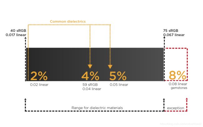
Figure 40: Common dielectric values fall within the 2-5% range
In terms of sRGB, we are looking at a scale of values between 40-75 sRGB, which overlaps the linear 0.02-0.05 (2-5%) range.
If you cannot find an IOR value for a specific material, you can assume 4% (0.04 - plastic). Gemstones are an exception and have a range of 0.05-0.17 (linear) as shown in Figure 40. In the metal workflow, the shader is mapped to a range of 0.0-0.08 (linear) when using the specularLevel channel as zero is needed to represent air, as shown in Figure 39.
The specular map contains F0 for dielectrics and the reflectance value for raw metal.
Dielectrics reflect a smaller amount of light than metals. The value for common dielectrics would be around 2-5%. In terms of sRGB, the values should be between sRGB 40-75, which overlap the 0.02-0.05 (linear) range.
Common gemstones fall within the 0.05-0.17 (linear) range.
Common liquids fall within the 0.02-0.04 (linear) range.
The reflectance value for raw metal will be high in the range of 70-100% specular, which we can map to 180-255 sRGB.
If you can’t find an IOR value for a specific material, you can use 4% (0.04 - plastic).
Glossiness (Grayscale - Linear)
The glossiness map describes the surface irregularities that cause light diffusion (Figure 41). In this map, black (0.0) represents a rough surface and white (1.0) represents a smooth surface. It is the inverse of the roughness map in the metal/roughness workflow. This map has the same artistic guidelines covered in the roughness section above.
Creation Guidelines
Once again, be creative and tell a visual story about the surface.
Figure 41: The glossiness map describes the surface irregularities that cause light diffusion
Resolution and Texel Density
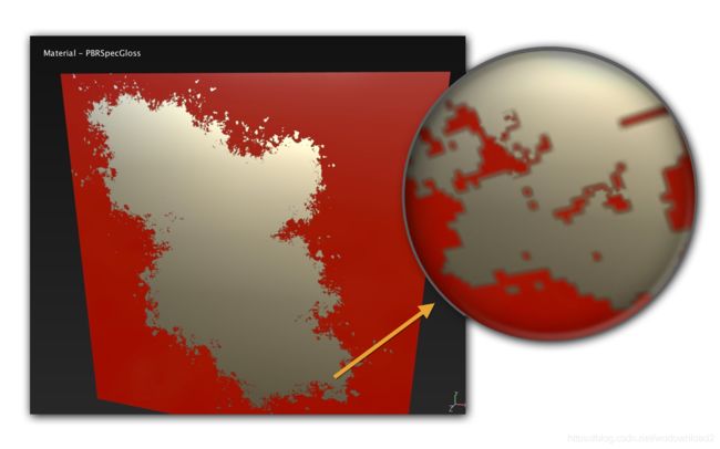
We discussed earlier how edge artifacts could appear in both workflows. This was discussed in depth in the metal/ roughness section, as the edge artifacts are more apparent in that workflow. We also mentioned that with specular/ glossiness, the diffuse map contains black since raw metal has no diffuse color. The black value is interpolated with the non-metal diffuse color, which produces a black fringe as shown again in Figure 42.

Figure 42: A byproduct of using the specular/glossiness workflow is that it can produce a dark edge artifact
Here again, the document resolution and texel density have a direct impact on the visibility of edge artifacts. If you use a hard edge brush to create the transitional areas between metal and non-metal, a low document resolution will still soften the edge and thus exacerbate the artifact. This low-resolution issue is also caused by UVs that are not scaled to provide an adequate texel density compared to the document resolution. Providing a good texel density for UVs is the best method for controlling this issue (Figure 43). The document resolution and texel density have a direct impact on the visibility of edge artifacts.

Figure 43: Providing a good texel density for UVs is the best method for minimizing any edge artifacts
Creation Guidelines
Texel density and resolution impact the black fringe that can appear in the specular/glossiness workflow. Be sure that your UVs provide an adequate density to match the document resolution in order to minimize artifacts.
Pros and Cons of the Specular/Glossiness Workflow
Pros
Edge artifacts are less apparent.
Control over dielectric F0 in the specular map.
Cons
Because the specular map provides control over dielectric F0, it is more susceptible to use of incorrect values. It is possible to break the law of conservation if handled incorrectly in the shader.
Uses more texture memory with an additional RGB map. 占用的内存比较多
Can be more confusing as it uses similar terminology to traditional workflows but requires different data.It also requires more knowledge of physically-based guidelines such as correct F0 for dielectrics, black for raw metal diffuse color and possible energy conservation if not handled in the shader. 容易引起混淆,和传统的工作流类似,但是需要不同的数据。需要更清楚的了解基于物理渲染的知识,比如说正确对于电解质的F0正确的使用。对于纯金属的漫反射颜色为黑色,还有尽可能的保证能量守恒。
Maps Common To Both Workflows
Ambient Occlusion (AO)
The ambient occlusion map defines how much of the ambient environment lighting is accessible to a surface point. It only affects the diffuse contribution and should not occlude the specular contribution. Some engines, such as Unreal Engine 4, have an option for screen space reflection to simulate local reflections.The best combination is to use AO with screen space reflections.
In Substance PBR shaders, the ambient lighting (generated by the environment map) is multiplied by the AO. The AO map is supplied by a texture sampler in the PBR shader and is an optional channel (Figure 44). The AO should not be baked into texture maps, but only supplied as its own channel to the shader.
AO only affects the diffuse contribution and should not occlude the specular contribution
Figure 44: The AO should not be baked into texture maps, but only supplied as its own channel to the shader
Creating Ambient Occlusion
In Substance Designer and Substance Painter, AO can be baked from a mesh or converted from a normal map using the integrated baking toolset. Also in both Substance Designer and Substance Painter you can use the HBAO node/filter to generate horizon-based ambient occlusion from a height input, which provides similar results to a raytraced bake, as shown in figure 45.
Figure 45: Using the HBAO node in Designer or filter in Painter produces similar results to a raytraced bake
Height
A height map is often used for displacement in rendering. It can be used for parallax mapping, helping to add more apparent depth and thus greater realism to normal and bump mapping. Substance uses the relief mapping parallax algorithm. The height is supplied by a texture sampler in the PBR shader and is also an option channel input to the PBR shader. In Substance Designer, you can use a parallax occlusion or tessellation shader (Figure 46). With Substance Painter, you can use a displacement channel to drive parallax occlusion.
Figure 46: The height is supplied by a texture sampler in the PBR shader and is also an option channel
Creating Height
Like AO, height can be baked in Substance Designer or Substance Painter from a mesh using the integrated baking toolset. In Substance Designer, you can use a node to convert height from a normal map (Figure 47). In Substance Painter you can directly paint height details as shown in figure 48.
In regard to using height with a realtime shader, it’s best to reduce the amount of high-frequency detail contained in the map. The height map should be designed to represent the overall silhouette of the forms used to displace the geometry. A good practice is to use a blurred version of the height to bring out the forms and reduce any high-frequency details. This will cause the normal map to provide the high-frequency details, and the height will displace the silhouette of the forms (Figure 49). If you are using height as displacement in a raytrace renderer, this high-frequency detail is needed.
其实高度图表示的就是物体的轮廓,通常用法线图转换得到一个高度图。

Figure 47: Use normal to height node to create a height map from normal data

Figure 48: Paint height details directly onto the mesh
Figure 49: The normal provided the high-frequency detail and the height the silhouette of the forms
Normal
The normal map is used to simulate surface details. It is an RGB map where each component corresponds to the X, Y and Z coordinates of the surface normal. It can be used to store the projected details of a high-resolution model to a low-resolution model. In the Substance toolset you can bake the normal or convert a height map to a normal map.
Creating Normal
A normal map can be baked in Substance Designer and Substance Painter from a mesh using the integrated baking toolset. In Substance Designer, you can use a normal node to convert height into a normal map as shown in Figure 50. In Substance Painter, you can paint normal data directly in the 3D viewport (Figure 51).
Figure 50: The normal node can create normal data from a height input
Figure 51: The normal channel can be used to paint normal data
Substance PBR Utilities
In this section, we will discuss several Substance utilities that can help with authoring PBR textures and setting correct reflectance values. These tools were built based on the principles and concepts covered in this guide.
Substance Designer
PBR Base Material
This node is a utility for creating a full base material and can be found under Material Filters > PBR Utilities as shown in Figure 52. It supports both metal/roughness and specular/glossiness workflows and provides common presets for raw metal materials. It also allows you to set the albedo if creating a non-metal. There are controls for roughness and glossiness depending on the workflow, which also have a grunge amount option. You can enable map inputs to feed in channels such as base color, normal or height.
Figure 52: PBR utility for creating a base material using preset values or custom map inputs
Dielectric F0
This node outputs F0 values for common dielectric materials (Figure 53) and can also be found under Material Filters > PBR Utilities. You can choose from preset values, and the node has an IOR input field that takes an IOR and computes the F0 value. It was designed for dielectric materials and can be used with the specular/glossiness workflow.

Figure 53: PBR utility for computing dielectric F0 values using presets or a custom IOR
Metal Reflectance
This node outputs reflectance values for common raw metal materials. Find it in the Substance Designer Library under Material Filters > PBR Utilities. You can choose from several preset metal values as shown in Figure 54.

Figure 54: PBR utility containing presets for metal reflectance values
PBR Metal/Roughness Validate
This node is designed to work with the metal/roughness workflow and is a utility which checks for incorrect values for the base color and metal maps (Figure 55). It can be found under Material Filters > PBR Utilities. The node outputs a heat map moving from red > yellow > green where red is incorrect and green/yellow is correct. With metal, it checks the corresponding F0 values in the base color for areas indicated as metal in the metallic map (greater than 235 sRGB). The heat map displays the range in which the F0 range may be too low. For the albedo, it checks to see if dielectric brightness ranges are correct.
PBR Safe Color
This node corrects values in the base color or diffuse maps, as shown in Figure 56. It makes sure that values fall within the corrected brightness ranges for dielectrics. It can be found in under Material Filters > PBR Utilities.
Figure 55: PBR utility that checks ranges for albedo/metal reflectance values and outputs a heat map to display correct/incorrect values

Figure 56: PBR utility that checks ranges for base color and diffuse
Conversion
BaseColor_metallic_roughness_converter
This node converts maps from the metal/roughness workflow to various renders and can be found under Material Filters > PBR Utilities.
Vray (GGX)
Corona
Corona 1.6
Redshift 1.x °
Arnold 4 (aiSurface) °
Arnold 4 (aiStandard) °
Renderman (pxrSurface)
° Arnold 5 supports the base color/metallic/roughness workflow. ° Redshift 2.x supports the base color/metallic/roughness workflow
Substance Painter
PBR Metal/Roughness Validate (filter)
This filter is designed to work with the metal/roughness workflow and is a utility which checks for incorrect values for the base color and metal maps (Figure 57). It is a free filter that can be downloaded from Substance Share.
The filter outputs a heat map moving from red > yellow > green where red is incorrect and green/yellow is correct. With metal, it checks the corresponding F0 values in the base color for areas indicated as metal in the metallic map (greater than 235 sRGB).
The heat map displays the range in which the F0 range may be too low. For the albedo, it checks to see if dielectric brightness ranges are correct.
To use this in Painter, import the filter into your Substance Painter project and tag it as a Filter or copy the filter to the Filter folder in your Shelf.

Figure 57: PBR utility that checks ranges for albedo/metal reflectance values and outputs a heat map to display correct/incorrect values
Substance Outputs and Rendering
A Substance material from Substance Source supports both the metallic/roughness and specular/glossiness workflows. These outputs can be used with physically-based real-time shaders such as those found in Unreal Engine 4 and Unity. The base color/metallic/roughness outputs can be used with raytraced renderers that support a metallic workflow such as Arnold. The specular/glossiness maps are used only for real-time shaders. Depending on the renderer, you may be able to use the base color/metallic/roughness outputs directly, or you may need to convert them.
Custom materials or resources you download from Substance Share may not have the appropriate outputs for a given renderer as they main only contain base color/metallic/roughness outputs, so it’s important to understand the type of material inputs your material will accept so that you can utilize the Substance material’s outputs correctly if they need to be converted.
For example, with Arnold 5 you can use the metallic/roughness outputs directly. However, with a Vray material, you will need to convert the metallic/roughness outputs to generate reflection and 1/IOR maps. Substance Painter supports several third-party renderer configurations, as shown in figure 58.

Figure 58: Painter ships with export configurations for popular renderers such as Arnold, Vray, Keyshot, Corona and Redshif
The goal for the Substance Integration plugins is to automatically convert Substance outputs to work with specific renderers. For example, the 3ds Max Substance plugin has presets for working with Arnold, Vray and Corona. Choosing the preset will automatically convert the Substance outputs for use with these renderers (Figure 59).

Figure 59: Using the Corona preset will create a Corona material and automatically convert the Substance outputs
For more information on working with third-party renderers with Substance Painter and Substance Designer (Substance Materials), please refer to our rendering documentation for Substance Integrations.
https://docs.substance3d.com/integrations/rendering-157352143.html
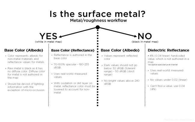
Figure 60: Is the surface metal? Metal/roughness workflow

Figure 61: Is the surface metal? Specular/glossiness workflow
Appendix - Charts
Is the surface metal?
It can be helpful to break down a surface into the metal or non-metal categories. It is often useful to begin the texturing process by first examining the material and asking whether or not it is metal. With this question, you can derive some guidelines for the texturing process as we have covered in this volume and as shown in Figures 60 and 61. Figure 60 uses the metal/roughness workflow and Figure 61 is specular/glossiness.
Reflectance Values
Figure 62 shows the F0 ranges for dielectrics as they relate to the Substance PBR shader in the metallic/roughness workflow. Dielectrics reflect a smaller amount of light than metals. The value for common dielectrics would be around 2-5%. For sRGB, the values should be between sRGB 40-75, which overlaps the 0.02-0.05 (linear) range.

Figure 62: Values for common dielectric F0 and metal reflectance values
In Figure 63, you can see both dielectric F0 and metal reflectance values. With metals, the specular range is within 70-100% and maps to the sRGB values of 180-255.

Figure 63: Values for dielectric F0 and metal reflectance values
Conversions from sRGB to linear were completed using the gamma 2.2 approximation. See the section on Linear Space Rendering in Part 1 for more details.
Correct/Incorrect Comparisons
In Figure 64, you can see an example of maps created correctly and incorrectly using the metal/roughness workflow. The dirt is marked as raw metal in the metallic map. Also, the metal reflectance value is set too low in the base color as it doesn’t reflect the 70-100% specular range.
Figure 64: Comparison of correct and incorrect maps – metal/ roughness
REFERENCES
Burley, B. (2012). Physically-Based Shading at Disney. [PDF] Available from:https:/disney-animation.s3.amazonaws.com/library/s2012_ pbs_disney_brdf_notes_v2.pdf [Accessed 5 July 2016].
Kwast, D. An Introduction to BRDF Models. [PDF] Available from:http://hmi.ewi.utwente.nl/verslagen/capita-selecta/CS-Jimenez-Kwast-Daniel.pdf [Accessed 5 July 2016].
Lagarde, S. (2014). ‘Dontnod Physically Based Rendering Chart for Unreal Engine,’ Sebastien Lagarde, blog post, April 14, 2014. Available from:https://seblagarde.wordpress.com/2014/04/14/dontnod-physically-based-rendering-chart-for-unreal-engine-4/ [Accessed 5 July 2016].
Lagarde, S. (2011). ‘Feeding a Physically-Based Shading Model’, Sebastien Lagarde, blog post, August 17, 2011. Available from:https://seblagarde.wordpress.com/2011/08/17/feeding-a-physical-based-lighting-mode/. [Accessed 5 July 2016].
Walter, B., Marschner, S., Li., H. and Torrance, K. (2007).Microfacet Models for Refraction through Rough Surfaces. [PDF] Eurographics Symposium on Rendering, 2007. Available from: https://www.cs.cornell.edu/~srm/publications/EGSR07-btdf.pdf [Accessed 5 July 2016].
Epic Games. (2004-2017). ‘Using Refraction’, Epic Games, UE4 Documentation, 2017. Available from:https://docs.unrealengine.com/latest/INT/Engine/Rendering/Materials/HowTo/Refraction/. [Accessed 5 July 2016]


