11-4 AEB 算法原理及系统组成
本专题旨在探讨如何利用仿真软件开发自动紧急制动系统 AEB,主要通过整理开发流程,实现从需求到验证的全流程掌握,为后续开发提供支持;同时,研究了如何在汽车自动驾驶仿真工具中开发自己的算法,并解决了从 ISO、E-CNAP、GB/T 以及交通法规等提炼出功能需求的问题,以快速实现原型模型的开发。本专题重点讲解了 AEB 的工作原理、系统/软件架构和需求、算法模型及实现、CCRs/CCRb/CCRm 建模与仿真、VRU-AEB-B/P/M 建模与仿真,同时还提供了测试用例,期待最终将 AEB 算法成功地产品化。
1、概述
1.1 快速原型模型 RPM
快速原型模型(Rapid Prototyping Model,RPM),是一种快速且有效地进行软件开发的模型。它可以帮助开发者能快速创建原型,并在创建的过程中进行测试、评估和反馈,以加速迭代和改进。
使用 RPM 模型开发 AEB 算法的步骤:
1. 确定需求和功能规格:定义 AEB 要求和目标,研究可用的传感器和算法,确定 AEB 的实现方法。
2. 创建原型:为系统创建一个初始版本,包括必要的硬件和软件。该原型应该能够实现 AEB 基本功能,例如检测前方障碍物和自动制动。在创建原型的过程中,可以使用各种开源软件和库来加速开发。
3. 迭代和测试:在原型的基础上,迭代地进行开发和测试。每次迭代可以加入新功能或修复现有问题。尽可能进行自动化测试,以加快开发速度并降低错误率。
4. 确定可行性和性能范围:在完成 AEB 功能的开发后,进行全面测试并确定其可行性和性能范围。将测试实际道路上的原型,并评估各方面的性能如制动距离和反应时间。
5. 验证和确认:在确定 AEB 功能达到要求后,进行最终确认,并准备发布系统。
总之,RPM 模型是一种快速且有效的软件开发模型,它可以帮助团队加速原型的创建、测试和改进。通过使用 RPM 模型,开发团队可以更快地交付高质量的成品,同时保持高效率和高可靠性。
1.2 自动紧急制动 AEB
自动紧急制动系统(Autonomous Emergency Brake,AEB)是一种由传感器模块、判断决策中心、制动模块和车辆人机交互模块共同构成的汽车主动安全技术。其通过雷达或/和摄像头等目标检测手段实时监测车辆前方机动车、电动车、有人骑行的自行车/摩托车及行人情况,判断出现潜在风险时系统将自动采取预警与制动措施,为安全出行保驾护航。
AEB 系统具有很大的安全潜力。Euro-NCAP 的研究表明,AEB 可以避免 27% 的交通事故,同时能大幅降低碰撞事故中人员受伤害的程度。因此,AEB 受到了各国政府和评价机构的高度重视,Euro-NCAP 从 2014 年开始把 AEB 场地测试结果纳入整车安全性评价体系,ECE 也发布了 AEB 法规。在中国,交通部于 2020 年发布《营运车辆自动紧急制动系统性能要求和测试规程》,要求商用车自 2021 年开始强制安装 AEB 系统;另一方面,乘用车 AEB 安装规范还迟迟没有落地。在此之前,C-NCAP、iVista 等国内测评规范对于 AEB 都有了明确的要求和评估机制。
1.3 AEB 系统主要作用
AEB 系统的主要作用是在行驶过程中及时发布碰撞危险预警,自动实施制动来避免碰撞事故的发生或减轻事故造成的损害。具体而言,AEB 系统在城市和高速工况下,通过以下几方面实现安全保障:
1. 碰撞预警:通过传感器和计算机对前方路况进行分析,及时发现可能发生碰撞的危险。
2. 自动制动:在碰撞危险发生时,自动触发制动系统,以便更快地减缓车速或完全停车,从而避免或减少碰撞事故的发生。
3. 提高安全性:AEB 技术可以提高车辆的安全性能,降低交通事故的发生率。
AEB系统可以在以下几种情况下能有效降低交通事故的发生率:
1. 前方车辆急停:AEB 系统可以确保车辆及时停下来,避免与前车发生追尾事故。
2. 行人出现:AEB 系统可以感知到 0.5m 高的行人进入车辆前方的区域,并表明是否会与行人相撞,从而尽可能减少事故伤害。
3. 不安全的车道变更:AEB 系统可以依靠车载传感器和决策系统,感测到驾驶员意图的不良驾驶行为,并触发自动紧急制动。
从追尾事故的统计数据表明,在现实世界中,31% 的驾驶员在发生物理碰撞之前无任何刹车动作;49% 的驾驶员尽管进行了刹车,但刹车力不足,没能避免追尾;最后 20% 的驾驶员实施了全力刹车,但为时已晚。
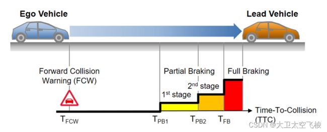
因此对应的,对于进行了全力刹车但刹车太晚的驾驶员,AEB 系统提供了 FCW 前碰撞预警功能以提醒驾驶员及早进行刹车;对于踩了部分刹车的驾驶员,AEB 系统提供了 EBA 紧急刹车辅助功能,帮助驾驶员放大其所施加的刹车力,保证有效刹车;而最后,对于根本没有刹车的驾驶员,AEB 系统将提供最后的保护屏障,代替驾驶员进行刹车。
实际上,AEB 功能在危险发生前期还提供了 Pre-fill 预填充功能,即其预先要求 ESC 建压,缩小刹车盘与刹车片之间的距离,使得在危险发生时,刹车力能够更加快速有效的施加在车轮上。另外,除了通过声音报警以及显示在仪表盘上的报警信息外,还可以通过座椅震动、安全带收紧,或通过无需额外成本的点刹进行驾驶员提醒。
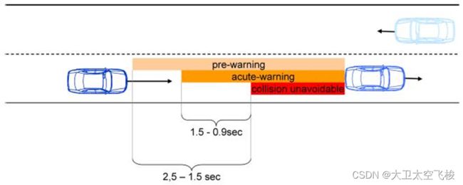
类似空战中空空/地空导弹的“不可逃逸区”,追尾事故也存在类似的“碰撞不可避免区”。根据统计,大约在进入此区域前 0.9-1.5s 内,可进行“点刹”提醒,而在进入此区域前 1.5-2.5s 内,可进行前碰撞的声光报警。
2. AEB 运行设计域 ODD
2.1 环境备件
白天
夜间
清晨
黄昏
2.2 天气条件
系统和传感器限制条件
雨天
雪天
雾天
冰雹
温度过高 -40 - 85
天气造成系统故障
摄像头故障,下雨天雨刮刚好刮过,雨滴到摄像头上;阳光正射
雷达故障
2.3 道路
道路类型
城市道路
城郊
道路条件
路面
半径
2.4 目标
类型
车辆
摩托车
行人
自行车
状态
静止
横穿
追尾
2.5 速度范围
8-120kph
2.6 驾驶员操作
制动
转向
油门
开关
挡位
2.7 车辆状态
车辆模式
充电
可以正常行驶
运输状态
展厅状态
休眠状态
底盘
ESC 状态
EPB 状态
Ibooster
SAS 状态
EPS 状态
传感器状态
轮速传感器-车速
方向盘转角传感器
制动踏板深度传感器
加速度深度
制动前温度
IMU 三个方向的线性加速度和旋转角速率
感知状态
正常
不正常
传感器故障
未标定
被遮挡
3. AEB 算法原理
3.1 AEB 算法实现原理
自动紧急制动(AEB)算法基于车辆感知和刹车系统控制,可以帮助避免或减轻碰撞。下面是 AEB 算法的原理。
1.AEB 算法的第一步是进行环境感知,通过使用雷达和摄像头等传感器检测车辆周围的环境。这些传感器可以捕捉到障碍物及其距离、速度和方向。然后,AEB 算法使用高级信号处理算法,如机器学习、人工智能等技术,对传感器数据进行识别和分析。
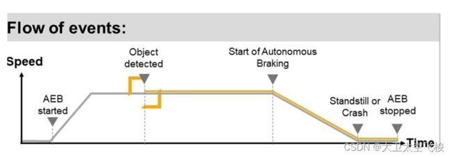
2. 接下来,AEB 算法决策机制根据传感器数据和预定义的规则,判断是否需要触发制动,以避免或减轻碰撞。如果检测到与前方车辆或障碍物的距离足够近或速度差异足够大,AEB 算法将触发紧急刹车,这时驾驶员应立即采取行动。如果驾驶员未采取行动,AEB 系统将自动施加制动。
3. 在制动操作阶段,AEB 算法将使用预制动和最大制动力两种操作方式。在预制动阶段,AEB 算法会施加轻微制动,以确保驾驶员的注意力被吸引。如果警告后的一段时间内仍未有反应,AEB 系统将使用最大制动力,以避免发生碰撞。
需要注意的是,AEB 算法并不对所有情况都有效。例如,在极端的案例下,即使进行最大制动力操作,也可能无法避免碰撞。但是 AEB 系统可以减少事故的严重程度,甚至在某些情况下完全避免碰撞。
总的来说,AEB 算法是一种可靠而有效的技术,可以减少意外损害和死亡。此外,AEB 算法的不断改进和优化,使得 AEB 系统成为新车型标配,带来更大的安全保障。
3.2 经典 AEB 算法
经典的 AEB 算法可以分为以下几种类型:
1.基于时间-距离的 TTC AEB 算法:该算法根据车辆与前方障碍物的距离和相对速度,计算出需要的制动时间,从而实现逐渐缩小与障碍物的距离,直至停止的效果。该算法简单易实现,但对于动态环境下的复杂交通情况可能不够准确。
2.基于车辆运动动力学的 AEB 算法:该算法考虑了车辆的质量、惯性等因素,结合障碍物的位置、速度和曲率等参数,计算出需要的制动力,从而更加准确地控制车辆的制动情况。但该算法需要对车辆动力学参数进行精细建模,计算逻辑复杂。
3.基于机器学习的 AEB 算法:该算法使用监督学习的方法,通过训练模型来预测在不同情况下需要施加的制动力。该算法受制于训练数据的质量和数量,要求对样本数据的选择和标注具有一定的经验。
4.基于传感器融合的 AEB 算法:该算法利用多个传感器(如摄像机、雷达、激光雷达等)采集的数据,进行相互验证和补充,从而提高对障碍物的准确感知,进而实现更加准确的制动控制。但该算法需要处理传感器融合和数据对齐的问题。
以上算法各有特点,不同的应用场景可以选择不同的 AEB 算法。
3.3 基于时间-距离的 AEB 算法
基于时间-距离的 AEB 算法(Time-to-Collision, TTC AEB)是最基本的 AEB 算法之一,也是最常用的一种。该算法通过计算车辆和前方障碍物之间的距离和相对速度,从而估算与障碍物相撞所需的时间,通过逐渐减小这个时间来控制车辆的制动行为。具体来说,该算法可以按照以下步骤实现:
1. 获取车辆与前方障碍物的距离和相对速度。
2. 计算障碍物到达车辆位置所需的时间(即 Time-to-Interception, TTI),公式为 TTI = Distance / Relative Velocity。其中 Distance 为车辆和障碍物之间的距离,Relative Velocity 为车辆和障碍物的相对速度。
3. 计算实际需要的制动距离,即 Brake Distance = Vehicle Speed * TTI,其中 Vehicle Speed 是车辆当前的速度。
4. 根据制动距离和车辆的制动性能,计算可以使用的最大制动力。通常,该制动力可以根据公式Braking Force = Vehicle Mass * Maximum Deceleration 来计算,其中 Maximum Deceleration 是车辆可以达到的最大减速度。
5. 根据最大制动力和实际需要制动力的大小,控制车辆的制动系统进行制动操作。
需要注意的是,上述算法仅考虑单个障碍物的情况,对于多个障碍物和动态环境,需要进行更加细致的求解和控制。基于时间-距离的 AEB 算法实现简单,计算量小,适用于大多数交通场景,但在复杂场景下可能存在误判和误操作的风险。为了提高AEB的可靠性和安全性,通常需要采用多种控制策略和算法进行综合判断和决策。
3.4 多个障碍物和动态环境预测
对于多个障碍物和动态环境,TTC AEB 算法需要进行更加细致的求解和控制。一些常见的方法包括:
1. 分别计算每个障碍物与车辆的时间-距离关系,并选取最短的时间作为 AEB 的行动依据。
2. 将障碍物分为静态和动态两类,对于静态障碍物直接使用时间-距离算法,对于动态障碍物,则需要考虑其运动轨迹和预测位置,并综合考虑多个障碍物的时间-距离关系进行决策。
3. 使用激光雷达等传感器获取车辆周围的三维点云数据,并进行障碍物检测、跟踪和预测,通过对障碍物轨迹和速度的预测来进行更加准确的应对,并可以实现对于遮挡和视野盲区的处理。
4. 采用机器学习等人工智能算法,通过对大量训练数据的学习和预测,来更加准确地判断障碍物运动和行为,从而做出更加可靠的决策和行动。
总之,针对复杂场景下的多个障碍物和动态环境,需要选择合适的传感器和算法,并进行综合处理和决策,以提高 AEB 的可靠性和安全性
要使 TTC AEB 算法更好地对多个障碍物和动态环境进行预测,可以考虑以下两种方法:
1. 综合考虑障碍物的相对速度和行驶方向。对于静态障碍物,车辆与其的时间-距离关系是比较稳定的,但是对于动态障碍物,需要预测它们的行驶方向和速度,以便更加准确地预测与其的时间-距离关系。一般情况下,动态障碍物都有自己的运动轨迹和速度,可以通过传感器获取其运动轨迹和速度,然后根据这些信息来综合预测其行驶方向和速度。
2. 使用动态预测算法。除了考虑障碍物的速度和行驶方向外,还可以使用动态预测算法来预测障碍物的运动轨迹和预计位置。一些常见的动态预测算法包括卡尔曼滤波、扩展卡尔曼滤波、粒子滤波等。这些算法可以根据障碍物的运动特性,不断地更新其位置和速度信息,从而预测其未来的行驶路线和位置,提供更加可靠的时间-距离预测结果。
3.5 经典动态轨迹预测算法
在L4级自动驾驶中,常用的动态轨迹预测算法如下:
1. 卡尔曼滤波法(Kalman Filter):最为常用的一种预测方法,将目标运动视为一种随机过程,并对其状态进行预测和估计。
2. 扩展卡尔曼滤波法(Extended Kalman Filter):在卡尔曼滤波的基础上,通过泰勒展开将非线性的运动模型线性化,以求得更为准确的状态估计值。
3. 粒子滤波法(Particle Filter):通过对概率分布进行采样,生成一组粒子来表示目标位置的不确定性。依据目标的运动特征和状态转移模型,对粒子进行逐一更新和筛选,得出目标的运动轨迹。
4. 决策树法(Decision Tree):利用机器学习的方法,基于数据集训练出预测模型,输入当前目标的特征向量(如位置、速度、加速度、方向等),输出目标的运动轨迹。
5. 配对关联度算法(Probabilistic Data Association Filter):将目标传感器数据与预测轨迹进行配对,并计算其关联度。通过历史数据和先验概率来调整关联度,以实现更为准确的轨迹预测。
3.6 城市工况下动态轨迹预测算法
在城市工况下,车辆和行人等目标物体的运动往往更加复杂和不规则,同时存在大量干扰和不确定性因素,如交通信号、突然变道、交通堵塞等。因此,需要选择适合城市工况下的动态轨迹预测算法。在实际应用中,以下算法更为常用:
1. 粒子滤波法:由于城市道路情况复杂多变,基于粒子滤波法的轨迹预测可更好地处理不确定性和非线性问题,如行人追踪等场景中应用广泛。
2. 决策树法:基于数据训练的决策树模型可更好地适应复杂的城市交通环境,并可处理多目标跟踪情况,如城市路口、交叉口中的车辆预测等。
3. 深度学习方法:包括循环神经网络等方法,适用于具有大量历史数据的场景,能够从大量数据中学习到潜在规律,并能够处理非线性关系,例如城市路段中的交通流预测、城市交通状况识别等。
综上所述,粒子滤波法和决策树法在城市工况下较为实用,粒子滤波法适用于多目标跟踪、不确定性问题等;决策树法适用于复杂的交通情况,如路口、交叉口等场景。
3.7 高速工况下动态轨迹预测算法
在高速工况下,车辆的速度相对较快,运动轨迹通常较为直线且稳定,干扰和不确定性因素相对较少。因此,需要选择适合高速工况下的动态轨迹预测算法。在实际应用中,以下算法更为常用:
1. 卡尔曼滤波法:适用于高速工况下的车辆跟踪和轨迹预测任务,可以较精确地对运动物体的位置和速度进行估计和预测,如高速公路上的车辆跟踪等。
2. 双门限模型法:在高速行驶中,车辆之间的距离近乎恒定,因此基于双门限模型的轨迹预测算法可以对车辆行驶的方向和速度进行准确的预测,如高速公路上的车辆跟踪和碰撞预警等场景。
3. 长短时记忆网络(LSTM)方法:LSTM 模型适合对历史轨迹模式进行建模,适合于需要对车辆行为进行较长期预测,如高速公路上的整体交通流预测、城市间高速公路车辆跟踪等。
综上所述,卡尔曼滤波法、双门限模型法和 LSTM 方法都适用于高速工况下的动态轨迹预测,其中,卡尔曼滤波法和双门限模型法适用于快速高速行驶的车辆跟踪和预测任务;LSTM 方法适合长期交通流预测等任务。
3.8 动态轨迹预测进阶算法
LSTM(长短时记忆网络)算法是一种适用于序列数据建模和预测的深度学习算法,已被广泛用于交通流预测任务中。但是,近年来在交通流预测中也涌现出一些新的算法,以下是几种可能取代LSTM的算法:
1. Transformer模型:Transformer 是一种以自注意力机制为基础的模型,其在自然语言处理领域中取得了很好的成果,并且也逐渐被应用于交通流预测领域。相比于 LSTM,Transformer 模型的预训练和泛化能力更强,预测效果更好。
2. GAN模型:对于交通流预测任务,可使用生成对抗网络(GAN)模型。它可以生成符合实际情况的交通流数据,并以此来帮助交通流预测。这种方法可以提高预测准确度和稳定性。
3. 图卷积神经网络(GCN)模型:图卷积神经网络是一种应用于图数据建模和预测的神经网络模型,也可以用于交通流预测模型的训练。在构建城市道路网络图后,可使用 GCN 模型来运算路网的特征向量,然后以此为预测流量的依据,相比于 LSTM,GCN 模型能够更好地捕获道路结构零散、复杂的关系,并且提供较强的精度。
总之,Transformer、GAN 模型和 GCN 模型在交通流预测中均有优异表现,同时,它们可以很好地超越传统模型在车流处理中的局限性,所以可能会在将来代替 LSTM 成为更优的交通流预测算法。
目前,特斯拉的 Transformer 模型已经发展多代,主要包括以下模块:
1. 异构注意力层(Heterogeneous Attention Layer)
这是 Transformer 模型的核心组成部分,负责处理多模态数据(如图像、雷达数据、超声波数据等)的信息,以及不同数据类型之间的关联和交互。
2. 多头注意力层(Multi-Head Attention Layer)
这一层负责对异构注意力层的输出进行多头注意力机制的处理,通过将不同头的注意力加权和联合起来,来处理多模态数据之间的关联和交互。
3. 前馈神经网络层(Feedforward Neural Network Layer)
这一层负责将多头注意力层的输出进行非线性变换和映射,以进一步提高模型的性能和表达能力。
当前特斯拉正全力研究大模型,以期提升新能源车的智能。
4. 使用场景
目前根据 Euro-NCAP2023 五星级安全测评要求,AEB 使用场景主要包括以下 4 个方面。
关于使用场景详细解释,请参见本团队另外一篇博文:
11-1 FCW/AEB 设计依赖的 E-NCAP 评测标准详细解析-CSDN博客
4.1 Car-to-Car C2C 场景
4.1.1 Car-to-Car Rear stationary
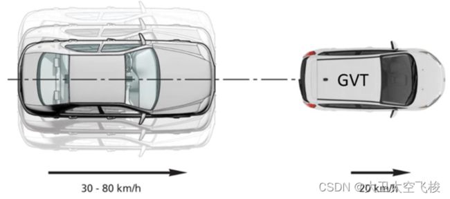
4.1.2 Car-to-Car Rear moving
4.1.3 Car-to-Car Rear braking
4.1.4 CCFtap
4.1.5 CCCscp
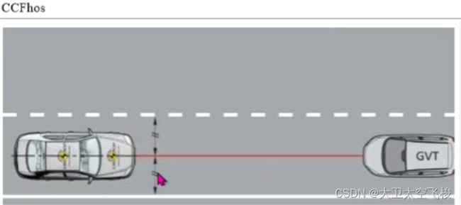
4.1.6 CCFhos
4.1.7 CCFhol
4.2 Car-to-Bicyclist Scenarios C2B 场景
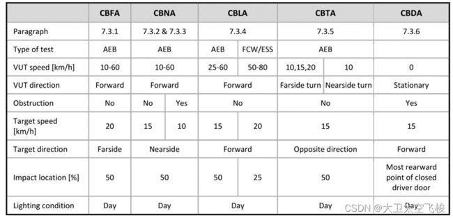
4.2.1 Car-to-Bicyclist Farside Adult
CBFA scenario, Bicyclist from Farside
4.2.2 Car-to-Bicyclist Nearside Adult
CBNA scenario, Bicyclist from Nearside
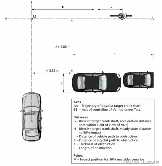
4.2.3 Car-to-Bicyclist Nearside Adult Obstructed
CBNAO scenario, Bicyclist from Nearside (obstructed)
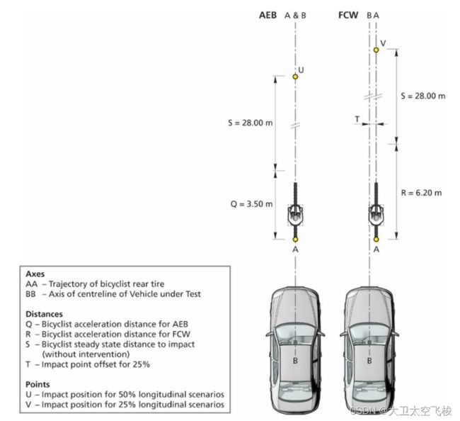
4.2.4 Car-to-Bicyclist Longitudinal Adult
CBLA scenarios, Longitudinal Bicyclist (AEB left & FCW right)
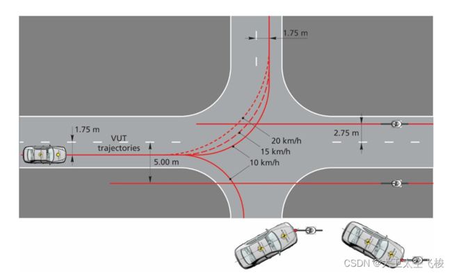
4.2.5 Car-to-Bicyclist Turning Adult
CBTA scenarios, Turning cycling Adult
4.2.6 Car-to-Bicyclist Dooring
CBDA scenarios, Dooring cycling Adult
4.3 Car-to-Pedestrian Scenarios C2P 场景
4.3.1 Car-to-Pedestrian Farside Adult
CPFA50
4.3.2 Car-to-Pedestrian Nearside Adult
CPNA 25/75
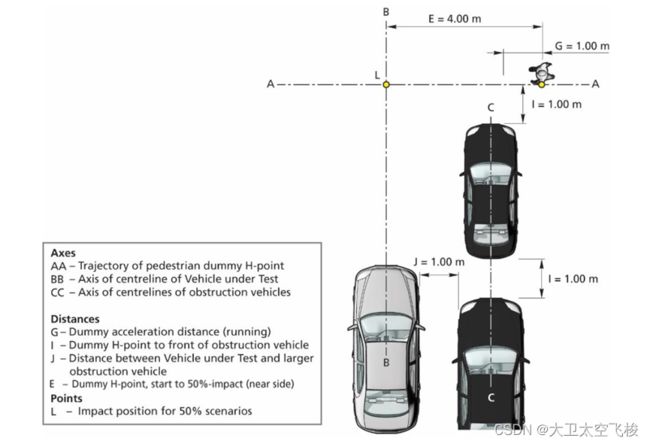
4.3.3 Car-to-Pedestrian Nearside Child Obstructed
CPNCO 50 ,又名鬼探头
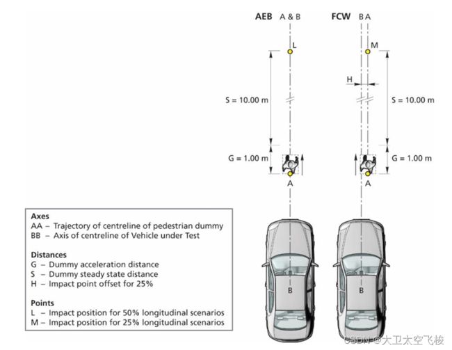
4.3.4 Car-to-Pedestrian Longitudinal Adul
CPLA
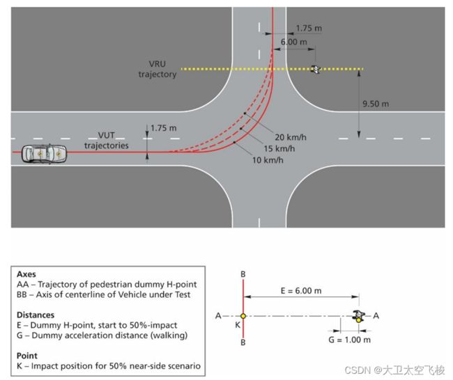
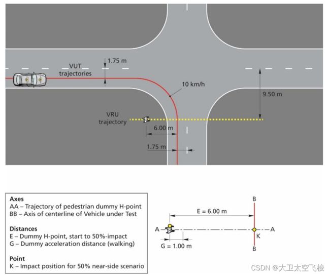
4.3.5 Car-to-Pedestrian Turning Adult
情境1:
CPTA scenario – VUT left turn, pedestrian crossing from farside
情境2:
CPTA scenario – VUT left turn, pedestrian crossing from nearside
情境3:
CPTA scenario – VUT right turn, pedestrian crossing from farside
情境4:
CPTA scenario – VUT right turn, pedestrian crossing from nearside
4.3.6 Car-to-Pedestrian Reverse Adult/Child
CPRA/CPRC scenario, Pedestrian from Nearside (left) and Stationary (right)
4.4 Car-to-Motorcyclis C2M 场景
4.4.1 Car-to-Motorcyclist Rear stationary
CMRs scenario
4.4.2 Car-to-Motorcyclist Rear braking
CMRb scenario
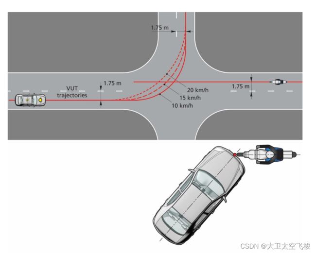
4.4.3 Car-to-Motorcyclist Front turn across path
CMFtap scenario VUT and EMT paths
4.4.4 Car-to-Motorcycle LSS Test Scenarios
略
4.4.5 Car-to-Motorcyclist oncoming
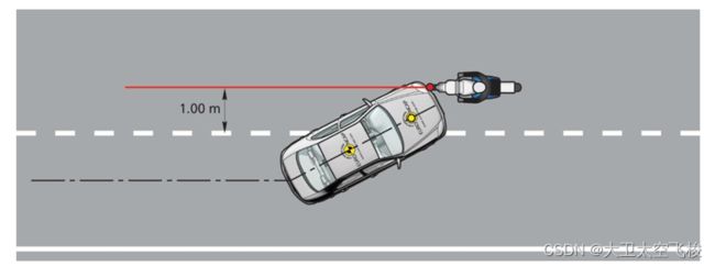
4.4.6 Car-to-Motorcyclist overtaking
4.5 非法规场景
法规场景的扩展
交叉场景
传感器受限场景
被遮挡
传感器故障
误制动
停车场
小区
隧道
桥梁
弯道
铁道
铁板
5. 功能描述
AEB系统包括以下功能:
FCW
Brake Prefill
Brake Jerk
AEB
DBS IBA
车身控制
6. AEB 系统组成
6.1 AEB 系统组成架构
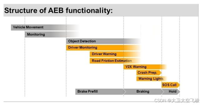
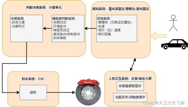
AEB 系统由四部分组成:感知系统,判断决策系统,刹车系统及人机交互系统 HMI。
感知系统负责对车辆周边环境进行探测感知,获取周围有效目标的类型属性及运动属性,一般由摄像头,毫米波雷达和/或激光雷达构成。
判断决策系统负责根据感知系统提供的潜在目标,结合本车运动属性进行分析判断,挑选出最具有威胁度的目标。此系统需要根据自身的运动状态,同时判断出自车与潜在目标的行进轨迹,并进一步判断是否两者之间存在合理的 TTC(Time To Collision)。但仅有 TTC 是不足够的,该系统还需要判断两者在此 TTC 时间上是否存在空间重叠(即碰撞)的可能性。刹车系统负责对接收到的减速度命令进行实际实施,并且也负责对部分功能安全需求进行实施。
而人机交互系统不仅提供了 AEB 功能及其可调节项的调节界面,也是进行 AEB 相关报警信息显示及声光报警的主要系统。
6.2 感知设备
详细内容参见系统需求、软件需求设计章节
6.3 控制设备
详细内容参见系统需求、软件需求设计章节
6.4 网关设备
第一种情形是当前主流车型正在使用的网关方式。
第二种情形是正在更新域控制器模式。
第三种情形未来发展趋势。
6.5 执行设备
详细内容参见系统需求、软件需求设计章节
6.5.1 动力
略
6.5.2 车身
BCM
6.5.3 底盘
Brake:主要包括ESC、EPB、Ibooster
转向系统
6.6 人机交互HMI
详细内容参见系统需求、软件需求设计章节
7. 名词释义
Autonomous Emergency Braking (AEB) – braking that is applied automatically by the vehicle in response to the detection of a likely collision to reduce the vehicle speed and potentially avoid the collision.
Forward Collision Warning (FCW) – an audio-visual warning that is provided automatically by the vehicle in response the detection of a likely collision to alert the driver.
Dynamic Brake Support (DBS) – a system that further amplifies the driver braking demand in response to the detection of a likely collision to achieve a greater deceleration than would otherwise be achieved for the braking demand in normal driving conditions.
Autonomous Emergency Steering (AES) –steering that is applied automatically by the vehicle in response to the detection of a likely collision to steer the vehicle around the vehicle in front to avoid the collision.
Emergency Steering Support (ESS) – a system that supports the driver steering input in response to the detection of a likely collision to alter the vehicle path and potentially avoid a collision.
Car-to-Bicyclist Dooring Adult (CBDA) – a collision between the vehicle’s door and a bicyclist traveling alongside the parked vehicle.
Car-to-Pedestrian Farside Adult 50% (CPFA-50) – a collision in which a vehicle travelsforwards towards an adult pedestrian crossing its path running from the farside and the frontal structure of the vehicle strikes the pedestrian at 50% of the vehicle's width when no braking action is applied.
Car-to-Pedestrian Nearside Adult 25% (CPNA-25) – a collision in which a vehicle travels forwards towards an adult pedestrian crossing its path walking from the nearside and the frontal structure of the vehicle strikes the pedestrian at 25% of the vehicle’s width when no braking action is applied.
Car-to-Pedestrian Adult 75% (CPNA-75) – a collision in which a vehicle travels forwards towards an adult pedestrian crossing its path walking from the nearside and the frontal structure of the vehicle strikes the pedestrian at 75% of the vehicle’s width when no braking action is applied.
Car-to-Pedestrian Nearside Child Obstructed 50% (CPNCO-50) – a collision in which a vehicle travels forwards towards a child pedestrian crossing its path running from behind and obstruction from the nearside and the frontal structure of the vehicle strikes the pedestrian at 50% of the vehicle's width when no braking action is applied.
Car-to-Pedestrian Longitudinal Adult 25% (CPLA-25) – a collision in which a vehicle travels forwards towards an adult pedestrian walking in the same direction in front of the vehicle where the vehicle strikes the pedestrian at 25% of the vehicle’s width when no braking action is applied, or an evasive steering action is initiated after an FCW.
Car-to-Pedestrian Longitudinal Adult 50% (CPLA-50) – a collision in which a vehicle travels forwards towards an adult pedestrian walking in the same direction in front of the vehicle where the vehicle strikes the pedestrian at 50% of the vehicle’s width when no braking action is applied.
Car-to-Pedestrian Turning Adult 50% (CPTA-50) – a collision in which a vehicle turns towards an adult pedestrian crossing its path, walking across a junction (in either the same and opposite direction as the VUT, before the VUT made the turn) and the frontal structure of the vehicle strikes the pedestrian at 50% of the vehicle's width when no braking action is applied.
Car-to-Pedestrian Reverse Adult/Child moving 50% (CPRA/Cm-50) – a collision in which a vehicle travels rearwards towards an adult or child pedestrian crossing its path walking from the nearside and the rear structure of the vehicle strikes the pedestrian at 50% of the vehicle’s width when no braking action is applied.
Car-to-Pedestrian Reverse Adult/Child stationary (CPRA/Cs) – a collision in which a vehicle travels rearwards towards an adult or child pedestrian standing still and the rear structure of the vehicle strikes the pedestrian at 25, 50 or 75% of the vehicle’s width when no braking action is applied.
Car-to-Bicyclist Nearside Adult 50% (CBNA-50) – a collision in which a vehicle travels forwards towards a bicyclist crossing its path cycling from the nearside and the frontal structure of the vehicle strikes the bicyclist when no braking action is applied.
Car-to-Bicyclist Nearside Adult Obstructed 50% (CBNAO-50) – a collision in which a vehicle travels forwards towards a bicyclist crossing its path cycling from the nearside from behind an obstruction and the frontal structure of the vehicle strikes the bicyclist at 50% of the vehicle's width when no braking action is applied.
Car-to-Bicyclist Farside Adult 50% (CBFA-50) – a collision in which a vehicle travels forwards towards a bicyclist crossing its path cycling from the farside and the frontal structure of the vehicle strikes the bicyclist at 50% of the vehicle's width when no braking action is applied.
Car-to-Bicyclist Longitudinal Adult 25% (CBLA-25) – a collision in which a vehicle travels forwards towards a bicyclist cycling in the same direction in front of the vehicle where the vehicle would strike the cyclist at 25% of the vehicle’s width when no braking action is applied or an evasive steering action is initiated after an FCW.
Car-to-Bicyclist Longitudinal Adult 50% (CBLA-50) – a collision in which a vehicle travels forwards towards a bicyclist cycling in the same direction in front of the vehicle where the vehicle would strike the cyclist at 50% of the vehicle’s width when no braking action is applied.
Car-to-Bicyclist Turning Adult 50% (CBTA-50) – a collision in which a vehicle turns towards a bicyclist crossing its path, walking across a junction (in either the same and opposite direction as the VUT, before the VUT made the turn) and the frontal structure of the vehicle strikes the pedestrian at 50% of the vehicle's width when no braking action is applied.
Car-to-Motorcyclist Rear Stationary (CMRs) – a collision in which a vehicle travels forwards towards a motorcyclist and the front structure of the vehicle strikes the rear of the motorcycle.
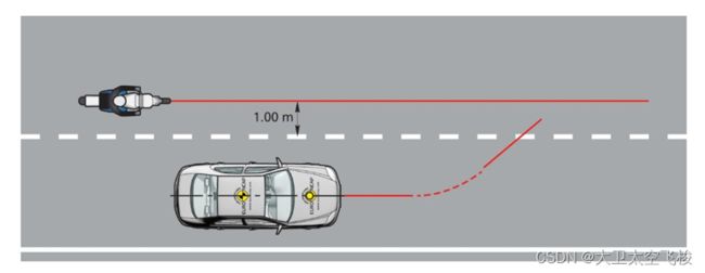
Car-to-Motorcyclist Rear Braking (CMRb) – a collision in which a vehicle travels forwards towards a motorcyclist that is travelling at constant speed and then decelerates, and the frontal structure of the vehicle strikes the rear of the motorcycle.
Car-to-Motorcyclist Front Turn Across Path (CMFtap) – a collision in which a vehicle turns across the path of an oncoming motorcyclist travelling at a constant speed, and the frontal structure of the vehicle strikes the front of the motorcycle.
Car-to-Motorcyclist Oncoming (CMoncoming) – a collision in which a vehicle drifts out of lane and into the path of a motorcyclist travelling in the opposite direction in the adjacent lane.
Car-to-Motorcyclist Overtaking (CMovertaking) – a collision in which a vehicle drifts out of lane and into the path of a motorcyclist travelling in the same direction in the adjacent lane.
Car-to-Car Rear stationary (CCRs) – a collision in which a vehicle travels forwards towards another stationary vehicle and the frontal structure of the vehicle strikes the rear structure of the other.
Car-to-Car Rear moving (CCRm) – a collision in which a vehicle travels forwards towards another vehicle that is travelling at constant speed and the frontal structure of the vehicle strikes the rear structure of the other.
Car-to-Car Rear braking (CCRb) – a collision in which a vehicle travels forwards towards another vehicle that is travelling at constant speed and then decelerates, and the frontal structure of the vehicle strikes the rear structure of the other.
Car-to-Car Front Turn-Across-Path (CCFtap) – a collision in which a vehicle turns across the path of an oncoming vehicle travelling at constant speed, and the frontal structure of the vehicle strikes the front structure of the other.
Time To Collision (TTC) – means the remaining time before the VUT strikes the GVT,assuming that the VUT and GVT would continue to travel with the speed it is travelling.
Distance To Lane Edge (DTLE) – means the remaining lateral distance (perpendicular to the Lane Edge) between the Lane Edge and most outer edge of the tyre, before the VUT crosses Lane Edge, assuming that the VUT would continue to travel with the same lateral velocity towards it.
Vehicle under test (VUT) – means the vehicle tested according to this protocol with a pre-crash collision mitigation or avoidance system on board.
Global Vehicle Target (GVT) – means the vehicle target used in this protocol as defined in TB025 - Global Vehicle Target specification for Euro NCAP v1.0.
Vrel_test – means the relative speed between the VUT and the EVT by subtracting the velocity of the EVT from that of the VUT at the start of test.
Vimpact – means the speed at which the VUT hits the EVT.
Vrel_impact – means the relative speed at which the VUT hits the EVT by subtracting the velocity of the EVT from Vimpact at the time of collision.
……
8. 参考文献
以下是关于 Time-to-Collision (TTC) 和 TTC AEB 算法原理的一些推荐文献:
1. "A Review of Time-to-Collision Estimation Techniques for Advanced Driver Assistance Systems" (IEEE Xplore) - 该文献提供了对 TTC 估计技术的综述,包括基于视觉和雷达数据的方法。该论文通过实验验证了最新的 TTC 算法的性能。可通过 IEEE Xplore 网站访问。
2. "Braking Time-to-Collision Control for the Car-Following Scenario" (MDPI) - 该文献描述了一种基于 TTC 的汽车控制方法,旨在提高车辆的安全性和性能。该文献详细介绍了方法的设计和实现,并通过仿真实验进行了验证。可通过 MDPI 网站访问。
3. "Real-Time Implementation of TTC-Based AEB System for Electric Vehicles" (Springer) - 该文献介绍了一种基于 TTC 的自动紧急制动系统 AEB 的设计和实现,该系统适用于电动车辆。该文献详细说明了算法和控制策略,并验证其性能。可通过 Springer 网站访问。
4. "Development of TTC-Based AEB Algorithm for Autonomous Vehicles" (IEEE Xplore) - 该文献介绍了一种为自主驾驶汽车开发的 TTC AEB 算法,该算法基于车道标记和摄像机性能进行优化。本论文通过实验验证了该算法在不同场景下的性能。可通过 IEEE Xplore 网站访问。
以上这些文献介绍了基于 TTC 的汽车安全控制系统 AEB 的设计和实现,涵盖了视觉和雷达数据处理,控制策略和性能验证,可以作为学习和了解 TTC 和 TTC AEB 算法原理的参考文献。
本专题由深圳季连 Aigraphx 团队编写,旨在分享如何利用仿真软件快速开发 AEB 算法以产品化。文中涉及到的图片来自网络,如有侵权请联系,秒删。
深圳季连 Aigraphx 团队也在积极组织资源,使用大模型端到端来研究动态轨迹预测、规划与控制等,期待能够为交通运输领域的智能化发展提供良好的支持和推动。

