Linux内核V4L2架构
一.V4L2简介
V4L2是Video for linux2的简称,为linux中关于视频设备的内核驱动。是linux操作系统下一套用于采集图片、视频和音频数据的通用API接口,配合适当的视频采集设备和相应的驱动程序,可以实现图片、视频、音频等的采集。 V4L2支持三种方式来采集图像:内存映射方式(mmap)、直接读取方式(read)和用户指针;
二.V4L2框架
1.重要结构体
该结构体描述了视频采集设备的driver信息
01 struct v4l2_capability
02 {
03     __u8 driver[16];       // 驱动名字
04     __u8 card[32];         // 设备名字
05     __u8 bus_info[32];     // 设备在系统中的位置
06     __u32 version;         // 驱动版本号
07     __u32 capabilities;    // 设备支持的操作
08     __u32 reserved[4];     // 保留字段
09 };
该结构体描述当前camera(摄像机)支持的格式信息
01 struct v4l2_fmtdesc
02 {
03     __u32 index;               // 要查询的格式序号,应用程序设置
04     enum v4l2_buf_type type;   // 帧类型,应用程序设置
05     __u32 flags;               // 是否为压缩格式
06     __u8 description[32];      // 格式名称
07     __u32 pixelformat;         //所支持的格式
08     __u32 reserved[4];         // 保留
09 };
该结构体描述每帧图像的具体格式,包括帧类型以及图像的长、宽等信息
01 struct v4l2_format
02 {
03     enum v4l2_buf_type type;          // 帧类型,应用程序设置
04     union fmt
05     {
06         struct v4l2_pix_format pix;   // 视频设备使用
07         struct v4l2_window win;
08         struct v4l2_vbi_format vbi;
09         struct v4l2_sliced_vbi_format sliced;
10         __u8 raw_data[200];
11     };
12 };
该结构体描述申请的缓冲区的基本信息
01 struct v4l2_requestbuffers
02 {
03     __u32 count;                    // 缓冲区内缓冲帧的数目
04     enum v4l2_buf_type type;        // 缓冲帧数据格式
05     enum v4l2_memorymemory;         // 区别是内存映射还是用户指针方式
06     __u32 reserved[2];
07 };
该结构体表示一帧图像数据的基本信息,包含序号、缓冲帧长度和缓冲帧地址等信息
01 struct v4l2_buffer
02 {
03     __u32 index;                    //buffer 序号
04     enum v4l2_buf_type type;        //buffer 类型
05     __u32 byteused;                 //buffer 中已使用的字节数
06     __u32 flags;                    // 区分是MMAP 还是USERPTR
07     enum v4l2_field field;
08     struct timeval timestamp;       // 获取第一个字节时的系统时间
09     struct v4l2_timecode timecode;
10     __u32 sequence;                 // 队列中的序号
11     enum v4l2_memory memory;        //IO 方式,被应用程序设置
12     union m
13     {
14         __u32 offset;               // 缓冲帧地址,只对MMAP 有效
15         unsigned long userptr;
16     };
17     __u32 length;                   // 缓冲帧长度
18     __u32 input;
19     __u32 reserved;
20 };
2.v4l2的实现流程
1)Video设备又分为主设备和从设备对于Camera来说, 主设备: Camera Host控制器为主设备,负责图像数据的接收和传输, 从设备: 从设备为Camera Sensor,一般为I2C接口,可通过从设备控制Camera采集图像的行为,如图像的大小、图像的FPS等。V4L2的主设备号是81,次设备号范围0~255
2)这些次设备号又分为多类设备:
视频设备(次设备号范围0-63)
Radio(收音机)设备(次设备号范围64-127)
Teletext设备(次设备号范围192-223)
VBI设备(次设备号范围224-255)。
V4L2设备对应的设备节点有/dev/videoX、/dev/vbiX、/dev/radioX。
本文只讨论视频设备,视频设备对应的设备节点是/dev/videoX,视频设备以高频摄像头或Camera为输入源,Linux内核驱动该类设备,接收相应的视频信息并处理
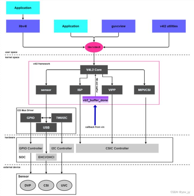
2.0v4l2的分层
user space: 应用程序主要通过libv4l库来操作摄像头 也可以基于字符设备/dev/videoX自己编写应用程序 guvcview:用于调试usb摄像头(还有个软件cheese也可以) v4l2 utilities: v4l2 的工具集(参考前面第3篇文章)
kernel space: sensor、ISP、VIPP、CSI、CCI都为从设备向上,提供dev/videoX节点, 从dphy物理层获取视频数据册通过vb2子模块 CCI :主要是通过GPIO(供电、片选)、I2C(下发配置命令给sensor)实现配置sensor EHCI/OHCI:USB类型摄像头
适用于收音机,视频编解码器,视频捕获器以及视频输出设备驱动;
hardware CSIC Controller:从dphy获取mipi协议帧 I2C Controller:与sensor的i2c block通信 GPIO Controller:sensor通常需要供电或者片选
Video Control:视频处理命令(分辨率协商,数据格式处理,buffer管理)
Runtime Handle:运行时管理(Pipeline 管理,系统资源管理,中断调度)
Event Process:事件管理(上层调用,中断等事件的接收和分发);
Config Handle:配置管理(硬件拓扑结构,模组自适应列表);
external device sensror:摄像头的接口主要有:USB,DVP.MIPI(CSI)
Camera Modules:模组驱动(图像传感器,对焦电机,闪光灯等)
Camera Interfac:接口驱动(MIPI, Sub-Lvds, HiSpi, Bt656, DC等)
Image Signal Processor:图像处理驱动(基本处理模块驱动,3A统计驱动)
Video Inout Post Processor:视频输入后处理(Scaler,OSD等)

2.1中重要的结构体、

1)v4l2_device主设备
    struct v4l2_device {
        struct device *dev;  // 父设备指针
    #if defined(CONFIG_MEDIA_CONTROLLER)  // 多媒体设备配置选项
        // 用于运行时数据流的管理,
        struct media_device *mdev;
    #endif
        // 注册的子设备的v4l2_subdev结构体都挂载此链表中
        struct list_head subdevs;
        // 同步用的自旋锁
        spinlock_t lock;
        // 独一无二的设备名称,默认使用driver name + bus ID
        char name[V4L2_DEVICE_NAME_SIZE];
        // 被一些子设备回调的通知函数,但这个设置与子设备相关。子设备支持的任何通知必须在
        // include/media/.h 中定义一个消息头。
        void (*notify)(struct v4l2_subdev *sd, unsigned int notification, void *arg);
        // 提供子设备(主要是video和ISP设备)在用户空间的特效操作接口,
        // 比如改变输出图像的亮度、对比度、饱和度等等
        struct v4l2_ctrl_handler *ctrl_handler;
        // 设备优先级状态
        struct v4l2_prio_state prio;
        /* BKL replacement mutex. Temporary solution only. */
        struct mutex ioctl_lock;
        // struct v4l2_device结构体的引用计数,等于0时才释放
        struct kref ref;
        // 引用计数ref为0时,调用release函数进行释放资源和清理工作
        void (*release)(struct v4l2_device *v4l2_dev);
    };
由上图可以知道v4l2_device是v4l2子系统的入口,管理v4l2zi系统的主设备和从设备。简单设备可以仅分配这个结构体,但在大多数情况下,都会将这个结构体嵌入到一个更大的结构体中以提供v4l2框架的功能,比如struct isp_device
2)video_device
struct video_device
{
const struct v4l2_file_operations *fops;
struct cdev *cdev; //vdev->cdev->ops = &v4l2_fops; 字符设备描述符
struct v4l2_device *v4l2_dev;
struct v4l2_ctrl_handler *ctrl_handler;
struct vb2_queue *queue; //q->ops = &dmarx_vb2_ops; buf操作真正驱动回调函数
…………
const struct v4l2_ioctl_ops *ioctl_ops;//vdev->ioctl_ops = &rkisp_dmarx_ioctl;
…………
};
V4L2子系统使用v4l2_device结构体管理设备,设备的具体操作方法根据设备类型决定,
前面说过管理的设备分为很多种,
若是视频设备,则需要注册video_device结构体,并提供相应的操作方法。
对于视频设备Camera而言,Camera控制器可以视为主设备,接在Camera控制器上的摄像头可以视为从设备。
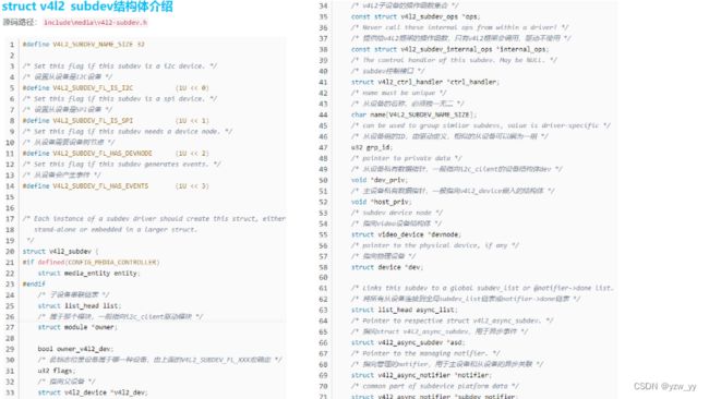
3) v4l2_subdev从设备
[include/media/v4l2-subdev.h]
#define V4L2_SUBDEV_FL_IS_I2C (1U << 0) // 从设备是I2C设备
#define V4L2_SUBDEV_FL_IS_SPI (1U << 1) // 从设备是SPI设备
#define V4L2_SUBDEV_FL_HAS_DEVNODE (1U << 2) // 从设备需要设备节点
#define V4L2_SUBDEV_FL_HAS_EVENTS (1U << 3) // 从设备会产生事件
struct v4l2_subdev {
#if defined(CONFIG_MEDIA_CONTROLLER) // 多媒体配置选项
struct media_entity entity;
#endif
struct list_head list; // 子设备串联链表
struct module *owner; // 属于那个模块,一般指向i2c_lient驱动模块
bool owner_v4l2_dev;
// 标志位,确定该设备属于那种设备,由V4L2_SUBDEV_FL_IS_XX宏确定
u32 flags;
// 指向主设备的v4l2_device结构体
struct v4l2_device *v4l2_dev;
// v4l2子设备的操作函数集合
const struct v4l2_subdev_ops *ops;
// 提供给v4l2框架的操作函数,只有v4l2框架会调用,驱动不使用
const struct v4l2_subdev_internal_ops *internal_ops;
// 从设备的控制接口
struct v4l2_ctrl_handler *ctrl_handler;
// 从设备的名称,必须独一无二
char name[V4L2_SUBDEV_NAME_SIZE];
// 从设备组的ID,由驱动定义,相似的从设备可以编为一组,
u32 grp_id;
// 从设备私有数据指针,一般指向i2c_client的设备结构体dev
void *dev_priv;
// 主设备私有数据指针,一般指向v4l2_device嵌入的结构体
void *host_priv;
// 指向video设备结构体
struct video_device *devnode;
// 指向物理设备
struct device *dev;
// 将所有从设备连接到全局subdev_list链表或notifier->done链表
struct list_head async_list;
// 指向struct v4l2_async_subdev,用于异步事件
struct v4l2_async_subdev *asd;
// 指向管理的notifier,用于主设备和从设备的异步关联
struct v4l2_async_notifier *notifier;
/* common part of subdevice platform data */
struct v4l2_subdev_platform_data *pdata;
};
// 提供给v4l2框架的操作函数,只有v4l2框架会调用,驱动不使用
struct v4l2_subdev_internal_ops {
// v4l2_subdev注册时回调此函数,使v4l2_dev指向主设备的v4l2_device结构体
int (*registered)(struct v4l2_subdev *sd);
// v4l2_subdev卸载时回调此函数
void (*unregistered)(struct v4l2_subdev *sd);
// 应用调用open打开从设备节点时调用此函数
int (*open)(struct v4l2_subdev *sd, struct v4l2_subdev_fh *fh);
// 应用调用close时调用此函数
int (*close)(struct v4l2_subdev *sd, struct v4l2_subdev_fh *fh);
};
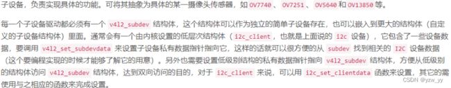
V4L2从设备使用struct v4l2_subdev结构体表示,该结构体用于对子设备进行抽象。
几乎所有的设备都有多个 IC 模块
它们可能是实体的(例如 USB 摄像头里面包含 ISP、sensor 等) 也可能是抽象的(如 USB 设备里面的抽象拓扑结构) 它们在 /dev 目录下面生成了多个设备节点,并且这些 IC 模块还创建了一些非 v4l2 设备:DVB、ALSA、FB、I2C 和输入设备。 通常情况下,这些IC模块通过一个或者多个 I2C 总线连接到主桥驱动上面,同时其它的总线仍然可用,这些 IC 就称为 ‘sub-devices’。
一个V4L2主设备可能对应多个V4L2从设备,所有主设备对应的从设备都挂到v4l2_device结构体的subdevs链表中。
对于视频设备,从设备就是摄像头,通常情况下是I2C设备,主设备可通过I2C总线控制从设备
例如控制摄像头的焦距、闪光灯等,同时使用 MIPI 或者 LVDS 等接口进行图像数据传输。
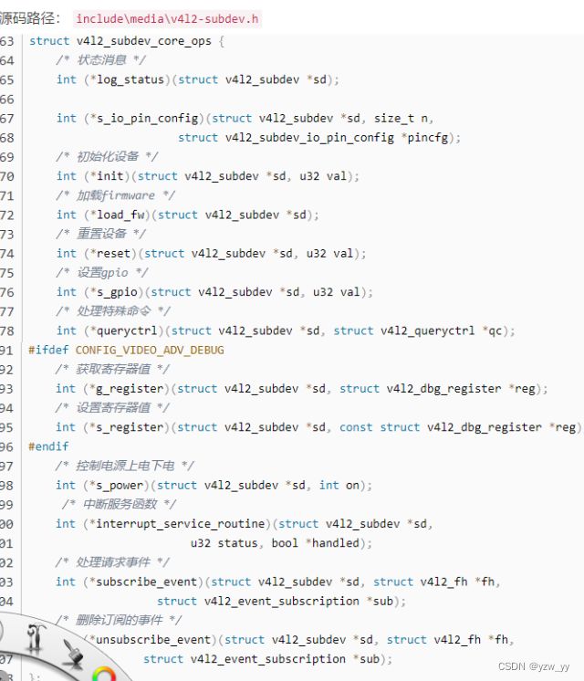
struct v4l2_subdev中包含的struct v4l2_subdev_ops是一个完备的操作函数集,用于对接各种不同的子设备,比如video、audio、sensor等;
4) v4l2_fh
文件访问控制
5)v4l2_ctrl_handler
控制模块,提供子设备(主要是 video 和 ISP 设备)在用户空间的特效操作接口
6)media_device
用于运行时数据流的管理,嵌入在 V4L2 device 内部
通过以上函数就完成了对摄像头v4l2框架的抽象
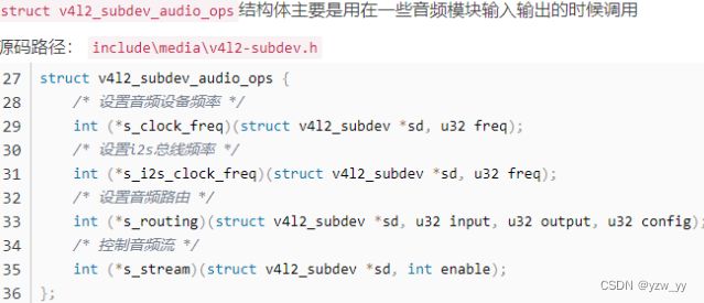
2.1V4L2子设备操作函数


三.设备树的修改
3.1基本知识
DCMI:DCMI是一个同步并行接口,能够从外部8bit、10bit、12bit或14bit的CMOS摄像头接收高速数据流,支持不同的数据格式:YCbCr4:2:2/RGB565渐进式视频和压缩数据(JPEG)

数据接收时序
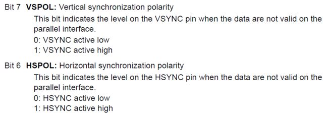
在DCMI中数据和同步时钟信号都是由摄像头模块提供的,在PIXCLK的上升沿或者下降沿采集数据, 时钟沿极性可以通过修改控制寄存器CR.PCKPOL位指定。而VSYNC称为帧同步信号,它指示了一帧数据的开始和结束; HSYNC称为行同步信号,指示了一帧图像中每一行数据的开始和结束,在JPEG模式下则用于指示可用数据。
上图2是一个接收数据时序的示意图,图中在PIXCLK的下降沿获取数据,HSYNC和VSYNC的有效状态为1。 (按:看图中的状态应该是在HSYNC和VSYNC为低电平的时候有效,这里却说1是有效状态。查看DCMI的控制寄存器CR的位定义, 文档中对于这两个信号的极性做了如下图的描述。所以,个人猜测HSYNC和VSYNC指示的是无效的数据状态。)

在DCMI中支持8位、10位、12位、14位的数据总线,我们可以通过控制寄存器CR的EDM位具体声明。 这些数据线总是以最低位(LSB)的形式接入DCMI的,比如说8位的线宽, 接入DCMI的数据线是DCMI_DR[0:7],10位则是DCMI_DR[0:9]。在DCMI中总是将接收到的数据拼接为一个32位的数据后,触发DMA请求。
对于8位的数据线宽,捕获一个32位数据需要4个像素时钟周期(PIXCLK),第一个字节放在LSB的位置上,第四个字节放在MSB上。 对于10位及以上的数据线宽,只需要2个像素时钟周期就可以产生一个32位数据,第一个周期采集的数据放在低16位的LSB上, 低16位的高位部分用0补齐;第二个周期则放在高16位的LSB上,高位用0补齐。
DCMI模块除了支持HSYNC和VSYNC这样的硬件时钟同步的方式外,还支持内嵌码的形式同步数据。 所谓的内嵌码是指在一帧图像中使用特定数字标着着一帧图像或者一行数据的开始和结束。这些特定的数字则不能够作为图像的数据内容使用, 通常是0xFF和0x00。这种内嵌码的工作方式支持8位线宽的摄像头,在DCMI中采用的0xFF0000XY的形式定义同步码的, XY的数据内容可以通过寄存器ESCR指定。详细参见官方手册。

由此可知,我们应去找dcmi接口。
3.2设备树
-
DCMI设备树节点
查找dcmi,内核中ST对STM32MP15x系列芯片的设备树资源了做了定义
arch/arm/boot/dts/stm32mp151.dtsi
dcmi: dcmi@4c006000 {
                        compatible = "st,stm32-dcmi";
                        reg = <0x4c006000 0x400>;
                        interrupts = ;
                        resets = <&rcc CAMITF_R>;
                        clocks = <&rcc DCMI>;
                        clock-names = "mclk";
                        dmas = <&dmamux1 75 0x400 0xe0000001>;
                        dma-names = "tx";
                        status = "disabled";
                };
当然这是远远不够的我们要自己添加一下dcmi节点所以我们到devicetree/bindings下搜索dcmi。
STMicroelectronics STM32 Digital Camera Memory Interface (DCMI)

Required properties:
- compatible: "st,stm32-dcmi"
- reg: physical base address and length of the registers set for the device
- interrupts: should contain IRQ line for the DCMI
- resets: reference to a reset controller,
          see Documentation/devicetree/bindings/reset/st,stm32-rcc.txt
- clocks: list of clock specifiers, corresponding to entries in
          the clock-names property
- clock-names: must contain "mclk", which is the DCMI peripherial clock
- pinctrl: the pincontrol settings to configure muxing properly
           for pins that connect to DCMI device.
           See Documentation/devicetree/bindings/pinctrl/st,stm32-pinctrl.yaml.
- dmas: phandle to DMA controller node,
        see Documentation/devicetree/bindings/dma/stm32-dma.txt
- dma-names: must contain "tx", which is the transmit channel from DCMI to DMA

DCMI supports a single port node with parallel bus. It should contain one
'port' child node with child 'endpoint' node. Please refer to the bindings
defined in Documentation/devicetree/bindings/media/video-interfaces.txt.

Example:
        dcmi: dcmi@50050000 {
                compatible = "st,stm32-dcmi";
                reg = <0x50050000 0x400>;
                interrupts = <78>;
                resets = <&rcc STM32F4_AHB2_RESET(DCMI)>;
                clocks = <&rcc 0 STM32F4_AHB2_CLOCK(DCMI)>;
                clock-names = "mclk";
                pinctrl-names = "default";
                pinctrl-0 = <&dcmi_pins>;
                dmas = <&dma2 1 1 0x414 0x3>;
                dma-names = "tx";
                port {
                        dcmi_0: endpoint {
                                remote-endpoint = <...>;
                                bus-width = <8>;
                                hsync-active = <0>;
                                vsync-active = <0>;
                                pclk-sample = <1>;
                        };
                };
        };
通过以上文件我们知道了要添加port和endpoint结点既然要添加节点我们就要去看一下,pinctrl文件里看一下引脚和我们所用是否一致,由于stm32mp15-pinctrl.dtsi中对于DCMI管脚的定义与FS-MP1A实际使用管脚一致,所以无需修改。我们只要添加一下节点即可。
&dcmi {
        status = "okay";
        pinctrl-names = "default", "sleep";
        pinctrl-0 = <&dcmi_pins_a>;
        pinctrl-1 = <&dcmi_sleep_pins_a>;

        port {
                dcmi_0: endpoint {
                        remote-endpoint = <&ov5640_0>;
                        bus-width = <8>;
                        hsync-active = <0>;
                        vsync-active = <0>;
                        pclk-sample = <1>;
                        pclk-max-frequency = <77000000>;
                };
        };
};
CMOS Camera设备树节点
这里以0v5640举例子同样我们到devicetree/bindings下搜索ov5640。进到media/i2c/ov5640.txt去看
* Omnivision OV5640 MIPI CSI-2 / parallel sensor

Required Properties:
- compatible: should be "ovti,ov5640"
- clocks: reference to the xclk input clock.
- clock-names: should be "xclk".
- DOVDD-supply: Digital I/O voltage supply, 1.8 volts
- AVDD-supply: Analog voltage supply, 2.8 volts
- DVDD-supply: Digital core voltage supply, 1.5 volts

Optional Properties:
- reset-gpios: reference to the GPIO connected to the reset pin, if any.
               This is an active low signal to the OV5640.
- powerdown-gpios: reference to the GPIO connected to the powerdown pin,
                   if any. This is an active high signal to the OV5640.
- rotation: as defined in
            Documentation/devicetree/bindings/media/video-interfaces.txt,
            valid values are 0 (sensor mounted upright) and 180 (sensor
            mounted upside down).

The device node must contain one 'port' child node for its digital output
video port, in accordance with the video interface bindings defined in
Documentation/devicetree/bindings/media/video-interfaces.txt.

OV5640 can be connected to a MIPI CSI-2 bus or a parallel bus endpoint.

Endpoint node required properties for CSI-2 connection are:
- remote-endpoint: a phandle to the bus receiver's endpoint node.
- clock-lanes: should be set to <0> (clock lane on hardware lane 0)
- data-lanes: should be set to <1> or <1 2> (one or two CSI-2 lanes supported)

Endpoint node required properties for parallel connection are:
- remote-endpoint: a phandle to the bus receiver's endpoint node.
- bus-width: shall be set to <8> for 8 bits parallel bus
             or <10> for 10 bits parallel bus
- data-shift: shall be set to <2> for 8 bits parallel bus
              (lines 9:2 are used) or <0> for 10 bits parallel bus
- hsync-active: active state of the HSYNC signal, 0/1 for LOW/HIGH respectively.
- vsync-active: active state of the VSYNC signal, 0/1 for LOW/HIGH respectively.
- pclk-sample: sample data on rising (1) or falling (0) edge of the pixel clock
               signal.

Examples:

&i2c1 {
        ov5640: camera@3c {
                compatible = "ovti,ov5640";
                pinctrl-names = "default";
                pinctrl-0 = <&pinctrl_ov5640>;
                reg = <0x3c>;
                clocks = <&clks IMX6QDL_CLK_CKO>;
                clock-names = "xclk";
                DOVDD-supply = <&vgen4_reg>; /* 1.8v */
                AVDD-supply = <&vgen3_reg>;  /* 2.8v */
                DVDD-supply = <&vgen2_reg>;  /* 1.5v */
                powerdown-gpios = <&gpio1 19 GPIO_ACTIVE_HIGH>;
                reset-gpios = <&gpio1 20 GPIO_ACTIVE_LOW>;
                rotation = <180>;

                port {
                        /* MIPI CSI-2 bus endpoint */
                        ov5640_to_mipi_csi2: endpoint {
                                remote-endpoint = <&mipi_csi2_from_ov5640>;
                                clock-lanes = <0>;
                                data-lanes = <1 2>;
                        };
                };
        };
};
&i2c1 {
        ov5640: camera@3c {
                compatible = "ovti,ov5640";
                pinctrl-names = "default";
                pinctrl-0 = <&pinctrl_ov5640>;
                reg = <0x3c>;
                clocks = <&clk_ext_camera>;
                clock-names = "xclk";

                port {
                        /* Parallel bus endpoint */
                        ov5640_to_parallel: endpoint {
                                remote-endpoint = <¶llel_from_ov5640>;
                                bus-width = <8>;
                                data-shift = <2>; /* lines 9:2 are used */
                                hsync-active = <0>;
                                vsync-active = <0>;
                                pclk-sample = <1>;
                        };
                };
        };
};
通过上文知道了我们要怎么添加设备树
ov5640: camera@3c {
    compatible = "ovti,ov5640";
    reg = <0x3c>;
    clocks = <&clk_ext_camera>;
    clock-names = "xclk";
    DOVDD-supply = <&v2v8>;
    powerdown-gpios = <&gpioa 4 (GPIO_ACTIVE_HIGH | GPIO_PUSH_PULL)>;
    reset-gpios = <&gpioa 3 (GPIO_ACTIVE_LOW | GPIO_PUSH_PULL)>;
    rotation = <180>;
    status = "okay";
    port {
        ov5640_0: endpoint {
            remote-endpoint = <&dcmi_0>;
            bus-width = <8>;
            data-shift = <2>; /* lines 9:2 are used */
            hsync-active = <0>;
            vsync-active = <0>;
            pclk-sample = <1>;
            pclk-max-frequency = <77000000>;
        };
    };
};
由于我们这里用了2.8V电源和24M时钟所以我们去添加这两个
同样我们不知道怎么写去devicetree/bindings/regulator/st,stpmic1-regulator.txt文件下参考。之后补充
    v2v8: regulator-2p8v {
            compatible = "regulator-fixed";
            regulator-name = "v2v8";
            regulator-min-microvolt = <2800000>;
            regulator-max-microvolt = <2800000>;
            regulator-always-on;
            regulator-boot-on;
    };
    clocks {
            clk_ext_camera: clk-ext-camera {
                    #clock-cells = <0>;
                    compatible = "fixed-clock";
                    clock-frequency = <24000000>;
            };
    };
3.3编译内核
linux@ubuntu:$ make menuconfig
Device Drivers --->
  <*> Multimedia support --->
      [*] V4L platform devices --->
          <*> STM32 Digital Camera Memory Interface (DCMI) support
      I2C Encoders, decoders, sensors and other helper chips --->
          <*> OmniVision OV5640 sensor support
四.用ffmpeg测试
4.1添加ffmpeg
利用buildroot-2021.02.1添加ffmpeg

选中alsa-utils和ffmpeg之后进入ffmpeg

选中自己需要用到的库。之后sudo make,考备至开发板。
4.2视频测试
执行以下命令测试录制视频
ffmpeg -f v4l2 -framerate 10 -i /dev/video1 -q 10 my.mp4
4.3搭建nginx-rtmp服务器进行推流拉流测试
安装以下依赖

创建文件夹存放nginx
mkdir rtmp

cd rtmp

wget http://nginx.org/download/nginx-1.13.3.tar.gz
去github下载nginx-rtmp模块
git clone https://github.com/arut/nginx-rtmp-module.git

tar -zxvf nginx-1.13.3.tar.gz

cd nginx-1.13.3

./configure --add-module=../nginx-rtmp-module

make

make install
由于版本nginx版本不同,这里不一定能编译通过。
没报错的话,会有如下目录
/usr/local/nginx
cd /usr/local/nginx

cd sbin
启动nginx ./nginx 启动niginx时也可能出现错误,如下:
asdf@ubuntu:/usr/local/nginx/sbin$ ./nginx
nginx: [alert] could not open error log file: open() "/usr/local/nginx/logs/error.log" failed (13: Permission denied)
2021/07/07 07:39:22 [emerg] 23751#0: mkdir() "/usr/local/nginx/client_body_temp" failed (13: Permission denied)
此时需要修改权限
sudo chown root nginx sudo chmod u+s nginx
查看进程
ps -ef|grep nginx
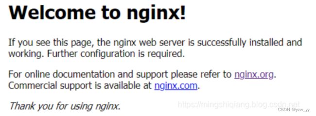
ifconfig 查看ip,浏览器访问ip,看到下图, 说明nginx安装ok.
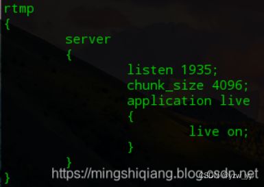
注意:这是动态ip, 每次开机启动都不同,如果推流失败可能是ip变动了。 配置rtmp服务 配置文件修改, cd到nginx的conf目录 vim nginx.conf 添加如下内容
重启nginx pkill nginx
重启./nginx
推本地流测试 ffmpeg -re -i 1.mp4 -f flv rtmp://192.168.126.132/live
实时推流测试
ffmpeg -f v4l2 -framerate 15 -i /dev/video0 -q 15 -f flv rtmp://192.168.126.132/live
下载VLC软件
VLC播放测试