2021-08-21Verilog三段式状态机的写法,标准示例和仿真。
Verilog三段式状态机的写法,标准示例和仿真。
第一段:同步状态转移。第一个always块格式化描述次态寄存器迁移到现态寄存器。
第二段:当前状态判断接下来的状态。组合逻辑always模块,描述状态转移条件判断用current_state
第三段:次态描述输出。同步时序always模块,描述次态寄存器输出(有误,见下一篇文章)
注意:
三段式并不是一定要写为3个always块,如果状态机更复杂,就不止3段了。
- 三段always模块中,第一个和第三个always模块是同步时序always模块,用非阻塞赋值(“ <= ”);第二个always模块是组合逻辑always模块,用阻塞赋值(“ = ”)。
- 第二部分为组合逻辑always模块,为了抑制warning信息,对于always的敏感列表建议采用always@(*)的方式。
- 第二部分,组合逻辑always模块,里面判断条件一定要包含所有情况!可以用else保证包含完全。
- 第二部分,组合逻辑电平要维持超过一个clock,仿真时注意。
- 需要注意:第二部分case中的条件应该为当前态(current_state)。
- 第三部分case中的条件应该为次态(next_state)。
- 编码原则,binary和gray-code适用于触发器资源较少,组合电路资源丰富的情况(CPLD),对于FPGA,适用one-hot code。这样不但充分利用FPGA丰富的触发器资源,还因为只需比较一个bit,速度快,组合电路简单。
示例1. 状态转移图:
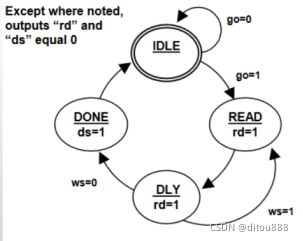
(1)fsm.v文件:
module fsm(//go,ws,clk,rst_n,rd,ds);
input go,
input ws,
input clk,
input rst_n,
output reg rd,
output reg ds,
output reg [1:0] current_state,
output reg [1:0] next_state,
output reg [3:0] led
);
//reg rd,ds;
parameter [1:0] IDLE = 2’b00;
parameter [1:0] READ = 2’b01;
parameter [1:0] DLY = 2’b10;
parameter [1:0] DONE = 2’b11;
//reg [1:0] current_state,next_state;
//next state logic
always @(posedge clk or negedge rst_n)begin
if(!rst_n) current_state <= IDLE;
else current_state <= next_state;//
end
//state register
always @(current_state or go or ws)begin
next_state = 2’bx;
case(current_state)
IDLE : if(go) next_state = READ;
else next_state = IDLE;
READ : next_state = DLY;
DLY : if(ws) next_state = READ;
else next_state = DONE;
DONE : next_state = IDLE;
endcase
end
//Output logic
always @(posedge clk or negedge rst_n)begin
if(!rst_n)begin
rd <= 1’b0;
ds <= 1’b0;
end
else begin
rd <= 1’b0;
ds <= 1’b0;
led <= 4’b0000;
case(next_state)//注意是next_state.
IDLE: if(go) begin rd <= 1’b1; led <= 4’b0001; end
READ: begin rd <= 1’b1; led <= 4’b0010; end
DLY: if(ws) begin rd <= 1’b1; led <= 4’b0100; end
else begin ds <= 1’b1; led <= 4’b1000; end
DONE: begin ds <= 1’b1; led <= 4’b1000; end
endcase
end
end
Endmodule
(2)fsm_test.v文件:
`timescale 1ns/1ps
module fsm_test();
reg clk;
reg rst_n;
reg go;
reg ws;
wire rd;
wire ds;
wire [3:0] led;
wire [1:0] current_state;
wire [1:0] next_state;
fsm u1(
.go(go),
.ws(ws),
.clk(clk),
.rst_n(rst_n),
.rd(rd),
.ds(ds),
.current_state(current_state),
.next_state(next_state),
.led(led)
);
initial begin
clk =1’b0;
rst_n = 1’b1;
#50 rst_n =1’b0;
#50 rst_n =1’b1;
go = 1’b0;
ws = 1’b0;
#100 go = 1’b1;
#2000 $stop;//仿真2000ns后停止。
end
always #25 clk = ~clk;
Endmodule
仿真波形如下:
状态和输出对得上。需要注意第三个always块里的state用的是next_state.
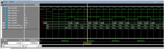
原问题:当第三段使用current_state判断时,状态和输出对不上。改为next_state正常。
仿真发现状态跳转不对:
