Introduction to 555 timer 【数字电路】
Introduction to 555 timer
555 定时器 wiki
话说明天考数电,今天晚上最后时刻要搞定 555 timer啊!哈哈
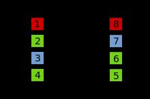
各个引脚的介绍
| Pin | Name | Purpose |
|---|---|---|
| 1 | GND | Ground reference voltage, low level (0 V) |
| 2 | TRIG | The OUT pin goes high and a timing interval starts when this input falls below 1/2 of CTRL voltage (which is typically 1/3 of VCC, when CTRL is open). |
| 3 | OUT | This output is driven to approximately 1.7 V below +VCC or GND. |
| 4 | RESET | A timing interval may be reset by driving this input to GND, but the timing does not begin again until RESET rises above approximately 0.7 volts. Overrides TRIG which overrides THR. |
| 5 | CTRL | Provides "control" access to the internal voltage divider (by default, 2/3 VCC). |
| 6 | THR | The timing (OUT high) interval ends when the voltage at THR is greater than that at CTRL (2/3 VCC if CTRL is open). |
| 7 | DIS | Open collector output which may discharge a capacitor between intervals. In phase with output. |
| 8 | VCC | Positive supply voltage, which is usually between 3 and 15 V depending on the variation. |
经典到shi的555 timer。
有很多以“为什么”开头的问题,如果不知道实现细节是无法圆满回答的。So ..... 下面是555 timer的实现原理细节。
为什么是叫555呢?貌似没有准确的回答,是设计者叫的名字之后大家都跟着叫,不过我到书上有555 timer的实现的时候那三个电阻的值是取的三个5K,我估计八成是这个原因。。。用了三个5K的电阻。。。
沉下心来搞定这个实现原理,之后的应用的理解也就会变得游刃有余。
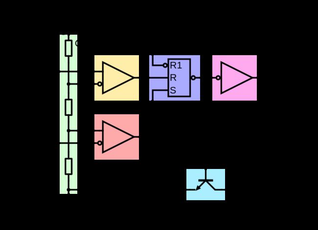
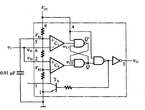
两个comparetor C1 C2 ,一个RS trigger,一个NPN的transistor,三个resistor,一个and not gate,一个 not gate。所有的器件。
根本的思想,我觉得还是结合两个比较器产生高输出电压,然后利用SR trigger去实现波形的输出发生。
三种经典工作模式
一般三种模式都有个共同点,就是把control引脚接一个10nF的电容,然后接地。
1. Monostable (单稳态 模式)
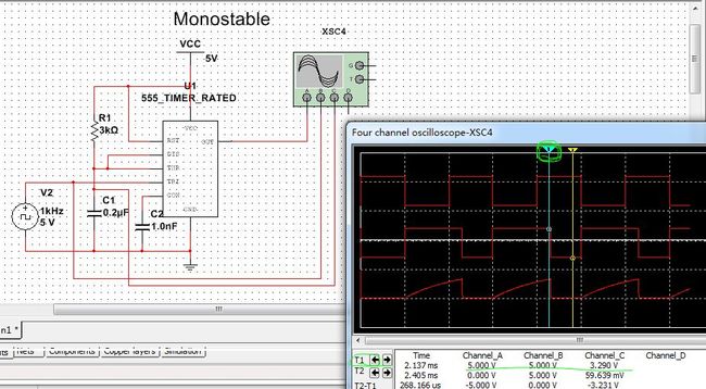
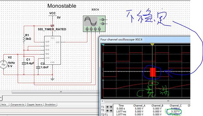
正确的555 timer工作在 monostable模式下的电路连线是这样的:把therashold端(Vi 1)和trigger (Vi 2)端连在一起,作为输入端。
输出周期脉冲的波形,高电平时长为 = 1.1*RC,这里我取值是R = 3K,C = 0.2uF,于是Tw 约等于760us
切记,不要让输出波形的下降沿处于输入波形的低电平段,这样将导致输出不稳定。例如:我把电容改到0.4uF,这里tw增大,并且电容充满电(2/3 Vcc)的时候,会有一段不稳定输出。一开始我始终不明白为什么会有不稳定的输出。后来明白了,特此提出。
不稳定的输出源于,这里Vi 1 是2/3 Vcc ,这与C1 的另外一个输入端Vco 电压几乎是一致的,造成Vc1的不稳定输出,而Vi2是低电平,于是Vc2输出了低电平,此时Vc2 电平,而Vc1是不稳定的,于是出现了输出的不稳定。选取恰当的RC的值,不要让输出波形的下降沿位于输入波形的低电平段即可!
2.bistable(schmitt trigger 模式)
感觉wiki的电路图错了,希望有人可以去改正一下,如果有兴趣可以和我讨论。Therashold 和 trigger端口应该连接在一起,接输入信号。
下面是我按照书上接的电路图。
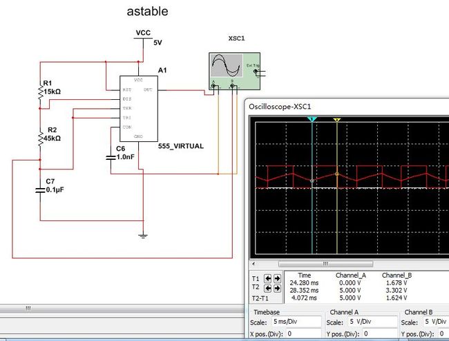
3.astable(多谐振荡器 模式)
差点被忽悠气昏过去。。。
结果老是不对。换一个555 timer的模型就好了。。。Multisim啊。。。
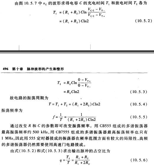
相关参数的计算:
