基于FPGA的CORDIC算法的实现(1)
CORDIC算法向量模式原理介绍及FPGA实现
- 参考文献
- 项目简述
- CORDIC算法向量模式原理
- CIRDIC算法向量模式推导步骤一
- CIRDIC算法向量模式推导步骤二
- CIRDIC算法向量模式推导步骤三
- CIRDIC算法向量模式推导步骤三
- MATLAB实现
- FPGA实现
- MATLAB测试代码
- 总结
参考文献
[1].liyuanbhu
[2].碎碎思
[3].电子发烧友(这门课里面的代码写的非常棒,建议有条件的同学可以与板卡一起购买,记住一定是带着板卡,这里不再多说)
项目简述
基本上懂点FPGA信号处理操作的同学都听过CORDIC算法,该算法可以被使用计算常见函数及超越函数。那么喜欢刨根问底的同学就会问为什么CORDIC算法可以被使用来计算常见函数,该算法又可以使用计算哪些函数,精度如何等等问题。那么这篇文章及接下来的文章将用来介绍这些问题,其实关于该算法在CSDN上面已经又比较完善的CSDN博主进行了介绍,包括我也是使用上面的博客进行的学习,博主的连接以及一些参考文献会在文章的最后给出。
首先CORDIC的全称是 Coordinate Rotation Digital Computer 也就是我们常说的坐标旋转算法。既然是坐标旋转算法,那么就需要坐标进而坐标系是必须需要提前确定。常见在CORDIC算法中使用的系统有圆周系统、线性系统、双曲系统,每种系统又分为向量模式与旋转模式,每种模式可以使用计算不同的函数。包括如果掌握了CORDIC的原理计算一些其他特殊函数也是可能的。 CORDIC函数可以使用计算的函数如下:
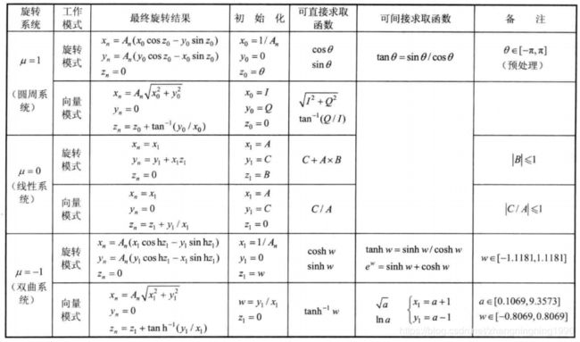
下面是VIVADO中CORDIC IP中可以计算的函数
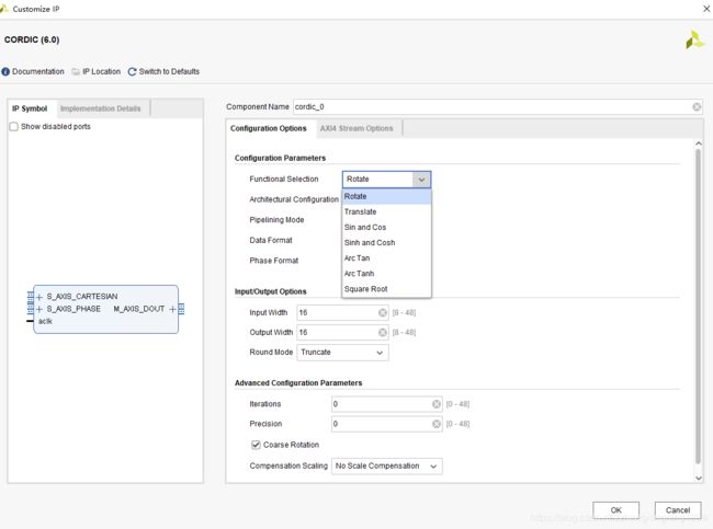
这里是不是可以看出上面的函数基本上是一一对应的。
CORDIC算法向量模式原理
CIRDIC算法向量模式推导步骤一
这里主要参考的是参考文献[1]中的文章,大家可以进行相应的阅读。
平面上一点在直角坐标系下的坐标(X,Y)=(100,200),如何求的在极坐标系下的坐标(ρ,θ)。用计算器计算一下可知答案是(223.61,63.435)。

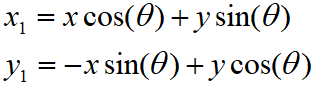
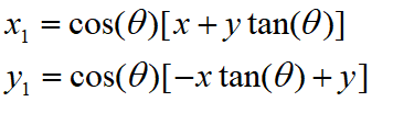
为了突出重点,这里我们只讨论X和Y都为正数的情况。这里或许有同学要说如果X和Y中有为负值的情况应该咋么办,其实这部分的算法不需要X和Y都为正值,但是需要X为正值。如果X为负值,那么我们便需要进行相应的处理,方法就是将X轴的值变成正值,但是这部分不要忘记CORDIC迭代的初始值发生变化。当X变成正值之后θ=atan(y/x)。求θ的过程也就是求atan 函数的过程。Cordic算法采用的想法很直接,将 ( x , y ) (x,y) (x,y)旋转一定的度数,如果旋转完纵坐标变为了0,那么旋转的度数就是θ。坐标旋转的公式可能大家都忘了,这里把公式列出了。设 ( x , y ) (x,y) (x,y)是原始坐标点,将其以原点为中心,顺时针旋转θ之后的坐标记为 ( x 1 , y 1 ) (x_1,y_1) (x1,y1),则有如下公式:
这里要明确我们的目标是为了将 y y y变成零,为了减少计算量,都是先用二分法进行旋转,也就是说第一次旋转45度,至于是顺时针旋转还是逆时针旋转取决于 y y y的符号。

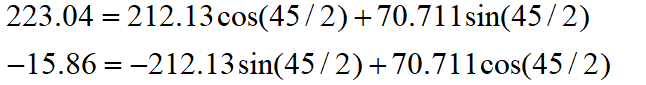
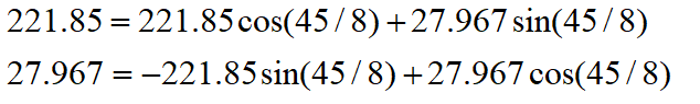
旋转之后纵坐标为70.71,还是大于0,说明旋转的度数不够,接着再旋转22.5度。
这时总共旋转了45+22.5=67.5度。结果纵坐标变为了负数,说明θ<67.5度,这时就要往回转,还是二分查找法的思想,这次转11.25度。

这时总共旋转了45+22.5-11.25=56.25度。又转过头了,接着旋转,这次顺时针转5.625度。
这时总共旋转了45+22.5-11.25+5.625=61.875度。这时纵坐标已经很接近0了。我们只是说明算法的思想,因此就不接着往下计算了。计算到这里我们给的答案是 61.875±5.625。二分查找法本质上查找的是一个区间,因此我们给出的是θ值的一个范围。同时,坐标到原点的距离ρ也求出来了,ρ=223.52。与标准答案比较一下计算的结果还是可以的。旋转的过程图示如下。

可能有读者会问,计算中用到了 sin 函数和 cos 函数,这些值又是怎么计算呢。很简单,我们只用到很少的几个特殊点的sin 函数和 cos 函数的值,提前计算好存起来,用查找表。这里需要注意,这种思想在FPGA中非常容易遇见。
将上面的思想我们使用MATLAB来实现如下:
clc;
clear all;
sine = [0.7071067811865,0.3826834323651,0.1950903220161,0.09801714032956,0.04906767432742,0.02454122852291,0.01227153828572,0.006135884649154,0.003067956762966,0.001533980186285,7.669903187427045e-4,3.834951875713956e-4,1.917475973107033e-4,9.587379909597735e-5,4.793689960306688e-5,2.396844980841822e-5];
cosine = [0.7071067811865,0.9238795325113,0.9807852804032,0.9951847266722, ...
0.9987954562052,0.9996988186962,0.9999247018391,0.9999811752826,0.9999952938096, ...
0.9999988234517,0.9999997058629,0.9999999264657,0.9999999816164,0.9999999954041, ...
0.999999998851,0.9999999997128];
angle = 45;
a = zeros(16,1);
for i = 1:16
a(i) = angle;
angle = angle/2;
end
x = 100;
y = -300;
z = 0;
for i = 1:16
if(y > 0)
x_new = x*cosine(i) + y*sine(i);
y_new = y*cosine(i) - x*sine(i);
x = x_new;
y = y_new;
z = z + a(i);
else
x_new = x*cosine(i) - y*sine(i);
y_new = y*cosine(i) + x*sine(i);
x = x_new;
y = y_new;
z = z - a(i);
end
end
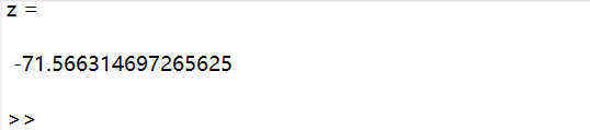
z
结果如下:

CIRDIC算法向量模式推导步骤二
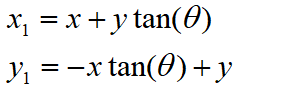
CORDIC一般是在FPGA中实现。FPGA中的DSP资源是非常宝贵的资源,所以我们要尽可能减少CORDIC中的乘法的个数,所以将公式变形如下:
这里因为我们要计算相位 a r c t a n ( y / x ) arctan(y/x) arctan(y/x),所以我们先将缩放因子去掉

但是我们注意到 CIRDIC算法向量模式不仅可以计算 a r c t a n ( y / x ) arctan(y/x) arctan(y/x)而且可以计算 x 2 + y 2 \sqrt{x^2+y^2} x2+y2,所以这个补偿因子到最后肯定会补偿回来,在FPGA中同样利用查表得方法补偿回来。
省略cos(θ)后发生了什么呢,每次旋转后的新坐标点到原点的距离都变长了,放缩的系数是1/cos(θ)。不过没有关系,我们求的是θ,不关心ρ的改变。这样的变形非常的简单,但是每次循环的运算量一下就从4次乘法降到了2次乘法了。
将上面的思想我们使用MATLAB来实现如下:
clc;
clear all;

tangent = [1.0,0.4142135623731,0.1989123673797,0.09849140335716,0.04912684976947, ...
0.02454862210893,0.01227246237957,0.006136000157623,0.003067971201423, ...
0.001533981991089,7.669905443430926e-4,3.83495215771441e-4,1.917476008357089e-4, ...
9.587379953660303e-5,4.79368996581451e-5,2.3968449815303e-5];
angle = 45;
a = zeros(16,1);
for i = 1:16
    a(i) = angle;
    angle = angle/2;
end

 x = 100;
 y = -300;
 z = 0;

for i = 1:16
    if(y > 0)
        x_new = x+ y*tangent(i);
        y_new = y - x*tangent(i);
        x = x_new;
        y = y_new;
        z = z + a(i);
    else
        x_new = x- y*tangent(i);
        y_new = y + x*tangent(i);
        x = x_new;
        y = y_new;
        z = z - a(i);
    end
end
z
结果与公式变形前得结果一摸一样,进而说明了我们实验得正确性。
CIRDIC算法向量模式推导步骤三
在FPGA中多得是寄存器查找表等资源,DSP资源非常少,所以我们要尽可能得消除CORDIC中得乘法,消除得方法是变下面公式中得乘法为移位操作:
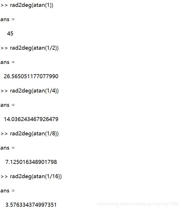
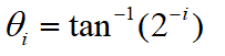
所以我们要求 t a n ( θ ) tan(θ) tan(θ)是2得负整数次幂。然后我们对上面得式子进行分析:
第一次循环时,tan(45)=1,所以第一次循环实际上是不需要乘法运算的。第二次运算呢?
Tan(22.5)=0.4142135623731,很不幸,第二次循环乘数是个很不整的小数。是否能对其改造一下呢?答案是肯定的。第二次选择22.5度是因为二分查找法的查找效率最高。如果选用个在22.5到45度之间的值,查找的效率会降低一些。如果稍微降低一点查找的效率能让我们有效的减少乘法的次数,使最终的计算速度提高了,那么这种改进就是值得的。
我们发现tan(26.565051177078)=0.5,如果我们第二次旋转采用26.565051177078度,那么乘数变为0.5,如果我们采用定点数运算的话(没有浮点协处理器时为了加速计算我们会大量的采用定点数算法)乘以0.5就相当于将乘数右移一位。右移运算是很快的,这样第二次循环中的乘法运算也被消除了。
类似的方法,第三次循环中不用11.25度,而采用 14.0362434679265 度。
Tan(14.0362434679265)= 1/4
乘数右移两位就可以了。剩下的都以此类推。
所以我们给出相应的MATLAB代码:
clc;
clear all;

angle = [45.0, 26.565051177078, 14.0362434679265, 7.1250163489018, 3.57633437499735, ...
                            1.78991060824607, 0.8951737102111, 0.4476141708606, 0.2238105003685, 0.1119056770662, ...
                            0.0559528918938, 0.027976452617, 0.01398822714227, 0.006994113675353, 0.003497056850704,0.001748528426980];

tangent = [1.0, 1 / 2.0, 1 / 4.0, 1 / 8.0, 1 / 16.0, ...
                              1 / 32.0, 1 / 64.0, 1 / 128.0, 1 / 256.0, 1 / 512.0, ...
                              1 / 1024.0, 1 / 2048.0, 1 / 4096.0, 1 / 8192.0, 1 / 16384.0,1/32768];


 x = 100;
 y = -300;
 z = 0;

for i = 1:16
    if(y > 0)
        x_new = x+ y*tangent(i);
        y_new = y - x*tangent(i);
        x = x_new;
        y = y_new;
        z = z + angle(i);
    else
        x_new = x- y*tangent(i);
        y_new = y + x*tangent(i);
        x = x_new;
        y = y_new;
        z = z - angle(i);
    end
end
z
上面的程序由于MATLAB本身不利于移位操作,所以我们也就乘以了相应的数,但这点在FPGA中是相当容易操作的。
运行结果如下:

到这里 CORDIC 算法的最核心的思想就介绍完了。当然,这里介绍的只是CORDIC算法最基本的内容,实际上,利用CORDIC 算法不光可以计算 atan 函数,其他的像 Sin,Cos,Sinh,Cosh 等一系列的函数都可以计算。
CIRDIC算法向量模式推导步骤三
上面为计算过程中我们将 c o s ( θ ) cos(θ) cos(θ)省略,所以为了计算 x 2 + y 2 \sqrt{x^2+y^2} x2+y2,所以这个补偿因子到最后肯定会补偿回来。因为每次推导我们都省略了 c o s ( θ ) cos(θ) cos(θ),所以我们最终的真实值 ( x n 1 , y n 1 ) (x_{n1},y_{n1}) (xn1,yn1)需要进行的缩放处理如下:

由前面可知:
所以:

若总的旋转次数为n, 则总的模长补偿因子K可表示为:
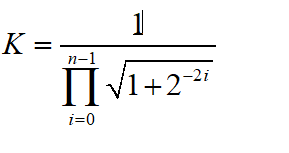
当n趋于无穷大时,K 逼近 0.607252935。
对应的MATLAB程序如下:
clc;
clear all;

angle = [45.0, 26.565051177078, 14.0362434679265, 7.1250163489018, 3.57633437499735, ...
                            1.78991060824607, 0.8951737102111, 0.4476141708606, 0.2238105003685, 0.1119056770662, ...
                            0.0559528918938, 0.027976452617, 0.01398822714227, 0.006994113675353, 0.003497056850704,0.001748528426980];

tangent = [1.0, 1 / 2.0, 1 / 4.0, 1 / 8.0, 1 / 16.0, ...
                              1 / 32.0, 1 / 64.0, 1 / 128.0, 1 / 256.0, 1 / 512.0, ...
                              1 / 1024.0, 1 / 2048.0, 1 / 4096.0, 1 / 8192.0, 1 / 16384.0,1/32768];


 x = 100;
 y = -300;
 z = 0;

for i = 1:16
    if(y > 0)
        x_new = x+ y*tangent(i);
        y_new = y - x*tangent(i);
        x = x_new;
        y = y_new;
        z = z + angle(i);
    else
        x_new = x- y*tangent(i);
        y_new = y + x*tangent(i);
        x = x_new;
        y = y_new;
        z = z - angle(i);
    end
end
K = 1;
for i = 1:16
    K = K*1/sqrt(1+2^-(2*(i-1)));
end
x_new = x_new*K

z
运行结果如下:

从上面可以验证我们实验的正确性,并且K值在实际FPGA中也是进行查表而不是上面程序那样计算。
MATLAB实现
上面的MATLAB代码知识为了验证我们的推导过程专门写的代码,这样写的代码没办法与FPGA内部生成的代码一一对应起来,其中最主要的原因也是因为没有对数据进行相应的量化操作,也没有在程序中进行相应的预处理操作。所以接下来给出相应的完整的代码,这部分代码参考了电子发烧友,本来想自己写,但是架不住别人写的代码太好,相应的链接已经在参考文献中给出,需要的同学可以自己学习。
clc;
clear all;
Ninter = 12;%迭代次数
N = 32;
%y: y坐标值(Q(N,N-2))
%x: x坐标值(Q(N,N-2))
%angle:Q(18,15)
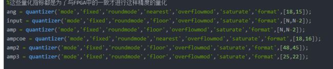
%这些量化指标都是为了与FPGA中的一致才进行这样精度的量化
ang = quantizer('mode','fixed','roundmode','nearest','overflowmod','saturate','format',[18,15]);
input = quantizer('mode','fixed','roundmode','floor','overflowmod','saturate','format',[N,N-2]);
amp = quantizer('mode','fixed','roundmode','floor','overflowmod','saturate','format',[N,N-2]);
ampcoe = quantizer('mode','fixed','roundmode','nearest','overflowmod','saturate','format',[18,16]);
amp2 = quantizer('mode','fixed','roundmode','floor','overflowmod','saturate','format',[48,45]);
amp3 = quantizer('mode','fixed','roundmode','floor','overflowmod','saturate','format',[25,22]);
times = 100;
num=0;
fid1 = fopen('x_random_fpga.txt','r');
x_fix = fscanf(fid1,'%d');
x_fix = x_fix/2^(N-2);
fid1 = fopen('y_random_fpga.txt','r');
y_fix = fscanf(fid1,'%d');
y_fix = y_fix/2^(N-2);
PreciseAng_data = zeros(1,times);
PreciseAmp_data = zeros(1,times);
Ang_data=zeros(1,times);
Amp_data=zeros(1,times);
for t=1:times
num=num+1;
x = x_fix(t);
y= y_fix(t);
K = zeros(1,Ninter+1);
K(1) = 1;
for i=2:Ninter + 1
K(i) = K(i-1)*sqrt(1+2^(-2*i+4));
end
K = quantize(ampcoe,1./K);
y1 =y;
z = 0;
x1 = abs(x);
x1 = x1;
y1 = y1;
d = -sign(y1);
atan_z = zeros(1,Ninter);
atan_z_dectobin =zeros(Ninter,15);
for i=0:Ninter-1
atan_z(i+1) = quantize(ang,atan(2^(-i)));
end
for n=0:Ninter-1
if(y1 == 0)
break;
end
x1_q = quantize(amp2,(2^(-n)*x1));
y1_q = quantize(amp2,(2^(-n)*y1));%(48,45)
x1 = quantize(amp2,x1 - d*y1_q);
y1 = quantize(amp2,y1 + d*x1_q);
atan_z_qu = quantize(ang,atan_z(n+1));
z = quantize(ang,z - d*atan_z_qu);
atan_zzz = atan_z_qu*2^15;
z_comp =z*2^15;
d = -sign(y1);
end
%坐标点预处理
pi_quan = quantize(ang,pi);
if(x < 0)
if(y < 0)
Ang = -z - pi_quan ;
else
Ang = - z + pi_quan ;
end
else
Ang = z;
end
Ang_q =Ang*2^15;
x1 = quantize(amp3,x1);%(25,21)这些是与FPGA中的量化代码相互对应的部分
Amp = quantize(amp,x1*K(n+1));%K(18,16)
Amp_q = Amp*2^(N-2);
err = Ang - angle(x + j*y);
PreciseAng = log2(abs(err));
err = Amp - abs(x+j*y);
PreciseAmp = log2(abs(err));
Ang_data(t)=Ang_q;
Amp_data(t)=Amp_q;
PreciseAng_data(t)=PreciseAng;
PreciseAmp_data(t)=PreciseAmp;
if(PreciseAng_data(t)==0)
break;
end
if(PreciseAmp_data(t)==0)
break;
end
end
PreciseAng_s_max = max(PreciseAng_data)
PreciseAmp_s_max = max(PreciseAmp_data)
fid_ang = fopen('Ang_matlab.txt','w');
fprintf(fid_ang,'%d\n',Ang_data);
fid_amp = fopen('Amp_matlab.txt','w');
fprintf(fid_amp,'%d\n',Amp_data);
然后对比一下100个数据之后算法计算的最大误差:

上面的结果是将数据转换成dB的格式,所以说上面的算法处理的是正确的。
上面的难点在意量化操作再FPGA中实现的方式:
在下面FPGA实现的时候我们会进行相应的介绍。
FPGA实现
其实上面代码的FPGA实现是非常容易的,FPGA的程序是在电子发烧友的基础上改的,为了尊重原作者,大家可以购买相应的课程,课程里面的代码都非常棒,我也只是改了一小部分。接下来的代码其实如果想简单点就可以不使用DSP原语而是直接使用组合逻辑或者IP完成相应的操作。其实关于CORDIC算法的Verilog实现博主19年的时候写过,还是比较容易的,但是却没办法与MATLAB相互验证,也没办法控制DSP资源的复用,通过该课程的学习我真正掌握了MATLAB与FPGA的相互验证方法。这一部分由于我只是做了稍微一点改动,所以原作者的信息在博客中保留。
`timescale 1ns / 1ps
////////////////////////////////////////////////////////////////////////////////
// Company: MYMINIEYE
// Engineer:Mill
//
// Create Date: 2016/12/29 14:26:00
// Design Name: CORDICang_stream
// Module Name: CORDICang_vector_ip
// Project Name: FS_cofdm_rx_v00
// Target Device: zc7045
// Tool versions: vivado 2015.1
// Description: Cordic
//
//
//
// Dependencies:
//
// Revision:v02
// Revision 0.01 - File Created
// Additional Comments: contact us: [email protected]
//
////////////////////////////////////////////////////////////////////////////////
module CORDICang_vector_ip #
(
parameter Ninter = 13,
parameter N = 32
)
(
input sclk ,
input rst_n ,
input [N-1:0] x ,
input [N-1:0] y ,
input valid ,
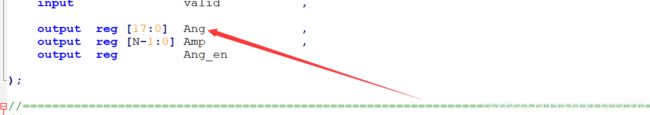
output reg [17:0] Ang ,
output reg [N-1:0] Amp ,
output reg Ang_en
);
//========================================================================================\
//************** Main Code **********************************
//========================================================================================/
/*===================================================================
====================================================================*/
reg valid_d ;
reg valid_a ;
reg [N-1:0] x_a ;
reg [N-1:0] y_a ;
reg [ 4:0] cordic_cnt ;
always @(posedge sclk)
valid_d <= valid;
always @(posedge sclk)
if(!rst_n)
valid_a <= 1'b0;
else if(valid && valid_d==1'b0)
valid_a <= 1'b1;
else if(cordic_cnt == 5'd29)
valid_a <= 1'b0;
always @(posedge sclk)
if(!valid_a)
cordic_cnt <= 3'd0;
else
cordic_cnt <= cordic_cnt + 1'b1;
always @(posedge sclk)
if(valid&&valid_d==1'b0)begin
x_a <= x;
y_a <= y;
end
/*===================================================================
====================================================================*/
reg [ 4:0] Ninter_cnt ;
reg [ 4:0] Ninter_cnt_copy1;
wire [17:0] K_quantize ;
wire [17:0] atanz ;
reg valid_reg ;
reg [47:0] x1 ;
wire [47:0] x_reg_dsp_x1 ;
reg [47:0] y1 ;
wire [47:0] y_reg_dsp_y1 ;
reg x1_add_en ;
reg y1_add_en ;
reg [17:0] z ;
wire [17:0] z_dsp_lut ;
reg [17:0] z_dsp_lut_delay1;
wire [29:0] A_IN_x1 ;
reg [17:0] B_IN_x1 ;
reg [47:0] C_x1 ;
wire [24:0] D ;
wire [47:0] P_x1 ;
reg [24:0] x1_mux ;
reg [ 6:0] OPMODE_x1 ;
reg [ 3:0] ALUMODE_x1 ;
reg [ 4:0] INMODE_x1 ;
reg [ 6:0] OPMODE_y1 ;
reg [ 3:0] ALUMODE_y1 ;
wire [ 4:0] INMODE_y1 ;
reg [29:0] A_IN_y1 ;
reg [17:0] B_IN_y1 ;
reg [47:0] C_y1 ;
wire [47:0] P_y1 ;
reg [47:0] shift_y_reg ;
reg [47:0] shift_x_reg ;
reg break_out ;
reg break_happen ;
wire break_cal ;
reg cal_control ;
reg first_break_happen ;
always @(posedge sclk)
if(!rst_n)
cal_control <= 1'b0;
else if(valid_a)
cal_control <= ~cal_control;
always @(*)//这个信号没有用处
if(Ninter_cnt_copy1 != 0 && break_cal && cal_control == 1'b0)
break_happen = 1'b1;
else
break_happen = 1'b0;
always @(posedge sclk)
if(!rst_n)
first_break_happen <= 1'b0;
else if(break_happen)
first_break_happen <= 1'b1;
else if(Ninter_cnt_copy1 == 4'd14)
first_break_happen <= 1'b0;
/*===================================================================
====================================================================*/
reg x_sign,y_sign ;
reg Pos_valid ;
reg [3:0] k_addr ;
always @(posedge sclk)
valid_reg <= valid_a;
always @(posedge sclk)
if(!rst_n)
x_sign <= 1'b0;
else if(x_a[N-1]&&valid_a&&(~valid_reg))
x_sign <= 1'b1;
else if(x_a[N-1]==1'b0&&valid_a&&(~valid_reg))
x_sign <= 1'b0;
always @(posedge sclk)
if(!rst_n)
y_sign <= 1'b0;
else if(y_a[N-1]&&valid_a&&(~valid_reg))
y_sign <= 1'b1;
else if(y_a[N-1]==1'b0&&valid_a&&(~valid_reg))
y_sign <= 1'b0;
always @(posedge sclk)
if(!rst_n)
Pos_valid <= 1'b0;
else if(valid_a && (~valid_reg))
Pos_valid <= 1'b1;
else if(Ninter_cnt_copy1==5'h1f)
Pos_valid <= 1'b0;
always @(posedge sclk)
if(!rst_n||(!valid_a))
Ninter_cnt <= 4'd0;
else if(valid_a&&cal_control)
Ninter_cnt <= Ninter_cnt + 1'b1;
always @(posedge sclk)
if(!rst_n||(!valid_a))
Ninter_cnt_copy1 <= 4'd0;
else if(valid_a&&cal_control)
Ninter_cnt_copy1 <= Ninter_cnt_copy1 + 1'b1;
always @(posedge sclk)
if(!rst_n)
break_out <= 1'b0;
else if(break_happen==1'b1&&first_break_happen==1'b0)
break_out <= 1'b1;
else if(Ninter_cnt_copy1==4'd14)
break_out <= 1'b0;
always @(posedge sclk)
if(!rst_n)
k_addr <= 4'd0;
else if(y1[47:48-N]==32'd0)
k_addr <= 4'd0;
else if(break_happen&&first_break_happen==1'b0)
k_addr <= Ninter_cnt_copy1;
else if(!break_out)
k_addr <= Ninter;
K_quantize_dis_rom #(
.ROM_WIDTH (18 ),
.ROM_ADDR_BITS (4 ),
.ROM_DEPTH (16 )
) u_K_quantize_dis_rom(
.clock (sclk ),
.enable (1'b1 ),
.address (k_addr ),
.output_data (K_quantize )
);
atan_z_dis_rom #(
.ROM_WIDTH (18 ),
.ROM_ADDR_BITS (4 ),
.ROM_DEPTH (16 )
)u_atan_z_dis_rom(
.clock (sclk ),
.enable (1'b1 ),
.address (Ninter_cnt_copy1[3:0] ),
.output_data (atanz )
);
/*===================================================================
====================================================================*/
reg [N-1:0] x_abs ;
always @(posedge sclk)
if(x_a[N-1]==1)
x_abs <= (~x_a)+1'b1;
else
x_abs <= x_a;
/*===================================================================
====================================================================*/
always @(posedge sclk)
case(Ninter_cnt[3:0])
4'd0:shift_y_reg <= {{2{y_a[N-1]}},{y_a[N-2:0]},{(47-N){1'b0}}};//floor
4'd1: if(cal_control==1'b0)shift_y_reg <= {y_reg_dsp_y1[47],{1{y_reg_dsp_y1[47]}},y_reg_dsp_y1[46:1]};//floor
4'd2: if(cal_control==1'b0)shift_y_reg <= {y_reg_dsp_y1[47],{2{y_reg_dsp_y1[47]}},y_reg_dsp_y1[46:2]};//floor
4'd3: if(cal_control==1'b0)shift_y_reg <= {y_reg_dsp_y1[47],{3{y_reg_dsp_y1[47]}},y_reg_dsp_y1[46:3]};//floor
4'd4: if(cal_control==1'b0)shift_y_reg <= {y_reg_dsp_y1[47],{4{y_reg_dsp_y1[47]}},y_reg_dsp_y1[46:4]};//floor
4'd5: if(cal_control==1'b0)shift_y_reg <= {y_reg_dsp_y1[47],{5{y_reg_dsp_y1[47]}},y_reg_dsp_y1[46:5]};//floor
4'd6: if(cal_control==1'b0)shift_y_reg <= {y_reg_dsp_y1[47],{6{y_reg_dsp_y1[47]}},y_reg_dsp_y1[46:6]};//floor
4'd7: if(cal_control==1'b0)shift_y_reg <= {y_reg_dsp_y1[47],{7{y_reg_dsp_y1[47]}},y_reg_dsp_y1[46:7]};//floor
4'd8: if(cal_control==1'b0)shift_y_reg <= {y_reg_dsp_y1[47],{8{y_reg_dsp_y1[47]}},y_reg_dsp_y1[46:8]};//floor
4'd9: if(cal_control==1'b0)shift_y_reg <= {y_reg_dsp_y1[47],{9{y_reg_dsp_y1[47]}},y_reg_dsp_y1[46:9]};//floor
4'd10:if(cal_control==1'b0)shift_y_reg <= {y_reg_dsp_y1[47],{10{y_reg_dsp_y1[47]}},y_reg_dsp_y1[46:10]};//floor
4'd11:if(cal_control==1'b0)shift_y_reg <= {y_reg_dsp_y1[47],{11{y_reg_dsp_y1[47]}},y_reg_dsp_y1[46:11]};//floor
4'd12:if(cal_control==1'b0)shift_y_reg <= {y_reg_dsp_y1[47],{12{y_reg_dsp_y1[47]}},y_reg_dsp_y1[46:12]};//floor
4'd13:if(cal_control==1'b0)shift_y_reg <= {y_reg_dsp_y1[47],{13{y_reg_dsp_y1[47]}},y_reg_dsp_y1[46:13]};//floor
4'd14:if(cal_control==1'b0)shift_y_reg <= {y_reg_dsp_y1[47],{14{y_reg_dsp_y1[47]}},y_reg_dsp_y1[46:14]};//floor
4'd15:if(cal_control==1'b0)shift_y_reg <= {y_reg_dsp_y1[47],{15{y_reg_dsp_y1[47]}},y_reg_dsp_y1[46:15]};//floor
default:shift_y_reg <= shift_y_reg;
endcase
always @(posedge sclk)
case(Ninter_cnt[3:0])
4'd0:shift_x_reg <= {{2{x_abs[N-1]}},{x_abs[N-2:0]},{(47-N){1'b0}}};
4'd1:if(cal_control==1'b0)shift_x_reg <= {x_reg_dsp_x1[47],{1{x_reg_dsp_x1[47]}},x_reg_dsp_x1[46:1]};//floor
4'd2:if(cal_control==1'b0)shift_x_reg <= {x_reg_dsp_x1[47],{2{x_reg_dsp_x1[47]}},x_reg_dsp_x1[46:2]};//floor
4'd3:if(cal_control==1'b0)shift_x_reg <= {x_reg_dsp_x1[47],{3{x_reg_dsp_x1[47]}},x_reg_dsp_x1[46:3]};//floor
4'd4:if(cal_control==1'b0)shift_x_reg <= {x_reg_dsp_x1[47],{4{x_reg_dsp_x1[47]}},x_reg_dsp_x1[46:4]};//floor
4'd5:if(cal_control==1'b0)shift_x_reg <= {x_reg_dsp_x1[47],{5{x_reg_dsp_x1[47]}},x_reg_dsp_x1[46:5]};//floor
4'd6:if(cal_control==1'b0)shift_x_reg <= {x_reg_dsp_x1[47],{6{x_reg_dsp_x1[47]}},x_reg_dsp_x1[46:6]};//floor
4'd7:if(cal_control==1'b0)shift_x_reg <= {x_reg_dsp_x1[47],{7{x_reg_dsp_x1[47]}},x_reg_dsp_x1[46:7]};//floor
4'd8:if(cal_control==1'b0)shift_x_reg <= {x_reg_dsp_x1[47],{8{x_reg_dsp_x1[47]}},x_reg_dsp_x1[46:8]};//floor
4'd9:if(cal_control==1'b0)shift_x_reg <= {x_reg_dsp_x1[47],{9{x_reg_dsp_x1[47]}},x_reg_dsp_x1[46:9]};//floor
4'd10:if(cal_control==1'b0)shift_x_reg <= {x_reg_dsp_x1[47],{10{x_reg_dsp_x1[47]}},x_reg_dsp_x1[46:10]};//floor
4'd11:if(cal_control==1'b0)shift_x_reg <= {x_reg_dsp_x1[47],{11{x_reg_dsp_x1[47]}},x_reg_dsp_x1[46:11]};//floor
4'd12:if(cal_control==1'b0)shift_x_reg <= {x_reg_dsp_x1[47],{12{x_reg_dsp_x1[47]}},x_reg_dsp_x1[46:12]};//floor
4'd13:if(cal_control==1'b0)shift_x_reg <= {x_reg_dsp_x1[47],{13{x_reg_dsp_x1[47]}},x_reg_dsp_x1[46:13]};//floor
4'd14:if(cal_control==1'b0)shift_x_reg <= {x_reg_dsp_x1[47],{14{x_reg_dsp_x1[47]}},x_reg_dsp_x1[46:14]};//floor
4'd15:if(cal_control==1'b0)shift_x_reg <= {x_reg_dsp_x1[47],{15{x_reg_dsp_x1[47]}},x_reg_dsp_x1[46:15]};//floor
default:shift_x_reg <= shift_x_reg;
endcase
/*=============================================================================
x1 = x_reg - d*(shift(n+1)*y_reg); and Amp = quantize(q_amp,x1*K(n+1));
DSP X1: add/sub and mult; MUX:P=(A:B)+/-C; P=B*D
==============================================================================*/
reg [47:0] x1_temp ;
reg [47:0] x_reg_dsp_x1_d ;
assign A_IN_x1 = shift_y_reg[47:18];
assign D = x1_temp[47:23];
assign x_reg_dsp_x1= P_x1;
always @(*)
if(Ninter_cnt==4'd0&&Pos_valid)
x1 = {{2{x_abs[N-1]}},{x_abs[N-2:0]},{(47-N){1'b0}}};
else
x1 = x_reg_dsp_x1;
always @(posedge sclk)
if(y1[47:48-N]==32'd0)//y1[47:48-N]==32'd0||break_out
x1_temp <= {{2{x_abs[N-1]}},{x_abs[N-2:0]},{(47-N){1'b0}}};
else if(break_happen == 1'b1)
x1_temp <= x_reg_dsp_x1;
else if(cal_control==1'b0 && break_out==1'b0 && Ninter_cnt==Ninter)//if(break_happen&&first_break_happen==1'b0)
x1_temp <= x_reg_dsp_x1;
always @(posedge sclk)
y1 <= {{2{y_a[N-1]}},{y_a[N-2:0]},{(47-N){1'b0}}};//x1 <= {4'b0000,{x[N-2:0]},{(45-N){1'b0}}};//
always @(posedge sclk)
if(y_a[N-1]==1'b0 && Ninter_cnt==0)
x1_add_en <= 1'b1;
else if(y_a[N-1]==1'b1 && Ninter_cnt==0)
x1_add_en <= 1'b0;
else if(y_reg_dsp_y1[47]==1'b1&&cal_control==1'b0)
x1_add_en <= 1'b0;
else if(y_reg_dsp_y1[47]==1'b0&&cal_control==1'b0)
x1_add_en <= 1'b1;
else
x1_add_en <= x1_add_en;
always @(posedge sclk)
if(Ninter_cnt==Ninter||break_out)
x1_mux <= x1[47:23];
else
x1_mux <= 25'd0;
always @(posedge sclk)
x_reg_dsp_x1_d <= x_reg_dsp_x1;
always @(*)
if(Ninter_cnt>=Ninter||break_out)
B_IN_x1 = K_quantize;
else if(cal_control<Ninter&&cal_control)
B_IN_x1 = shift_y_reg[17:0];
else
B_IN_x1 = 18'd0;
always @(*)
if(Ninter_cnt==0 && cal_control)
C_x1 = {{2{x_abs[N-1]}},{x_abs[N-2:0]},{(47-N){1'b0}}};
else if(cal_control == 1'b1)
C_x1 = x_reg_dsp_x1_d;
else
C_x1 = 48'd0;
always @(*)
if(Ninter_cnt>=Ninter)
OPMODE_x1 = 7'b000_01_01;//B*D
else if(x1_add_en == 1'b1)//C+(A:B)
OPMODE_x1 = 7'b000_11_11;
else
OPMODE_x1 = 7'b011_00_11;//C-(A:B)
always @(posedge sclk)
if(Ninter_cnt>=Ninter-2)
INMODE_x1 <= 5'b00110;
else
INMODE_x1 <= 5'b00000;
always @(*)
if(Ninter_cnt>=Ninter)
ALUMODE_x1 = 4'b0000;
else if(x1_add_en == 1'b1)
ALUMODE_x1 = 4'b0000;
else
ALUMODE_x1 = 4'b0011;
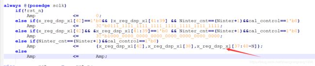
always @(posedge sclk)
if(!rst_n)
Amp <= 0;
else if(x_reg_dsp_x1[42]==1'b0&& |x_reg_dsp_x1[41:39] && Ninter_cnt==(Ninter+1)&&cal_control==1'b0)
Amp <= 32'b0111_1111_1111_1111_1111_1111_1111_1111;
else if(x_reg_dsp_x1[42]&& &x_reg_dsp_x1[41:39]==1'b0 && Ninter_cnt==(Ninter+1)&&cal_control==1'b0)
Amp <= 32'b1000_0000_0000_0000_0000_0000_0000_0000;
else if(Ninter_cnt==(Ninter+1)&&cal_control==1'b0)
Amp <= {x_reg_dsp_x1[42],x_reg_dsp_x1[38],x_reg_dsp_x1[37:40-N]};
else
Amp <= Amp;
wire rst = ~rst_n;
wire rst_x ;
assign rst_x = ~rst_n;
DSP48E1 #(
// Feature Control Attributes: Data Path Selection
.A_INPUT("DIRECT"), // Selects A input source, "DIRECT" (A port) or "CASCADE" (ACIN port)
.B_INPUT("DIRECT"), // Selects B input source, "DIRECT" (B port) or "CASCADE" (BCIN port)
.USE_DPORT("TRUE"), // Select D port usage (TRUE or FALSE)
.USE_MULT("DYNAMIC"), // Select multiplier usage ("MULTIPLY", "DYNAMIC", or "NONE")
.USE_SIMD("ONE48"), // SIMD selection ("ONE48", "TWO24", "FOUR12")
// Pattern Detector Attributes: Pattern Detection Configuration
.AUTORESET_PATDET("NO_RESET"), // "NO_RESET", "RESET_MATCH", "RESET_NOT_MATCH"
.MASK(48'h3fffffffffff), // 48-bit mask value for pattern detect (1=ignore)
.PATTERN(48'h000000000000), // 48-bit pattern match for pattern detect
.SEL_MASK("MASK"), // "C", "MASK", "ROUNDING_MODE1", "ROUNDING_MODE2"
.SEL_PATTERN("PATTERN"), // Select pattern value ("PATTERN" or "C")
.USE_PATTERN_DETECT("NO_PATDET"), // Enable pattern detect ("PATDET" or "NO_PATDET")
// Register Control Attributes: Pipeline Register Configuration
.ACASCREG(0), // Number of pipeline stages between A/ACIN and ACOUT (0, 1 or 2)
.ADREG(0), // Number of pipeline stages for pre-adder (0 or 1)
.ALUMODEREG(0), // Number of pipeline stages for ALUMODE (0 or 1)
.AREG(0), // Number of pipeline stages for A (0, 1 or 2)
.BCASCREG(0), // Number of pipeline stages between B/BCIN and BCOUT (0, 1 or 2)
.BREG(0), // Number of pipeline stages for B (0, 1 or 2)
.CARRYINREG(0), // Number of pipeline stages for CARRYIN (0 or 1)
.CARRYINSELREG(0), // Number of pipeline stages for CARRYINSEL (0 or 1)
.CREG(0), // Number of pipeline stages for C (0 or 1)
.DREG(0), // Number of pipeline stages for D (0 or 1)
.INMODEREG(1), // Number of pipeline stages for INMODE (0 or 1)
.MREG(0), // Number of multiplier pipeline stages (0 or 1)
.OPMODEREG(0), // Number of pipeline stages for OPMODE (0 or 1)
.PREG(1) // Number of pipeline stages for P (0 or 1)
)
DSP48E1_cal_x1 (
// Cascade: 30-bit (each) output: Cascade Ports
.ACOUT(), // 30-bit output: A port cascade output
.BCOUT(), // 18-bit output: B port cascade output
.CARRYCASCOUT(), // 1-bit output: Cascade carry output
.MULTSIGNOUT(), // 1-bit output: Multiplier sign cascade output
.PCOUT(), // 48-bit output: Cascade output
// Control: 1-bit (each) output: Control Inputs/Status Bits
.OVERFLOW(), // 1-bit output: Overflow in add/acc output
.PATTERNBDETECT(), // 1-bit output: Pattern bar detect output
.PATTERNDETECT(), // 1-bit output: Pattern detect output
.UNDERFLOW(), // 1-bit output: Underflow in add/acc output
// Data: 4-bit (each) output: Data Ports
.CARRYOUT(), // 4-bit output: Carry output
.P(P_x1), // 48-bit output: Primary data output
// Cascade: 30-bit (each) input: Cascade Ports
.ACIN(30'd0), // 30-bit input: A cascade data input
.BCIN(18'd0), // 18-bit input: B cascade input
.CARRYCASCIN(1'b0), // 1-bit input: Cascade carry input
.MULTSIGNIN(1'b0), // 1-bit input: Multiplier sign input
.PCIN(48'd0), // 48-bit input: P cascade input
// Control: 4-bit (each) input: Control Inputs/Status Bits
.ALUMODE(ALUMODE_x1), // 4-bit input: ALU control input
.CARRYINSEL(3'b000), // 3-bit input: Carry select input
.CLK(sclk), // 1-bit input: Clock input
.INMODE(INMODE_x1), // 5-bit input: INMODE control input
.OPMODE(OPMODE_x1), // 7-bit input: Operation mode input
// Data: 30-bit (each) input: Data Ports
.A(A_IN_x1), // 30-bit input: A data input //A_IN
.B(B_IN_x1), // 18-bit input: B data input //B_IN
.C(C_x1), // 48-bit input: C data input
.CARRYIN(1'b0), // 1-bit input: Carry input signal
.D(D), // 25-bit input: D data input
// Reset/Clock Enable: 1-bit (each) input: Reset/Clock Enable Inputs
.CEA1(1'b1), // 1-bit input: Clock enable input for 1st stage AREG
.CEA2(1'b0), // 1-bit input: Clock enable input for 2nd stage AREG
.CEAD(1'b0), // 1-bit input: Clock enable input for ADREG
.CEALUMODE(1'b1), // 1-bit input: Clock enable input for ALUMODE
.CEB1(1'b1), // 1-bit input: Clock enable input for 1st stage BREG
.CEB2(1'b0), // 1-bit input: Clock enable input for 2nd stage BREG
.CEC(1'b1), // 1-bit input: Clock enable input for CREG
.CECARRYIN(1'b0), // 1-bit input: Clock enable input for CARRYINREG
.CECTRL(1'b1), // 1-bit input: Clock enable input for OPMODEREG and CARRYINSELREG
.CED(1'b1), // 1-bit input: Clock enable input for DREG
.CEINMODE(1'b1), // 1-bit input: Clock enable input for INMODEREG
.CEM(1'b1), // 1-bit input: Clock enable input for MREG
.CEP(1'b1), // 1-bit input: Clock enable input for PREG
.RSTA(rst_x), // 1-bit input: Reset input for AREG
.RSTALLCARRYIN(rst_x), // 1-bit input: Reset input for CARRYINREG
.RSTALUMODE(rst_x), // 1-bit input: Reset input for ALUMODEREG
.RSTB(rst_x), // 1-bit input: Reset input for BREG
.RSTC(rst_x), // 1-bit input: Reset input for CREG
.RSTCTRL(rst_x), // 1-bit input: Reset input for OPMODEREG and CARRYINSELREG
.RSTD(rst_x), // 1-bit input: Reset input for DREG and ADREG
.RSTINMODE(rst_x), // 1-bit input: Reset input for INMODEREG
.RSTM(rst_x), // 1-bit input: Reset input for MREG
.RSTP(rst_x) // 1-bit input: Reset input for PREG
);
/*===================================================================
y1 = y_reg + d*(shift(n+1)*x_reg);
====================================================================*/
wire [47:0] cal_x_abs ;
reg [47:0] y_reg_dsp_y1_d ;
assign cal_x_abs = {{2{x_abs[N-1]}},{x_abs[N-2:0]},{(47-N){1'b0}}};
assign y_reg_dsp_y1 = P_y1;
always @(posedge sclk)
if(y_a[N-1]==1'b0 && Ninter_cnt_copy1==0)
y1_add_en <= 1'b0;
else if(y_a[N-1]==1'b1 && Ninter_cnt_copy1==0)
y1_add_en <= 1'b1;
else if(y_reg_dsp_y1[47]==1'b1&&cal_control==1'b0)
y1_add_en <= 1'b1;
else if(y_reg_dsp_y1[47]==1'b0&&cal_control==1'b0)
y1_add_en <= 1'b0;
else
y1_add_en <= 1'b0;
always @(posedge sclk)
y_reg_dsp_y1_d <= y_reg_dsp_y1;
always @(*)
if(Ninter_cnt_copy1==0&&cal_control)
A_IN_y1 = cal_x_abs[47:18];
else if(cal_control)
A_IN_y1 = shift_x_reg[47:18];
else
A_IN_y1 = 30'd0;
always @(*)
if(Ninter_cnt_copy1==0&&cal_control)
B_IN_y1 = cal_x_abs[17:0];
else if(cal_control == 1'b1)
B_IN_y1 = shift_x_reg[17:0];
else
B_IN_y1 = 30'd0;
always @(*)
if(Ninter_cnt_copy1==0&&cal_control)
C_y1 = y1;
else if(cal_control)
C_y1 = y_reg_dsp_y1_d;
else
C_y1 = 30'd0;
/*=======================================================================
DSP y1 control :add sub and pattern
=======================================================================*/
assign INMODE_y1 = 5'b00000;
always @(*)
if(y1_add_en == 1'b1)//C+(A:B)
OPMODE_y1 = 7'b000_11_11;
else
OPMODE_y1 = 7'b011_00_11;//C-(A:B)
always @(*)
if(y1_add_en == 1'b1)
ALUMODE_y1 = 4'b0000;
else
ALUMODE_y1 = 4'b0011;
/*=======================================================================
DSP y1 control
=======================================================================*/
DSP48E1 #(
// Feature Control Attributes: Data Path Selection
.A_INPUT("DIRECT"), // Selects A input source, "DIRECT" (A port) or "CASCADE" (ACIN port)
.B_INPUT("DIRECT"), // Selects B input source, "DIRECT" (B port) or "CASCADE" (BCIN port)
.USE_DPORT("FALSE"), // Select D port usage (TRUE or FALSE)
.USE_MULT("NONE"), // Select multiplier usage ("MULTIPLY", "DYNAMIC", or "NONE")
.USE_SIMD("ONE48"), // SIMD selection ("ONE48", "TWO24", "FOUR12")
// Pattern Detector Attributes: Pattern Detection Configuration
.AUTORESET_PATDET("NO_RESET"), // "NO_RESET", "RESET_MATCH", "RESET_NOT_MATCH"
.MASK(48'd0), // 48-bit mask value for pattern detect (1=ignore)
.PATTERN(48'h000000000000), // 48-bit pattern match for pattern detect
.SEL_MASK("MASK"), // "C", "MASK", "ROUNDING_MODE1", "ROUNDING_MODE2"
.SEL_PATTERN("PATTERN"), // Select pattern value ("PATTERN" or "C")
.USE_PATTERN_DETECT("PATDET"), // Enable pattern detect ("PATDET" or "NO_PATDET")
// Register Control Attributes: Pipeline Register Configuration
.ACASCREG(0), // Number of pipeline stages between A/ACIN and ACOUT (0, 1 or 2)
.ADREG(0), // Number of pipeline stages for pre-adder (0 or 1)
.ALUMODEREG(0), // Number of pipeline stages for ALUMODE (0 or 1)
.AREG(0), // Number of pipeline stages for A (0, 1 or 2)
.BCASCREG(0), // Number of pipeline stages between B/BCIN and BCOUT (0, 1 or 2)
.BREG(0), // Number of pipeline stages for B (0, 1 or 2)
.CARRYINREG(0), // Number of pipeline stages for CARRYIN (0 or 1)
.CARRYINSELREG(0), // Number of pipeline stages for CARRYINSEL (0 or 1)
.CREG(0), // Number of pipeline stages for C (0 or 1)
.DREG(0), // Number of pipeline stages for D (0 or 1)
.INMODEREG(0), // Number of pipeline stages for INMODE (0 or 1)
.MREG(0), // Number of multiplier pipeline stages (0 or 1)
.OPMODEREG(0), // Number of pipeline stages for OPMODE (0 or 1)
.PREG(1) // Number of pipeline stages for P (0 or 1)
)
DSP48E1_cal_y1 (
// Cascade: 30-bit (each) output: Cascade Ports
.ACOUT(), // 30-bit output: A port cascade output
.BCOUT(), // 18-bit output: B port cascade output
.CARRYCASCOUT(), // 1-bit output: Cascade carry output
.MULTSIGNOUT(), // 1-bit output: Multiplier sign cascade output
.PCOUT(), // 48-bit output: Cascade output
// Control: 1-bit (each) output: Control Inputs/Status Bits
.OVERFLOW(), // 1-bit output: Overflow in add/acc output
.PATTERNBDETECT(), // 1-bit output: Pattern bar detect output
.PATTERNDETECT(break_cal), // 1-bit output: Pattern detect output
.UNDERFLOW(), // 1-bit output: Underflow in add/acc output
// Data: 4-bit (each) output: Data Ports
.CARRYOUT(), // 4-bit output: Carry output
.P(P_y1), // 48-bit output: Primary data output
// Cascade: 30-bit (each) input: Cascade Ports
.ACIN(30'd0), // 30-bit input: A cascade data input
.BCIN(18'd0), // 18-bit input: B cascade input
.CARRYCASCIN(1'b0), // 1-bit input: Cascade carry input
.MULTSIGNIN(1'b0), // 1-bit input: Multiplier sign input
.PCIN(48'd0), // 48-bit input: P cascade input
// Control: 4-bit (each) input: Control Inputs/Status Bits
.ALUMODE(ALUMODE_y1), // 4-bit input: ALU control input
.CARRYINSEL(3'b000), // 3-bit input: Carry select input
.CLK(sclk), // 1-bit input: Clock input
.INMODE(INMODE_y1), // 5-bit input: INMODE control input
.OPMODE(OPMODE_y1), // 7-bit input: Operation mode input
// Data: 30-bit (each) input: Data Ports
.A(A_IN_y1), // 30-bit input: A data input //A_IN
.B(B_IN_y1), // 18-bit input: B data input //B_IN
.C(C_y1), // 48-bit input: C data input
.CARRYIN(1'b0), // 1-bit input: Carry input signal
.D(), // 25-bit input: D data input
// Reset/Clock Enable: 1-bit (each) input: Reset/Clock Enable Inputs
.CEA1(1'b1), // 1-bit input: Clock enable input for 1st stage AREG
.CEA2(1'b0), // 1-bit input: Clock enable input for 2nd stage AREG
.CEAD(1'b0), // 1-bit input: Clock enable input for ADREG
.CEALUMODE(1'b1), // 1-bit input: Clock enable input for ALUMODE
.CEB1(1'b1), // 1-bit input: Clock enable input for 1st stage BREG
.CEB2(1'b0), // 1-bit input: Clock enable input for 2nd stage BREG
.CEC(1'b1), // 1-bit input: Clock enable input for CREG
.CECARRYIN(1'b0), // 1-bit input: Clock enable input for CARRYINREG
.CECTRL(1'b1), // 1-bit input: Clock enable input for OPMODEREG and CARRYINSELREG
.CED(1'b0), // 1-bit input: Clock enable input for DREG
.CEINMODE(1'b1), // 1-bit input: Clock enable input for INMODEREG
.CEM(1'b1), // 1-bit input: Clock enable input for MREG
.CEP(1'b1), // 1-bit input: Clock enable input for PREG
.RSTA(rst), // 1-bit input: Reset input for AREG
.RSTALLCARRYIN(rst), // 1-bit input: Reset input for CARRYINREG
.RSTALUMODE(rst), // 1-bit input: Reset input for ALUMODEREG
.RSTB(rst), // 1-bit input: Reset input for BREG
.RSTC(rst), // 1-bit input: Reset input for CREG
.RSTCTRL(rst), // 1-bit input: Reset input for OPMODEREG and CARRYINSELREG
.RSTD(rst), // 1-bit input: Reset input for DREG and ADREG
.RSTINMODE(rst), // 1-bit input: Reset input for INMODEREG
.RSTM(rst), // 1-bit input: Reset input for MREG
.RSTP(rst) // 1-bit input: Reset input for PREG
);
/*====================================================================*/
//quantize nearest; z = quantize(q_ang,z - d*atan_z(n+1));
// Ang = -z -/+ pi_quan ;
/*====================================================================*/
/*=======================================================================
DSP z control and input
=======================================================================*/
wire [29:0] A_IN_z ;
reg [17:0] B_IN_z ;
reg [47:0] C_IN_z ;
wire [47:0] P_Z ;
reg [17:0] z_dsp_lut_d ;
reg [ 6:0] OPMODE_z ;
reg z_add ;
wire [ 4:0] INMODE_z ;
reg [ 3:0] ALUMODE_z ;
assign A_IN_z = 30'd0;//x1[47:18];
assign z_dsp_lut = P_Z[17:0];
assign INMODE_z = 5'b00000;
always @(*)
if(cal_control==1'b1)
B_IN_z = atanz[17:0];
else
B_IN_z = 18'd0;
always @(*)
if(Ninter_cnt_copy1==0)
C_IN_z = 48'd0;
else if(cal_control==1'b1)
C_IN_z = {30'd0,z_dsp_lut_d};
else
C_IN_z = 48'd0;
always @(posedge sclk)
z_dsp_lut_d <= P_Z[17:0];
always @(posedge sclk)
if(y_a[N-1]==1'b0 && Ninter_cnt_copy1==0)
z_add <= 1'b1;
else if(y_a[N-1]==1'b1 && Ninter_cnt_copy1==0)
z_add <= 1'b0;
else if(y_reg_dsp_y1[47]==1'b1&&cal_control==1'b0)
z_add <= 1'b0;
else if(y_reg_dsp_y1[47]==1'b0&&cal_control==1'b0)
z_add <= 1'b1;
else
z_add <= z_add;
always @(*)
if(z_add == 1'b1)//C+(A:B)
OPMODE_z = 7'b000_11_11;
else
OPMODE_z = 7'b011_00_11;//C-(A:B)
always @(*)
if(z_add == 1'b1)
ALUMODE_z = 4'b0000;
else
ALUMODE_z = 4'b0011;
wire rst_z ;
assign rst_z = rst_x;
DSP48E1 #(
// Feature Control Attributes: Data Path Selection
.A_INPUT("DIRECT"), // Selects A input source, "DIRECT" (A port) or "CASCADE" (ACIN port)
.B_INPUT("DIRECT"), // Selects B input source, "DIRECT" (B port) or "CASCADE" (BCIN port)
.USE_DPORT("FALSE"), // Select D port usage (TRUE or FALSE)
.USE_MULT("NONE"), // Select multiplier usage ("MULTIPLY", "DYNAMIC", or "NONE")
.USE_SIMD("ONE48"), // SIMD selection ("ONE48", "TWO24", "FOUR12")
// Pattern Detector Attributes: Pattern Detection Configuration
.AUTORESET_PATDET("NO_RESET"), // "NO_RESET", "RESET_MATCH", "RESET_NOT_MATCH"
.MASK(48'd0), // 48-bit mask value for pattern detect (1=ignore)
.PATTERN(48'h000000000000), // 48-bit pattern match for pattern detect
.SEL_MASK("MASK"), // "C", "MASK", "ROUNDING_MODE1", "ROUNDING_MODE2"
.SEL_PATTERN("PATTERN"), // Select pattern value ("PATTERN" or "C")
.USE_PATTERN_DETECT("NO_PATDET"), // Enable pattern detect ("PATDET" or "NO_PATDET")
// Register Control Attributes: Pipeline Register Configuration
.ACASCREG(0), // Number of pipeline stages between A/ACIN and ACOUT (0, 1 or 2)
.ADREG(0), // Number of pipeline stages for pre-adder (0 or 1)
.ALUMODEREG(0), // Number of pipeline stages for ALUMODE (0 or 1)
.AREG(0), // Number of pipeline stages for A (0, 1 or 2)
.BCASCREG(0), // Number of pipeline stages between B/BCIN and BCOUT (0, 1 or 2)
.BREG(0), // Number of pipeline stages for B (0, 1 or 2)
.CARRYINREG(0), // Number of pipeline stages for CARRYIN (0 or 1)
.CARRYINSELREG(0), // Number of pipeline stages for CARRYINSEL (0 or 1)
.CREG(0), // Number of pipeline stages for C (0 or 1)
.DREG(0), // Number of pipeline stages for D (0 or 1)
.INMODEREG(0), // Number of pipeline stages for INMODE (0 or 1)
.MREG(0), // Number of multiplier pipeline stages (0 or 1)
.OPMODEREG(0), // Number of pipeline stages for OPMODE (0 or 1)
.PREG(1) // Number of pipeline stages for P (0 or 1)
)
DSP48E1_cal_z (
// Cascade: 30-bit (each) output: Cascade Ports
.ACOUT(), // 30-bit output: A port cascade output
.BCOUT(), // 18-bit output: B port cascade output
.CARRYCASCOUT(), // 1-bit output: Cascade carry output
.MULTSIGNOUT(), // 1-bit output: Multiplier sign cascade output
.PCOUT(), // 48-bit output: Cascade output
// Control: 1-bit (each) output: Control Inputs/Status Bits
.OVERFLOW(), // 1-bit output: Overflow in add/acc output
.PATTERNBDETECT(), // 1-bit output: Pattern bar detect output
.PATTERNDETECT(), // 1-bit output: Pattern detect output
.UNDERFLOW(), // 1-bit output: Underflow in add/acc output
// Data: 4-bit (each) output: Data Ports
.CARRYOUT(), // 4-bit output: Carry output
.P(P_Z), // 48-bit output: Primary data output
// Cascade: 30-bit (each) input: Cascade Ports
.ACIN(30'd0), // 30-bit input: A cascade data input
.BCIN(18'd0), // 18-bit input: B cascade input
.CARRYCASCIN(1'b0), // 1-bit input: Cascade carry input
.MULTSIGNIN(1'b0), // 1-bit input: Multiplier sign input
.PCIN(48'd0), // 48-bit input: P cascade input
// Control: 4-bit (each) input: Control Inputs/Status Bits
.ALUMODE(ALUMODE_z), // 4-bit input: ALU control input
.CARRYINSEL(3'b000), // 3-bit input: Carry select input
.CLK(sclk), // 1-bit input: Clock input
.INMODE(INMODE_z), // 5-bit input: INMODE control input
.OPMODE(OPMODE_z), // 7-bit input: Operation mode input
// Data: 30-bit (each) input: Data Ports
.A(A_IN_z), // 30-bit input: A data input //A_IN
.B(B_IN_z), // 18-bit input: B data input //B_IN
.C(C_IN_z), // 48-bit input: C data input
.CARRYIN(1'b0), // 1-bit input: Carry input signal
.D(25'd0), // 25-bit input: D data input
// Reset/Clock Enable: 1-bit (each) input: Reset/Clock Enable Inputs
.CEA1(1'b1), // 1-bit input: Clock enable input for 1st stage AREG
.CEA2(1'b0), // 1-bit input: Clock enable input for 2nd stage AREG
.CEAD(1'b0), // 1-bit input: Clock enable input for ADREG
.CEALUMODE(1'b1), // 1-bit input: Clock enable input for ALUMODE
.CEB1(1'b1), // 1-bit input: Clock enable input for 1st stage BREG
.CEB2(1'b0), // 1-bit input: Clock enable input for 2nd stage BREG
.CEC(1'b1), // 1-bit input: Clock enable input for CREG
.CECARRYIN(1'b0), // 1-bit input: Clock enable input for CARRYINREG
.CECTRL(1'b1), // 1-bit input: Clock enable input for OPMODEREG and CARRYINSELREG
.CED(1'b0), // 1-bit input: Clock enable input for DREG
.CEINMODE(1'b1), // 1-bit input: Clock enable input for INMODEREG
.CEM(1'b1), // 1-bit input: Clock enable input for MREG
.CEP(1'b1), // 1-bit input: Clock enable input for PREG
.RSTA(rst_z), // 1-bit input: Reset input for AREG
.RSTALLCARRYIN(rst_z), // 1-bit input: Reset input for CARRYINREG
.RSTALUMODE(rst_z), // 1-bit input: Reset input for ALUMODEREG
.RSTB(rst_z), // 1-bit input: Reset input for BREG
.RSTC(rst_z), // 1-bit input: Reset input for CREG
.RSTCTRL(rst_z), // 1-bit input: Reset input for OPMODEREG and CARRYINSELREG
.RSTD(rst_z), // 1-bit input: Reset input for DREG and ADREG
.RSTINMODE(rst_z), // 1-bit input: Reset input for INMODEREG
.RSTM(rst_z), // 1-bit input: Reset input for MREG
.RSTP(rst_z) // 1-bit input: Reset input for PREG
);
always @(posedge sclk)
if(!rst_n)
z_dsp_lut_delay1 <= 0;
else if(break_happen==1'b1&&first_break_happen==1'b0)
z_dsp_lut_delay1 <= z_dsp_lut;
else if(Ninter_cnt_copy1[3:0]==Ninter&&cal_control&&break_out==1'b0)
z_dsp_lut_delay1 <= z_dsp_lut_d;
always @(posedge sclk)
if(!rst_n)
z <= 0;
else if(break_happen==1'b1&&first_break_happen==1'b0)
z <= (~z_dsp_lut[17:0])+1'b1;
else if(Ninter_cnt_copy1[3:0]==Ninter&&cal_control&&break_out==1'b0)
z <= (~z_dsp_lut_d[17:0])+1'b1;
else
z <= z;
always @(posedge sclk)
if(!rst_n)
Ang <= 0;
else if(y_a==0&&x_a[N-1]==1'b0)
Ang <= 0;
else if(y_a==0&&x_a[N-1]==1'b1)
Ang <= 18'b011001001000100000;
else if(Ninter_cnt_copy1==Ninter+1 && x_sign && y_sign)
Ang <= z - 18'b011001001000100000;
else if(Ninter_cnt_copy1==Ninter+1 && x_sign && y_sign==0)
Ang <= z + 18'b011001001000100000;
else if(Ninter_cnt_copy1==Ninter+1)
Ang <= z_dsp_lut_delay1;
else
Ang <= Ang;
always @(posedge sclk)
if(Ninter_cnt_copy1==4'he&&cal_control==1'b0)
Ang_en <= 1'b1;
else
Ang_en <= 1'b0;
endmodule
上面的代码为了限制使用DSP的数目,所以使用了DSP原语,这也是导致代码长度过长的原因。如果我们不考虑使用DSP原语而是让编译器自动帮我们进行编译综合,那么我代码可以精简到300行。至于DSP原语的使用这里不再赘述,个人感觉吃力不讨好,当然不排除自己人太菜没达到那种逼格。我们这里重点关注一下MATLAB与FPGA之间量化的对应。
ang在MATLAB中的量化:
![]()
对应在FPGA中的处理:
![]()
这里需要注意FPGA默认的量化截取方式与下面对应:
![]()
amp在MATLAB中的量化:
![]()
ang在MATLAB中的量化:
其实就是直接截取了低位,关于量化的操作在FPGA与MATLAB数据相互对应的方面是特别重要的。
这里简要总结一下就是FPGA自己计算的就是:
![]()
如果我们进行了截位就是:
![]()
MATLAB测试代码
这里我们给出MATLAB测试代码用来对比MATLAB与Modelsim两者仿真之间代码的一致性,代码如下:
clc;
clear all;

fid1 = fopen('Ang_matlab.txt','r');
x_fix = fscanf(fid1,'%d');

fid2 = fopen('Amp_matlab.txt','r');
y_fix = fscanf(fid2,'%d');

fid3 = fopen('Ang_fpga.txt','r');
x_fpga = fscanf(fid3,'%d');

fid4 = fopen('Amp_fpga.txt','r');
y_fpga = fscanf(fid4,'%d');

sum1 = sum(abs(x_fix - x_fpga));
sum2 = sum(abs(y_fix - y_fpga));
结果如下:
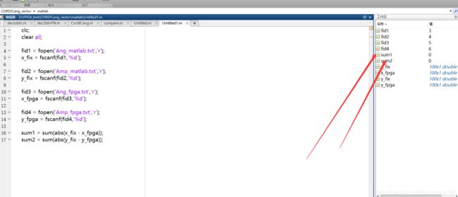
从上面实验验证了我们实验的正确性。
总结
创作不易,认为文章有帮助的同学们可以关注、点赞、转发支持。为行业贡献及其微小的一部分。或者对文章有什么看法或者需要更近一步交流的同学,可以加入下面的群:
