zynq-7z035实现PS对PL端的BRAM的读写实验
0、参考资料
原子哥网站的一些教学pdf
1、实验任务
通过PS的串口,向PS发送数据,PS将收到的数据给PL并且写入到BRAM中,然后同时,也能够读取BRAM中的数据返回到串口中。同时为了,实现ILA的在线的分析的功能,新增加手动的bram 控制模块,对bram 进行读写的控制。
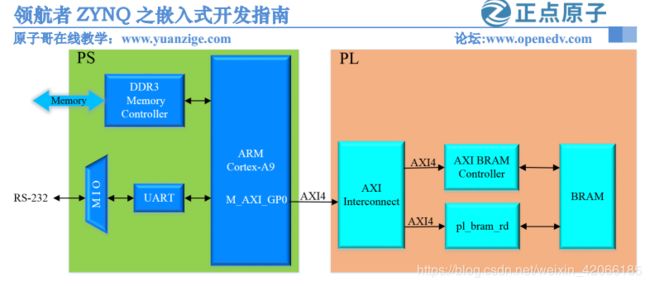
2、实验结构图
具体的接口如下图所示
3、实验过程
3.1 建立vivado工程(示例版本)
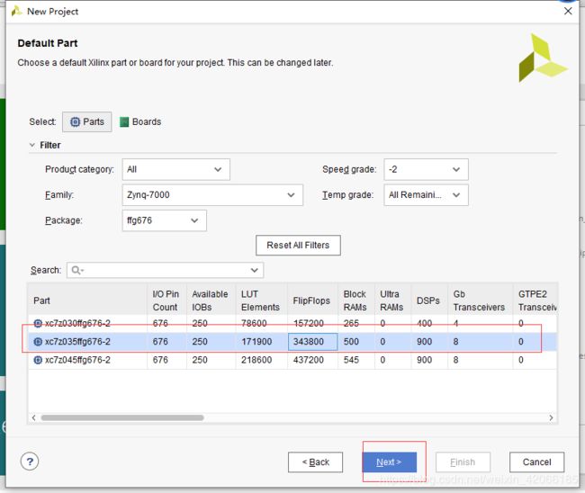
1、建立工程,并且选择对应的器件
2、建立一个ps的处理zynq-配置ddr3 的兼容性,并且增加一个用于调试uart0--使用的是端口14 和 15
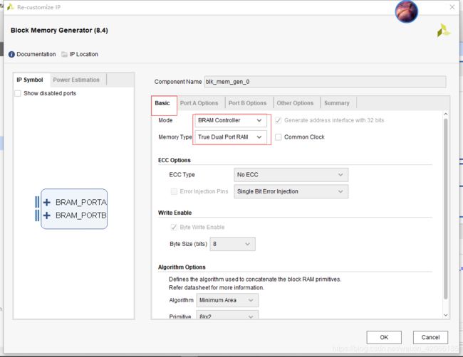
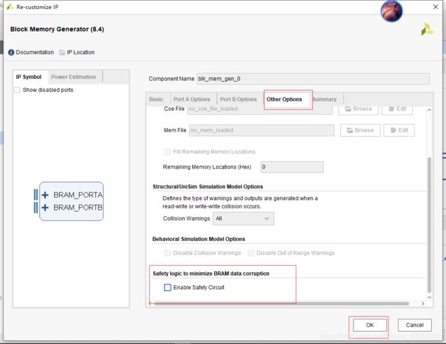
3、增加一个block memory generator 部分,修改basic 和 other options
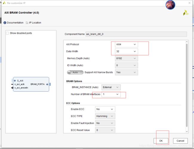
4、增加axi bram controller ,将bram的接口的个数修改成为1个
5、run block autometion。然后连接所有线,为了好看,自动排版。得到如下的架构图
3.2 新建一个读bram的ip
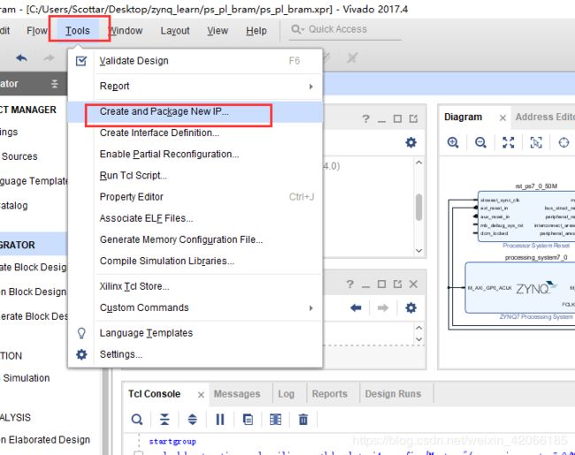
1、新建ip
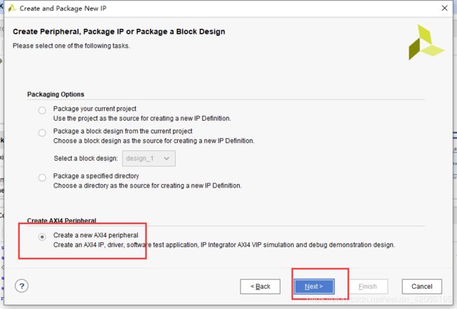
2、选择类型为axi
2、对新建的ip进行编辑
ports 处增加:
		// Users to add ports here
        input      [31:0]  din,
        output     [31:0]  dout,
        output             en,
        output     [3:0]   we,
        output             rst,
        output     [31:0]  addr,
        output             write_end,
在后面的实例化部分增加:
// Instantiation of Axi Bus Interface S00_AXI
	pl_ram_ctrl_v2_0_S00_AXI # (
		.C_S_AXI_DATA_WIDTH(C_S00_AXI_DATA_WIDTH),
		.C_S_AXI_ADDR_WIDTH(C_S00_AXI_ADDR_WIDTH)
	) pl_ram_ctrl_v2_0_S00_AXI_inst (
	    .din         (rdata),
	    .dout        (wdata),
	    .en          (en),
	    .we          (we),
	    .rst         (rst),
	    .addr        (addr),
	    .write_end   (write_end),
最后在其内部的逻辑模块中加入:
	// Add user logic here

	ram_read_write  ram_inst
    (
	 .clk         (S_AXI_ACLK),
	 .rst_n       (S_AXI_ARESETN),

	 .din         (din),
	 .dout        (dout),
	 .en          (en),
	 .we          (we),
	 .rst         (rst),
	 .addr        (addr),
	 .start_clr   (start_clr),
	 .start       (slv_reg0[0]),
	 .init_data   (slv_reg1),
	 .write_end   (write_end),
	 .len         (slv_reg2),
	 .start_addr  (slv_reg3)
	 ) ;
最以后新建一个逻辑功能文件
`timescale 1ns / 1ps
//////////////////////////////////////////////////////////////////////////////////
//                                                                              //
//  Author: myj                                                                 //
//          ALINX(shanghai) Technology Co.,Ltd                                  //
//     WEB: http://www.alinx.cn/                                                //
//                                                                              //
//////////////////////////////////////////////////////////////////////////////////
//                                                                              //
// Copyright (c) 2019,ALINX(shanghai) Technology Co.,Ltd                        //
//                    All rights reserved                                       //
//                                                                              //
// This source file may be used and distributed without restriction provided    //
// that this copyright statement is not removed from the file and that any      //
// derivative work contains the original copyright notice and the associated    //
// disclaimer.                                                                  //
//                                                                              //
//////////////////////////////////////////////////////////////////////////////////

//================================================================================
//   Description:  pl read and write bram
//
//================================================================================
//  Revision History:
//  Date          By            Revision    Change Description
//--------------------------------------------------------------------------------
//  2018/7/27     myj          1.0         Original
//  2019/2/28     myj          2.0         Adding some comments
//********************************************************************************/


module ram_read_write
    (
	 input              clk,
	 input              rst_n,
	 //bram port
     input      [31:0]  din,
	 output reg [31:0]  dout,
	 output reg         en,
	 output reg [3:0]   we,
	 output             rst,
	 output reg [31:0]  addr,
	 //control signal
	 input              start,       //start to read and write bram
	 input      [31:0]  init_data,   //initial data defined by software
	 output reg         start_clr,   //clear start register
	 output reg         write_end,   //write bram completed
	 input      [31:0]  len,         //data count
	 input      [31:0]  start_addr   //start bram address
    );


assign rst = 1'b0 ;

localparam IDLE      = 3'd0 ;
localparam READ_RAM  = 3'd1 ;
localparam READ_END  = 3'd2 ;
localparam WRITE_RAM = 3'd3 ;
localparam WRITE_END = 3'd4 ;

reg [2:0] state ;
reg [31:0] len_tmp ;
reg [31:0] start_addr_tmp ;


always @(posedge clk or negedge rst_n)
begin
  if (~rst_n)
  begin
    state      <= IDLE  ;       //  状态控制信号
	dout       <= 32'd0 ;      // ram 的数据输出信号
	en         <= 1'b0  ;      // ram  是能信号
	we         <= 4'd0  ;      // 读写控制信号
	addr       <= 32'd0 ;      //adddr
	write_end  <= 1'b0  ;      // 写结束标志
	start_clr  <= 1'b0  ;    // 清除开始
	len_tmp    <= 32'd0 ;     //临时长度
	start_addr_tmp <= 32'd0 ; //默认状态为0
  end

  else
  begin
    case(state)
	IDLE            : begin        // 如果是空闲状态,就把其切换到read ram 的情况下
			            if (start)
						begin
			              state <= READ_RAM     ;
						  addr  <= start_addr   ;  // 将地址给的信息给第地址
						  start_addr_tmp <= start_addr ; // 将开始地址给 起始地址
						  len_tmp <= len ;           // 长度
						  dout <= init_data ;       // 将软件的最开始的初始数据,给dout
						  en    <= 1'b1 ;          // 使能
						  start_clr <= 1'b1 ;     //  清除start 为1
						end
				        write_end <= 1'b0 ;    // 写完成的标志
			          end


    READ_RAM        : begin
	                    if ((addr - start_addr_tmp) == len_tmp - 4)      //read completed  // 如果临时的长度-4 == addr -
						begin
						  state <= READ_END ;
						  en    <= 1'b0     ;
						end
						else
						begin
						  addr <= addr + 32'd4 ;				  // address is byte based, for 32bit data width, adding 4
						end
						start_clr <= 1'b0 ;                      // 开始清除,不开始
					  end

    READ_END        : begin
	                    addr  <= start_addr_tmp ;   // 读结束
	                    en <= 1'b1 ;               // 使能
                        we <= 4'hf ;               // 读写使能控制。
					    state <= WRITE_RAM  ;		// 读结束结束之后,将状态切换到write_ram
					  end

	WRITE_RAM       : begin
	                    if ((addr - start_addr_tmp) == len_tmp - 4)   //write completed
						begin
						  state <= WRITE_END ;    // 写结束了,
						  dout  <= 32'd0 ;      // data out
						  en    <= 1'b0  ;    //使能为0
						  we    <= 4'd0  ;    // 读写控制
						end
						else
						begin
						  addr <= addr + 32'd4 ;  // 如果正在写,就把地址每次加4
						  dout <= dout + 32'd1 ; // 将输出的数值,增加1
						end
					  end

	WRITE_END       : begin
	                    addr <= 32'd0 ;     // 将当前的地址变为0
						write_end <= 1'b1 ; // 将 写完成的标志变成1
					    state <= IDLE ;  //将状态切换成idle 状态
					  end
	default         : state <= IDLE ;
	endcase
  end
end

endmodule
以上也就是实际觉得ip的核模块
3、ip-xadc进行操作
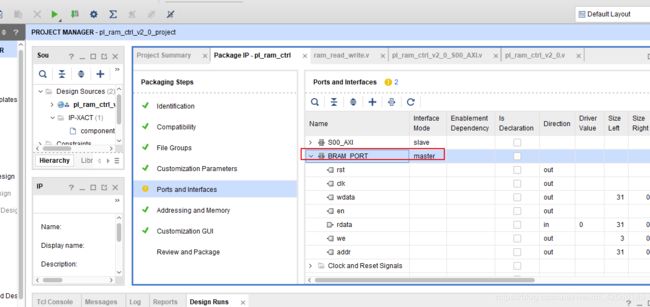
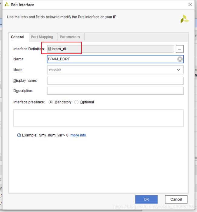
增加这个借口:
双击之后变成:
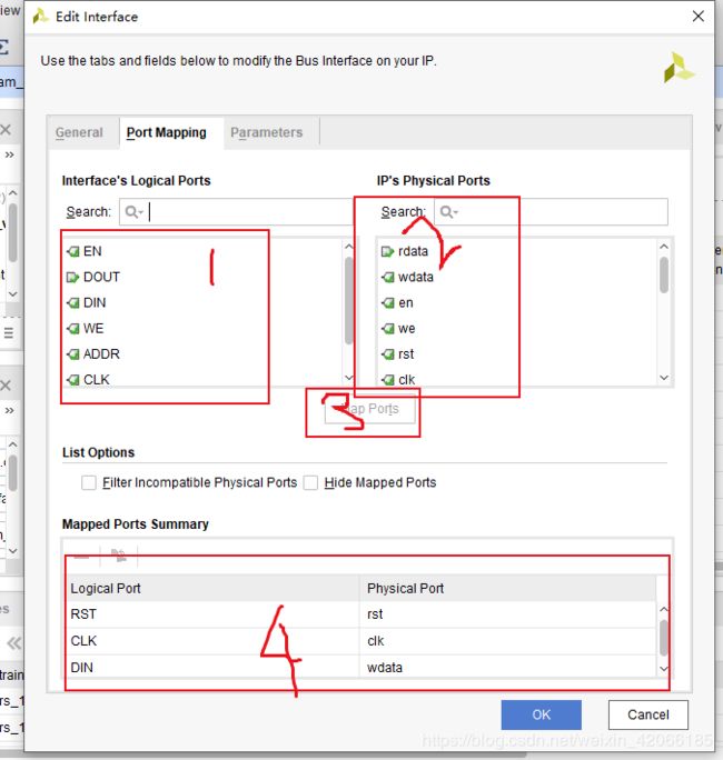
将 端口进行一定的对应
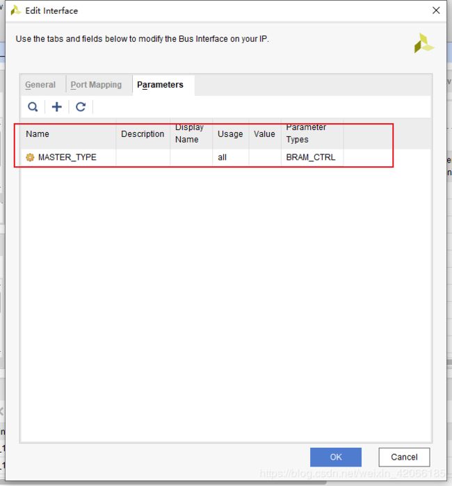
对parameter页进行控制:
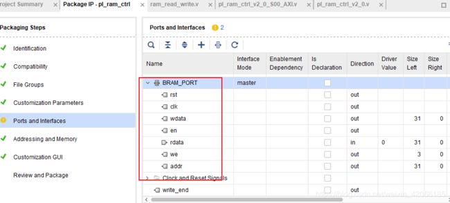
最后的结果:
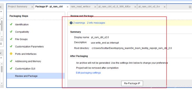
4、最后对该ip进行打包
