基于VHDL语言分频器电路程序设计
基于VHDL语言分频器电路程序设计(汇总)
分频器简介:
分频器是数字电路中最常用的电路之一,在 FPGA 的设计中也是使用效率非常高的基本设计。基于 FPGA 实现的分频电路一般有两种方法:一是使用FPGA 芯片内部提供的锁相环电路,如 ALTERA 提供的 PLL(Phase Locked
Loop),Xilinx 提供的 DLL(Delay Locked Loop);二是使用硬件描述语言,如VHDL、Verilog HDL 等。使用锁相环电路有许多优点,如可以实现倍频;相位偏移;占空比可调等。但 FPGA 提供的锁相环个数极为有限,不能满足使用要求。因此使用硬件描述语言实现分频电路经常使用在数字电路设计中,消耗不多的逻辑单元就可以实现对时钟的操作,具有成本低、可编程等优点。
计数器
计数器是实现分频电路的基础,计数器有普通计数器和约翰逊计数器两种。这两种计数器均可应用在分频电路中。
- 普通计数器: 最普通的计数器是加法(或减法)计数器。
- 约翰逊计数器: 约翰逊计数器是一种移位计数器,采用的是把输出的最高位取非,然后反馈送到最低位触发器的输入端。约翰逊计数器在每个时钟下只有一个输出发生变化。
分频器
如前所述,分频器的基础是计数器,设计分频器的关键在于输出电平翻转的时机。下面使用加法计数器分别描述各种分频器的实现。
- 偶数分频器:偶数分频最易于实现,欲实现占空比为 50%的偶数 N 分频,一般来说有两种方案:一是当计数器计数到N/2-1 时,将输出电平进行一次翻转,同时给计数器一个复位信号,如此循环下去;二是当计数器输出为 0 到 N/2-1 时,时钟输出为 0 或 1,计数器输出为 N/2 到 N-1 时,时钟输出为 1 或 0,当计数器计数到N-1 时,复位计数器,如此循环下去。需要说明的是,第一种方案仅仅能实现占空比为 50%的分频器,第二种方案可以有限度的调整占空比,参考非 50%占空比的奇数分频实现。
- 奇数分频器:实现非50%占空比的奇数分频,如实现占空比为 20%(1/5)、40%(2/5)、60%(3/5)、80%(4/5)的 5 分频器,可以采用似偶数分频的第二种方案;但如果实现占空比为 50%的奇数分频,就不能使用偶数分频中所采用的方案了。
- 半整数分频器:仅仅采用数字分频,不可能获得占空比为 50%的 N+0.5 分频,我们只可以设计出占空比为(M+0.5)/(N+0.5)或者 M/(N+0.5)的分频器,M 小于 N。这种半整数分频方法是对输入时钟进行操作,让计数器计数到某一个数值时,将输入时钟电平进行一次反转,这样,该计数值只保持了半个时钟周期,因此实现半整数分频。
- 小数分频器:小数分频是通过可变分频和多次平均的方法实现的。例如要实现 4.7 分频,只要在 10 次分频中,做 7 次 5 分频,3 次 4 分频就可以得到。再如要实现 5.67 分频,只要在 100 次分频中,做 67 次6 分频,33 次 5 分频即可。考虑到小数分频器要进行多次两种频率的分频,必须设法将两种分频均匀。
- 分数分频器:将小数分频的方法进行扩展,可以得到形如M (L/N )的分数分频的方法,例如, 2(7/13)等于分母的,进行分频,只要在 13 次分频中,进行 7 次 3 分频,6 次 2 分频就可以得到。同样,为了将两种分频均匀,将分子部分累加,小于分母的,进行M分频,大于(M+1)分频。
- 积分分频器:积分分频器用于实现形如 2 m − 1 / N 2^{m-1}/N 2m−1/N的分频,例如 8/3 分频。我们当然可以使用上面提到的分数分频的方法,但对于这种形式的分频,使用积分分频的方法综合往往占用更少的 FPGA 资源。积分分频法基于下述原理:一个 m 位的二进制数字每次累加 N,假定累加x 次累加值最低m 位回到 0,同时越过 2 m y 2^my 2my 次,那么,当前累加的数字应该是Nx= 2 m y 2^my 2my;每越过 2 m 2^m 2m一次,最高位变化 2 次,所以,累加 x 次,最高位变化 2y次,得到 x / 2 y = 2 m − 1 / N x/2y=2^{m-1}/N x/2y=2m−1/N分频的分频器例如,取 m 为 4,N 为 3,当累加 16 次时,累加值为 48,最低 m 位变回到 0,同时越过 16 三次,最高位变化 6 次,由此得到 16/6=8/3 分频的分频器。
注意: 以上分频器程序设计的案例将会在下边进行一一分析。
软件说明: ModelSimSetup-13.1.0.162,QuartusSetup-13.1.0.162。
建立工程:
第一步:打开Quartus软件。
第二步:点击New Project Wizard -> next.
第三步:选择工程文件的存放位置,输入工程名 -> next -> next。
第四步:在family栏选择芯片型号-Cyclone IV E,在Name栏选择EP4CE115F29C7,选择完之后点击next。(如果不进行硬件调试时,此处默认即可)
第五步:检查工程有没有建错,点击完成。如下图:
程序设计:
普通计数器:
--文件名:ADDER8B.vhd 应与工程名保持一致:
--Description: 带复位功能的加法计数器
library ieee;
use ieee.std_logic_1164.all;
use ieee.std_logic_arith.all;
use ieee.std_logic_unsigned.all;
entity ripple is
 generic (width: integer := 4);
 port(clk, rst: in std_logic;
 cnt: out std_logic_vector(width - 1 downto 0));
end ripple;
architecture a of ripple is
 signal cntQ: std_logic_vector(width - 1 downto 0);
begin
	 process(clk, rst)
	 begin
	 if (rst = '1') then
		 cntQ <= (others => '0');
	 elsif (clk'event and clk = '1') then
		 cntQ <= cntQ + 1;
	 end if;
	 end process;
 cnt <= cntQ;
end a;
在同一时刻,加法计数器的输出可能有多位发生变化,因此,当使用组合逻辑对输出进行译码时,会导致尖峰脉冲信号。使用约翰逊计数器可以避免这个问题。
文件仿真(这里采用modelsim仿真波形):
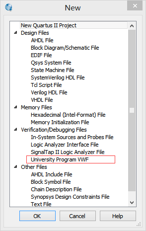
- 选择File-> New -> Verification/Debugging Files ->University Program VWF。
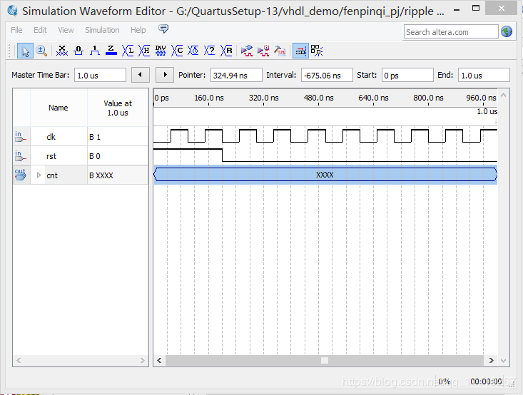
2.打开测试文件。(右键点击添加端口,对输入信号初始化,赋值。)
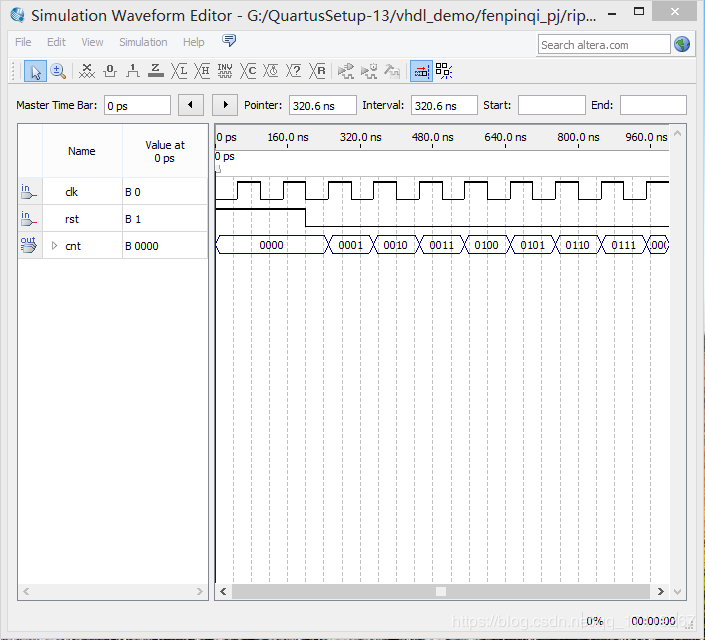
3.仿真结果:
逻辑电路图:
约翰逊计数器:
--file Name: johnson.vhd
--Description: 带复位功能的约翰逊计数器
library ieee;
use ieee.std_logic_1164.all;
use ieee.std_logic_arith.all;
use ieee.std_logic_unsigned.all;
entity johnson is
 generic (width: integer := 4);
 port (clk, rst: in std_logic;
 cnt: out std_logic_vector(width - 1 downto 0));
end johnson;
architecture a of johnson is
 signal cntQ: std_logic_vector(width - 1 downto 0);
begin
 process(clk, rst)
 begin
 if(rst = '1') then
 cntQ <= (others => '0');
 elsif (rising_edge(clk)) then
 cntQ(width - 1 downto 1) <= cntQ(width - 2 downto 0);
 cntQ(0) <= not cntQ(width - 1);
 end if;
 end process;
   cnt <= cntQ;
end a;
逻辑电路图:
仿真结果:
显然,约翰逊计数器没有有效利用寄存器的所有状态,假设最初值或复位状态为0000,则依次为 0000、0001、0011、0111、1111、1110、1100、1000、0000 如 循环。再者,如果由于干扰噪声引入一个无效状态,如 0010,则无法恢复到有效到循环中去,需要我们加入错误恢复处理.
偶数分频器:(6 分频)
architecture a 使用的是第一种方案,architecture b 使用的是第二种方案。更改 configuration 可查看不同方案的综合结果。
--filename clk_div6.vhd
--description: 占空比为 50%的 6 分频
library ieee;
use ieee.std_logic_1164.all;
use ieee.std_logic_arith.all;
use ieee.std_logic_unsigned.all;
entity clk_div6 is
 port(clk_in: in std_logic; clk_out: out std_logic);
end clk_div6;
--使用第一种方案
architecture a of clk_div6 is
	 signal clk_outQ: std_logic := '0';--赋初始值仅供仿真使用
	 signal countQ: std_logic_vector(2 downto 0) := "000";
	 begin
		 process(clk_in)
		 begin
		 if(clk_in'event and clk_in = '1') then
			 if(countQ /= 2) then
				 CountQ <= CountQ + 1;
			 else
				 clk_outQ <= not clk_outQ;
				 CountQ <= (others =>'0');
			 end if;
		 end if;
		 end process;
	 clk_out <= clk_outQ;
end a;
--使用第二种方案
architecture b of clk_div6 is
	 signal countQ: std_logic_vector(2 downto 0);
	 begin
		 process(clk_in)
		 begin
			 if(clk_in'event and clk_in = '1') then
				 if(countQ < 5) then
					 countQ <= countQ + 1;
				 else
					 CountQ <= (others =>'0');
				 end if;
			 end if;
		 end process;
		 process(countQ)
		 begin
				 if(countQ < 3) then
					 clk_out <= '0';
				 else
					 clk_out <= '1';
				end if;
		 end process;
 end b;

configuration cfg of clk_div6 is
 for a
 end for;
end cfg;
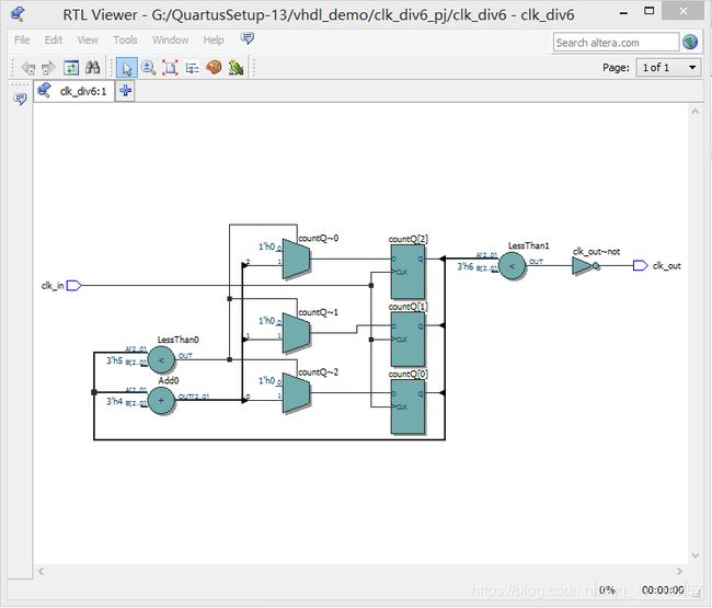
逻辑电路图:
architecture a:
architecture b:
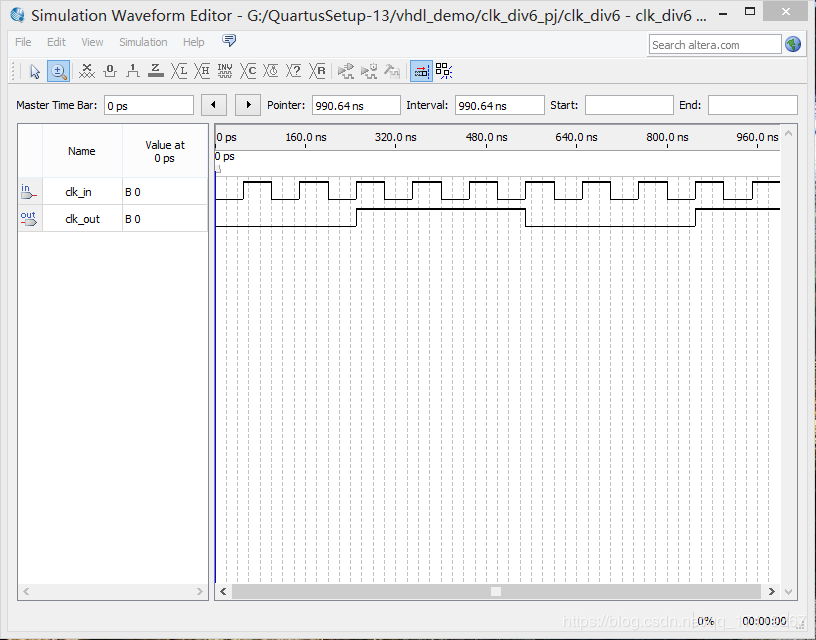
仿真结果:
architecture a、b:
奇数分频器:
非 50%占空比:
下面就以实现占空比为40%的 5 分频分频器为例,说明非 50%占空比的奇数分频器的实现。该分频器的实现对于我们实现 50%占空比的分频器有一定的借鉴意义。
--filename clk_div5.vhd
--description: 占空比为 40%的 5 分频
library ieee;
use ieee.std_logic_1164.all;
use ieee.std_logic_arith.all;
use ieee.std_logic_unsigned.all;
entity clk_div5 is
 port(clk_in: in std_logic; clk_out: out std_logic);
end clk_div5;
architecture a of clk_div5 is
   signal countQ: std_logic_vector(2 downto 0);
	begin
	 process(clk_in)
	 begin
		if(clk_in'event and clk_in = '1') then
			if(countQ < 4) then
				 countQ <= countQ + 1;
			 else
				 CountQ <= (others =>'0');
			 end if;
		end if;
	 end process;
		process(countQ)
		 begin
			 if(countQ < 3) then
				 clk_out <= '0';
			 else
				 clk_out <= '1';
			 end if;
	 end process;
end a;
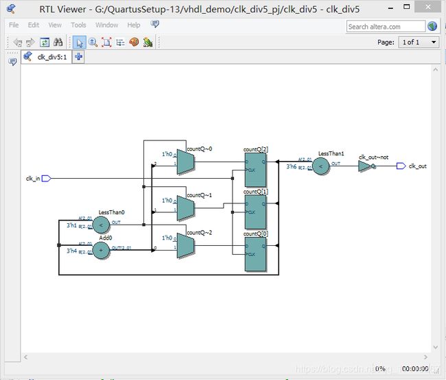
逻辑电路图:
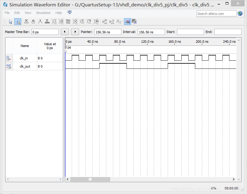
仿真结果:
50%占空比的奇数分频:
通过待分频时钟下降沿触发计数,产生一个占空比为40%(2/5)的 5 分频器。将产生的时钟与上升沿触发产生的时钟相或,即可得到一个占空比 50%的 5 分频器。
推广为一般方法:欲实现占空比为 50%的 2N+1 分频器,则需要对待分频时钟上升沿和下降沿分别进行N/(2N+1)分频,然后将两个分频所得的时钟信号相或得到占空比为 50%的 2N+1 分频器。
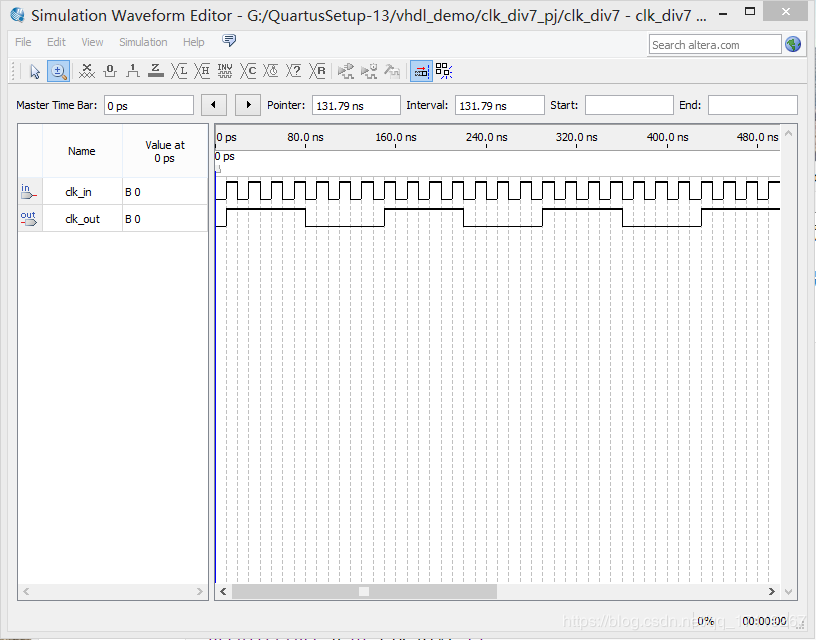
下面的代码就是利用上述思想获得占空比为 50%的 7 分频器。需要我们分别对上升沿和下降沿进行 3/7 分频,再将分频获得的信号相或。
--filename clk_div7.vhd
--description: 占空比为 50%的 7 分频
library ieee;
use ieee.std_logic_1164.all;
use ieee.std_logic_arith.all;
use ieee.std_logic_unsigned.all;
entity clk_div7 is
	port(clk_in: in std_logic; clk_out: out std_logic);
end clk_div7;

architecture a of clk_div7 is
	 signal cnt1, cnt2: integer range 0 to 6;
	 signal clk1,clk2: std_logic;
	 begin
		 process(clk_in)--上升沿
			begin
			 if(rising_edge(clk_in)) then
				 if(cnt1 < 6)then
					cnt1 <= cnt1 + 1;
				 else
				   cnt1 <= 0;
				 end if;
				 if(cnt1 < 3) then
					 clk1 <= '1';
				 else
					clk1 <= '0';
				 end if;
			 end if;
		 end process;
		 process(clk_in)--下降沿
			begin
				 if(falling_edge(clk_in)) then
					if(cnt2 < 6) then
						 cnt2 <= cnt2 + 1;
					 else
						 cnt2 <= 0;
					 end if;
					 if(cnt2 < 3) then
						 clk2 <= '1';
					 else
						 clk2 <= '0';
					 end if;
				  end if;
		 end process;
	clk_out <= clk1 or clk2;
end a;
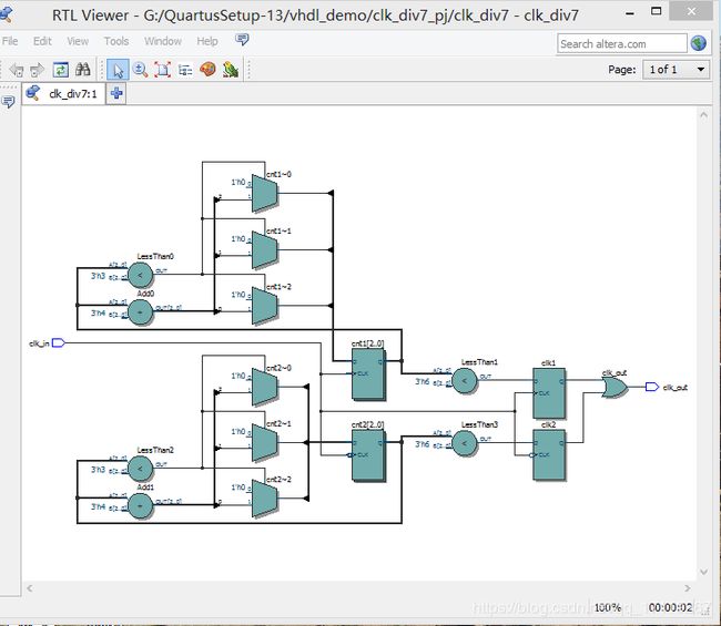
逻辑电路图:
仿真结果:
半整数分频器:
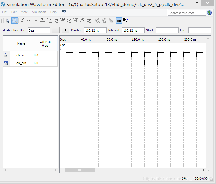
如上所述,占空比为 50%的奇数分频可以帮助我们实现半整数分频,将占空比为50%的奇数分频与待分频时钟异或得到计数脉冲,下面的代码就是依靠占空比为 50%的 5 分频实现 2.5 分频器的。
--filename clk_div2_5.vhd
--description: 占空比为 1/1.5,即 60%。的 2.5分频
library ieee;
use ieee.std_logic_1164.all;
use ieee.std_logic_arith.all;
use ieee.std_logic_unsigned.all;

entity clk_div2_5 is
	  port(clk_in: in std_logic; clk_out: out std_logic);
end clk_div2_5;

architecture a of clk_div2_5 is
  signal cnt1, cnt2: integer range 0 to 4;
  signal clk1, clk2: std_logic;
  signal Pclk, Lclk: std_logic;
  signal cnt3:integer range 0 to 2;
begin
	 process(clk_in)
		 begin
			 if(rising_edge(clk_in)) then
				 if(cnt1 < 4) then
					 cnt1 <= cnt1 + 1;
				 else
					 cnt1 <= 0;
				 end if;
			 end if;
	 end process;
	 process(clk_in)
		 begin
			 if(falling_edge(clk_in)) then
					if(cnt2 <4)  then
						 cnt2 <= cnt2 + 1;
					else
						 cnt2 <= 0;
					end if;
			 end if;
	 end process;
	 process(cnt1)
		 begin
			 if (cnt1 <3) then
				clk1 <= '0';
			 else
				 clk1 <= '1';
			 end if;
	 end process;
	 process(cnt2)
		 begin
			 if (cnt2 < 3) then
				 clk2 <= '0';
			 else
				 clk2 <= '1';
			 end if;
	 end process;

	 process(Lclk)
	 begin
		if(rising_edge(Lclk)) then
			 if(cnt3 < 2) then
				cnt3 <= cnt3 + 1;
		    else
			   cnt3 <= 0;
		    end if;
		end if;
	 end process;
	 process(cnt3)
		 begin
		 if(cnt3 < 2) then
			 clk_out <= '0';
		 else
			 clk_out <='1';
		 end if;
	 end process;
	 Pclk <= clk1 or clk2;
	 Lclk <= clk_in xor Pclk;--对输入时钟进行处理
end a;
仿真结果:
小数分频器:
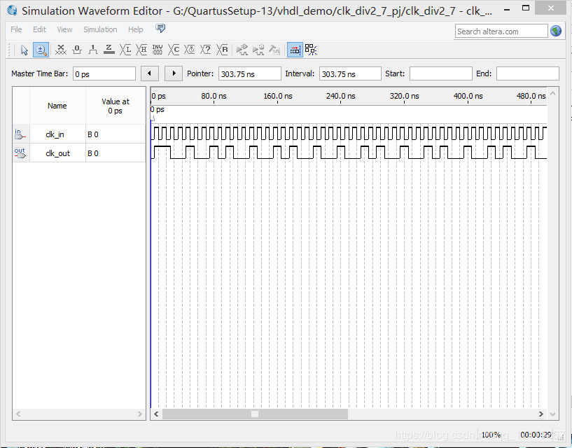
表 1以 2.7 分频为例,小数部分进行累加,如果大于等于10,则进行 3 分频,如果小于 10,进行
2 分频。
表一:小数分频系数序列
| 序号 | 0 | 1 | 2 | 3 | 4 | 5 | 6 | 7 | 8 | 9 |
|---|---|---|---|---|---|---|---|---|---|---|
| 累加值 | 7 | 14 | 11 | 8 | 15 | 12 | 9 | 16 | 13 | 10 |
| 分频 系数 | 2 | 3 | 3 | 2 | 3 | 3 | 2 | 3 | 3 | 3 |
下加器面的代码就是基于上述原理实现 2.7 分频。architecture b 是使用累加器计算分频系数选则时机, chitectur a 是直接使用已计算好的结果。
--file name: clk_div2_7.vhd
--description: 2.7 分频 ,占空比应为 10/27。
library ieee;
use ieee.std_logic_1164.all;
use ieee.std_logic_arith.all;
use ieee.std_logic_unsigned.all;
entity clk_div2_7 is
	  port(clk_in: in std_logic; clk_out: out std_logic);
end clk_div2_7;
architecture b of clk_div2_7 is
 signal clkoutQ: std_logic;
 signal ctrl: std_logic;
 signal cnt1: integer range 0  to 1;
 signal cnt2: integer range 0  to 2;
begin
	 clk_out <= clkoutQ;
	 process(clkoutQ)
		variable tmp: integer range 0 to 20;
		begin
			 if(rising_edge(clkoutQ)) then
					tmp := tmp + 7;
				 if(tmp < 10) then
						ctrl <= '1';
				 else
						ctrl <= '0';
						tmp := tmp - 10;
				 end if;
			 end if;
	 end process;

	 process(clk_in)
		 begin
			 if(clk_in'event and clk_in = '1') then
				 if(ctrl = '1') then
					 if(cnt1 < 1) then
						  cnt1 <= cnt1 + 1;
					 else
						  cnt1 <= 0;
					 end if;
					 if(cnt1 < 1) then
					     clkoutQ <= '1';
					 else
						  clkoutQ <= '0';
					 end if;
				 else
					 if(cnt2 < 2) then
							cnt2 <= cnt2 + 1;
					 else
							cnt2 <= 0;
					 end if;
				 if(cnt2 < 1) then
					 clkoutQ <= '1';
				 else
					 clkoutQ <= '0';
				 end if;
				 end if;
			  end if;
	 end process;
 end b;
 architecture a of clk_div2_7 is
	 signal cnt: integer range 0 to 9;
	 signal clkoutQ: std_logic;
	 signal cnt1: integer range 0 to 1;
	 signal cnt2: integer range 0 to 2;
	begin
		clk_out <= clkoutQ;
		process(clkOutQ)
		  begin
			 if(clkoutQ'event and clkoutQ = '1') then
					if (cnt < 9) then
					    cnt <= cnt + 1;
					else
					    cnt <= 0;
					end if;
			 end if;
		end process;
		process(clk_in)
		  begin
			 if(clk_in'event and clk_in = '1') then
				 case cnt is
					  when 0|3|6 =>
						  if(cnt1 < 1) then
							   cnt1 <= cnt1 + 1;
						  else
							   cnt1 <= 0;
						  end if;
						  if(cnt1 < 1) then
								clkoutQ <= '1';
						  else
								clkoutQ <='0';
						  end if;
					  when others =>
						  if(cnt2 < 2) then
							  cnt2 <= cnt2 + 1;
						  else
						     cnt2 <= 0;
						 end if;
						 if(cnt2 < 1) then
						     clkoutQ <= '1';
						 else
						     clkoutQ <= '0';
						 end if;
				 end case;
			 end if;
		 end process;
 end a;

configuration cfg of clk_div2_7 is
	 for a
	 end for;
end cfg;
仿真结果:
分数分频器:
表 2显示了 2(7/13)的分频次序。仿照小数分频器代码,给出 2(7/13) 分频的代码如下:
表 2 分数分频系数序列
| 序号 | 0 | 1 | 2 | 3 | 4 | 5 | 6 | 7 | 8 | 9 | 10 | 11 | 12 |
|---|---|---|---|---|---|---|---|---|---|---|---|---|---|
| 累加值 | 7 | 14 | 8 | 15 | 9 | 16 | 10 | 17 | 11 | 18 | 12 | 19 | 13 |
| 分频 系数 | 2 | 3 | 2 | 3 | 2 | 3 | 2 | 3 | 2 | 3 | 2 | 3 | 3 |
--file name: clk_div2_7_13.vhd
--description: 33/13分频
library ieee;
use ieee.std_logic_1164.all;
use ieee.std_logic_arith.all;
use ieee.std_logic_unsigned.all;
entity clk_div2_7 is
	  port(clk_in: in std_logic; clk_out: out std_logic);
end clk_div2_7;
architecture b of clk_div2_7 is
 signal clkoutQ: std_logic;
 signal ctrl: std_logic;
 signal cnt1: integer range 0  to 1;
 signal cnt2: integer range 0  to 2;
begin
	 clk_out <= clkoutQ;
	 process(clkoutQ)
		variable tmp: integer range 0 to 26;
		begin
			 if(rising_edge(clkoutQ)) then
					tmp := tmp + 7;
				 if(tmp < 10) then
						ctrl <= '1';
				 else
						ctrl <= '0';
						tmp := tmp - 13;
				 end if;
			 end if;
	 end process;

	 process(clk_in)
		 begin
			 if(clk_in'event and clk_in = '1') then
				 if(ctrl = '1') then
					 if(cnt1 < 1) then
						  cnt1 <= cnt1 + 1;
					 else
						  cnt1 <= 0;
					 end if;
					 if(cnt1 < 1) then
					     clkoutQ <= '1';
					 else
						  clkoutQ <= '0';
					 end if;
				 else
					 if(cnt2 < 2) then
							cnt2 <= cnt2 + 1;
					 else
							cnt2 <= 0;
					 end if;
				 if(cnt2 < 1) then
					 clkoutQ <= '1';
				 else
					 clkoutQ <= '0';
				 end if;
				 end if;
			  end if;
	 end process;
 end b;
 architecture a of clk_div2_7 is
	 signal cnt: integer range 0 to 12;
	 signal clkoutQ: std_logic;
	 signal cnt1: integer range 0 to 1;
	 signal cnt2: integer range 0 to 2;
	begin
		clk_out <= clkoutQ;
		process(clkOutQ)
		  begin
			 if(clkoutQ'event and clkoutQ = '1') then
					if (cnt < 9) then
					    cnt <= cnt + 1;
					else
					    cnt <= 0;
					end if;
			 end if;
		end process;
		process(clk_in)
		  begin
			 if(clk_in'event and clk_in = '1') then
				 case cnt is
					  when 0|2|4|6|8|10 =>
						  if(cnt1 < 1) then
							   cnt1 <= cnt1 + 1;
						  else
							   cnt1 <= 0;
						  end if;
						  if(cnt1 < 1) then
								clkoutQ <= '1';
						  else
								clkoutQ <='0';
						  end if;
					  when others =>
						  if(cnt2 < 2) then
							  cnt2 <= cnt2 + 1;
						  else
						     cnt2 <= 0;
						 end if;
						 if(cnt2 < 1) then
						     clkoutQ <= '1';
						 else
						     clkoutQ <= '0';
						 end if;
				 end case;
			 end if;
		 end process;
 end a;

configuration cfg of clk_div2_7 is
	 for b
	 end for;
end cfg;
仿真结果:
积分分频器:
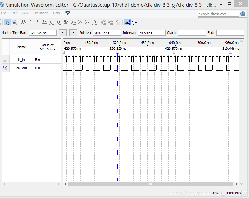
例如,取 m 为 4,N 为 3,当累加 16 次时,累加值为 48,最低 m 位变回到 0,同时越过 16 三次,最高位变化 6 次,由此得到 16/6=8/3 分频的分频器。
--file name: clk_div8.vhd
--description: 使用积分分频实现 8/3 分频
library ieee;
use ieee.std_logic_1164.all;
use ieee.std_logic_unsigned.all;
entity clk_div_8f3 is
  port(clk_in: in std_logic; clk_out: out std_logic);
end clk_div_8f3;
architecture a of clk_div_8f3 is
	  signal cnt: std_logic_vector(3 downto 0) := (others => '0');
	  signal dly: std_logic;
	  begin
		 process(clk_in)
		  begin
		 if(clk_in'event and clk_in = '1') then
				 dly <= cnt(3);
				 cnt <= cnt + 3;
		  end if;
		 end process;
	  clk_out <= dly xor cnt(3);
 end a;
仿真结果:

