ORB-SLAM2代码阅读笔记(三):Tracking线程1——进入Tracking线程
Table of Contents
1.Tracking线程主要工作
2.Tracking构造函数代码解析
3.Tracking线程中调用的第一个函数Tracking::GrabImageMonocular
4.Frame.cc中的单目Frame构造函数代码解析
5.本篇笔记的结构图总结
在上一篇 ORB-SLAM2代码阅读笔记(二):System.cc相关函数 的基础上,接下来分析Tracking线程。
1.Tracking线程主要工作
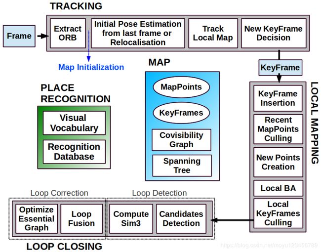
从以上ORB-SLAM2的系统框架图可以看出,Tracking线程的输入为图片帧,然后根据输入的Frame来进行四个步骤:
1)ORB特征提取;
2)从上一帧进行初始化位姿估计或者进行重定位;
3)跟踪局部地图;
4)新的关键帧生成。
Tracking线程的输出为新生成的关键帧,并将新生成的关键帧传给LocalMapping线程继续后边的工作。
2.Tracking构造函数代码解析
Tracking的构造函数主要是从设置文件中读取预先配置的数据,为之后线程工作做准备,主要有以下5部分:
1)从配置文件中读取相机内参数据,并生成相机内参矩阵;
2)从配置文件中读取去畸变参数,并生成去畸变矩阵。去畸变一般都是针对鱼眼图像来进行的,mono_kitti数据没有发生畸变,所以这里的去畸变参数都是0,也就是说不需要进行去畸变操作;
3)从配置文件中读取图片的颜色序列;
4)从配置文件中读取金字塔图像提取器的参数,供生成图像金字塔时使用。这里说的图像金字塔,是指对原始的一帧图像经过等比例缩放所产生的一系列图像放在一起构成的金字塔模型。比如一个8层的缩放因子为0.9的金字塔图像模型是这么生成的:将原始图像等比例进行0.9倍的缩放,得到第一层的图像;对第一层的图像再进行0.9倍的缩放,得到第二层的图像....依次生成7层图像,和原始图像合在一起就构成了8层的金字塔图像模型。
5)创建特征提取器,为后边提取图像特征做好准备。
Tracking::Tracking(System *pSys, ORBVocabulary* pVoc, FrameDrawer *pFrameDrawer, MapDrawer *pMapDrawer, Map *pMap, KeyFrameDatabase* pKFDB, const string &strSettingPath, const int sensor):
    mState(NO_IMAGES_YET), mSensor(sensor), mbOnlyTracking(false), mbVO(false), mpORBVocabulary(pVoc),
    mpKeyFrameDB(pKFDB), mpInitializer(static_cast(NULL)), mpSystem(pSys), mpViewer(NULL),
    mpFrameDrawer(pFrameDrawer), mpMapDrawer(pMapDrawer), mpMap(pMap), mnLastRelocFrameId(0)
{
    // Load camera parameters from settings file

    cv::FileStorage fSettings(strSettingPath, cv::FileStorage::READ);
    float fx = fSettings["Camera.fx"];
    float fy = fSettings["Camera.fy"];
    float cx = fSettings["Camera.cx"];
    float cy = fSettings["Camera.cy"];
    /**
     * 1.构造相机内参矩阵
     * | fx 0  cx |
     * | 0  fy cy |
     * | 0  0  1  |
    */
    cv::Mat K = cv::Mat::eye(3,3,CV_32F);//创建了3*3的矩阵,元素使用32位单精度浮点型
    K.at(0,0) = fx;
    K.at(1,1) = fy;
    K.at(0,2) = cx;
    K.at(1,2) = cy;
    K.copyTo(mK);//mK中存放的是相机的内参矩阵
    //2.创建了4*1的矩阵,用于存放相机去畸变的参数。mono_kitti不需要去畸变,所以这些参数都为0
    cv::Mat DistCoef(4,1,CV_32F);
    DistCoef.at(0) = fSettings["Camera.k1"];
    DistCoef.at(1) = fSettings["Camera.k2"];
    DistCoef.at(2) = fSettings["Camera.p1"];
    DistCoef.at(3) = fSettings["Camera.p2"];
    const float k3 = fSettings["Camera.k3"];
    if(k3!=0)
    {
        DistCoef.resize(5);
        DistCoef.at(4) = k3;
    }
    DistCoef.copyTo(mDistCoef);//mDistCoef中存放的是相机图片去畸变的参数

    mbf = fSettings["Camera.bf"];
    //Camera frames per second
    float fps = fSettings["Camera.fps"];
    if(fps==0)//从配置文件中读取的fps=10.0
        fps=30;

    // Max/Min Frames to insert keyframes and to check relocalisation
    mMinFrames = 0;
    mMaxFrames = fps;

    cout << endl << "Camera Parameters: " << endl;
    cout << "- fx: " << fx << endl;
    cout << "- fy: " << fy << endl;
    cout << "- cx: " << cx << endl;
    cout << "- cy: " << cy << endl;
    cout << "- k1: " << DistCoef.at(0) << endl;
    cout << "- k2: " << DistCoef.at(1) << endl;
    if(DistCoef.rows==5)
        cout << "- k3: " << DistCoef.at(4) << endl;
    cout << "- p1: " << DistCoef.at(2) << endl;
    cout << "- p2: " << DistCoef.at(3) << endl;
    cout << "- fps: " << fps << endl;

    //3.读取颜色序列0: BGR, 1: RGB.配置文件中读取的是1
    int nRGB = fSettings["Camera.RGB"];
    mbRGB = nRGB;

    if(mbRGB)
        cout << "- color order: RGB (ignored if grayscale)" << endl;
    else
        cout << "- color order: BGR (ignored if grayscale)" << endl;

    // Load ORB parameters
    //4.加载金字塔图像提取器的参数
    int nFeatures = fSettings["ORBextractor.nFeatures"];//每张图片中提取的ORB特征数(2000)
    float fScaleFactor = fSettings["ORBextractor.scaleFactor"];//ORB Extractor: Scale factor between levels in the scale pyramid(1.2)
    int nLevels = fSettings["ORBextractor.nLevels"];//ORB Extractor: Number of levels in the scale pyramid(8)
    int fIniThFAST = fSettings["ORBextractor.iniThFAST"];//(10)
    int fMinThFAST = fSettings["ORBextractor.minThFAST"];//(5)

    mpORBextractorLeft = new ORBextractor(nFeatures,fScaleFactor,nLevels,fIniThFAST,fMinThFAST);

    if(sensor==System::STEREO)
        mpORBextractorRight = new ORBextractor(nFeatures,fScaleFactor,nLevels,fIniThFAST,fMinThFAST);
    //5.构建特征提取器。单目传入的特征数为其他的2倍,这里是2*2000=4000
    if(sensor==System::MONOCULAR)
        mpIniORBextractor = new ORBextractor(2*nFeatures,fScaleFactor,nLevels,fIniThFAST,fMinThFAST);

    cout << endl  << "ORB Extractor Parameters: " << endl;
    cout << "- Number of Features: " << nFeatures << endl;
    cout << "- Scale Levels: " << nLevels << endl;
    cout << "- Scale Factor: " << fScaleFactor << endl;
    cout << "- Initial Fast Threshold: " << fIniThFAST << endl;
    cout << "- Minimum Fast Threshold: " << fMinThFAST << endl;

    if(sensor==System::STEREO || sensor==System::RGBD)
    {
        mThDepth = mbf*(float)fSettings["ThDepth"]/fx;
        cout << endl << "Depth Threshold (Close/Far Points): " << mThDepth << endl;
    }

    if(sensor==System::RGBD)
    {
        mDepthMapFactor = fSettings["DepthMapFactor"];
        if(fabs(mDepthMapFactor)<1e-5)
            mDepthMapFactor=1;
        else
            mDepthMapFactor = 1.0f/mDepthMapFactor;
    }

}
Tracking构造方法中创建了ORB特征提取器,调用ORBextractor的构造函数代码解析如下:
/**
 * 这个是类ORBextractor的带参构造函数,并且使用初始化列表对该类中的这5个变量赋值
 * ORB特征点提取器
 * nt _nfeatures       特征点个数,单目mono_kitti中该值为4000
 * float _scaleFactor  金字塔中相邻层图像的比例系数,单目mono_kitti中该值为1.2
 * int _nlevels        构造金字塔的层数,单目mono_kitti中该值为8
 * int _iniThFAST      检测FAST角点的阈值,单目mono_kitti中该值为20
 * int _minThFAST      在iniThFAST没有检测到角点的前提下,降低的阈值,单目mono_kitti中该值为7
 *
*/
ORBextractor::ORBextractor(int _nfeatures, float _scaleFactor, int _nlevels,
         int _iniThFAST, int _minThFAST):
    nfeatures(_nfeatures), scaleFactor(_scaleFactor), nlevels(_nlevels),
    iniThFAST(_iniThFAST), minThFAST(_minThFAST)
{
    //mvScaleFactor是用来存储金字塔中每层图像对应的尺度变换因子的vector变量
    mvScaleFactor.resize(nlevels);
    //mvLevelSigma2是该层尺度因子的平方
    mvLevelSigma2.resize(nlevels);
    mvScaleFactor[0]=1.0f;
    mvLevelSigma2[0]=1.0f;
    /**
     * 计算金字塔中每一层图像对应的尺度因子和尺度因子的平方。
     * 金字塔中第0层的尺度因子是1,然后每向上高一层,图像的尺度因子是在上一层图像的尺度因子上乘以scaleFactor,在本工程下该值为1.2
     * 1  1/1.2  1/1.2^2  1/1.2^3  1/1.2^4  1/1.2^5  1/1.2^6  1/1.2^7
    */
    for(int i=1; i pattern里;
    //最后pattern储存了512个Point
    const Point* pattern0 = (const Point*)bit_pattern_31_;
    //复制训练的模板pattern0到pattern中
    std::copy(pattern0, pattern0 + npoints, std::back_inserter(pattern));

    //This is for orientation
    // pre-compute the end of a row in a circular patch
    //这里是为了计算关键点方向的准备工作
    //我们是要在以关键点keypoint像素坐标点为中心的半径为HALF_PATCH_SIZE的patch圆内计算关键点keypoint的方向。
    //怎样描述这个patch圆的范围呢?这里选择的是储存不同v所对应的的umax来描述这个patch圆的范围。
    umax.resize(HALF_PATCH_SIZE + 1);//umax的size大小为16
    //cvFloor():返回不大于参数的最大整数值,即向下取整
    //这里计算得vmax=11
    int v, v0, vmax = cvFloor(HALF_PATCH_SIZE * sqrt(2.f) / 2 + 1);
    //cvCeil():返回不小于参数的最小整数值,即向上取整
    //这里计算得vmin=11
    int vmin = cvCeil(HALF_PATCH_SIZE * sqrt(2.f) / 2);
    //hp2=225
    const double hp2 = HALF_PATCH_SIZE*HALF_PATCH_SIZE;
    //v从0到11依次遍历,umax中存储12个数:15 15 15 15 14 14 14 13 13 12 11 10
    for (v = 0; v <= vmax; ++v)
        umax[v] = cvRound(sqrt(hp2 - v * v));

    // Make sure we are symmetric
    //下面是算当v=vmin至HALF_PATCH_SIZE时的umax[v],那就是v从11到15之间的值
    //计算得umax[15]-umax[11]依次是3 6 8 9 10
    //此时,算出了umax中所有16个数值,依次是:15 15 15 15 14 14 14 13 13 12 11 10 9 8 6 3
    for (v = HALF_PATCH_SIZE, v0 = 0; v >= vmin; --v)
    {
        while (umax[v0] == umax[v0 + 1])
            ++v0;
        umax[v] = v0;
        ++v0;
    }
}
3.Tracking线程中调用的第一个函数Tracking::GrabImageMonocular
GrabImageMonocular中主要做了三件事:
1)图像转为灰度图;
2)由传入图片的灰度图构造出mCurrentFrame。对应ORB-SLAM2系统框架,可以看出到这里才产生了Frame,Tracking线程后边的所有操作都是针对Frame进行的。
3)调用函数Track对mCurrentFrame进行“跟踪”。
/**
 * 函数功能:1.将图像转为mImGray并初始化mCurrentFrame;
 *         2.进行tracking过程,输出世界坐标系到该帧相机坐标系的变换矩阵
 * im:       输入图像
 * timestamp:时间戳
 *
*/
cv::Mat Tracking::GrabImageMonocular(const cv::Mat &im, const double ×tamp)
{
    mImGray = im;
    //1:将RGB或RGBA图像转变为灰度图
    if(mImGray.channels()==3)//三通道
    {
        //mbRGB从配置文件中读取:Camera.RGB: 1
        if(mbRGB)
            cvtColor(mImGray,mImGray,CV_RGB2GRAY);
        else
            cvtColor(mImGray,mImGray,CV_BGR2GRAY);
    }
    else if(mImGray.channels()==4)//在三通道的基础上增加了深度
    {
        if(mbRGB)
            cvtColor(mImGray,mImGray,CV_RGBA2GRAY);
        else
            cvtColor(mImGray,mImGray,CV_BGRA2GRAY);
    }
    //2:使用生成的灰度图构造Frame
    //没有成功初始化的前一个状态就是NO_IMAGES_YET,调用Tracking构造函数的时候赋给mState的值就是NO_IMAGES_YET
    if(mState==NOT_INITIALIZED || mState==NO_IMAGES_YET)
        mCurrentFrame = Frame(mImGray,timestamp,mpIniORBextractor,mpORBVocabulary,mK,mDistCoef,mbf,mThDepth);
    else
        mCurrentFrame = Frame(mImGray,timestamp,mpORBextractorLeft,mpORBVocabulary,mK,mDistCoef,mbf,mThDepth);
    //3:跟踪,也算是Tracking线程的主方法
    Track();

    return mCurrentFrame.mTcw.clone();
}
4.Frame.cc中的单目Frame构造函数代码解析
/**
 * 单目情况下Frame的初始化
 *
*/
Frame::Frame(const cv::Mat &imGray, const double &timeStamp, ORBextractor* extractor,ORBVocabulary* voc, cv::Mat &K, cv::Mat &distCoef, const float &bf, const float &thDepth)
    :mpORBvocabulary(voc),mpORBextractorLeft(extractor),mpORBextractorRight(static_cast(NULL)),
     mTimeStamp(timeStamp), mK(K.clone()),mDistCoef(distCoef.clone()), mbf(bf), mThDepth(thDepth)
{
    // Frame ID
    //记录Frameid
    mnId=nNextId++;

    // Scale Level Info
    //1.获取特征提取器相关参数
    mnScaleLevels = mpORBextractorLeft->GetLevels();
    mfScaleFactor = mpORBextractorLeft->GetScaleFactor();
    mfLogScaleFactor = log(mfScaleFactor);
    mvScaleFactors = mpORBextractorLeft->GetScaleFactors();
    mvInvScaleFactors = mpORBextractorLeft->GetInverseScaleFactors();
    mvLevelSigma2 = mpORBextractorLeft->GetScaleSigmaSquares();
    mvInvLevelSigma2 = mpORBextractorLeft->GetInverseScaleSigmaSquares();

    // ORB extraction
    // 2.ORB特征提取,得到特征关键点mvKeys和描述子mDescriptors
    ExtractORB(0,imGray);
    //mvKeys中是提取出来的关键点
    N = mvKeys.size();

    if(mvKeys.empty())
        return;
    //3.关键点去畸变
    UndistortKeyPoints();

    // Set no stereo information
    //单目情况下mvuRight、mvDepth值都设置为-1
    mvuRight = vector(N,-1);
    mvDepth = vector(N,-1);

    mvpMapPoints = vector(N,static_cast(NULL));
    //标识异常关联的标志,值都设置为false
    mvbOutlier = vector(N,false);

    // This is done only for the first Frame (or after a change in the calibration)
    //mbInitialComputations初始化的值为true,进行转换后值变为false,则后边进来的帧都不会进行图像边界计算的操作
    //转换后图像的边界信息会发生变化,这边先对帧计算出边界信息
    //4.对第一帧图像的灰度图计算图像边界
    if(mbInitialComputations)
    {
        //计算图像边界
        ComputeImageBounds(imGray);
        /**
         * 此处需要重点理解:FRAME_GRID_COLS=64 FRAME_GRID_ROWS=48
         * static_cast(FRAME_GRID_COLS)/static_cast(mnMaxX-mnMinX)相当于把64平均分配到图像宽度中的每一个像素上,
         * 计算出每一个像素占用64的百分之多少。
         * static_cast(FRAME_GRID_ROWS)/static_cast(mnMaxY-mnMinY)相当于把48平均分配到图像高度中每一个像素上,
         * 计算出每一个像素占用48的百分之多少。
         * 后边使用关键点所在的像素坐标和这个值相乘,也就得到了在64*48的网格中关键点所在的坐标
        */
        mfGridElementWidthInv=static_cast(FRAME_GRID_COLS)/static_cast(mnMaxX-mnMinX);
        mfGridElementHeightInv=static_cast(FRAME_GRID_ROWS)/static_cast(mnMaxY-mnMinY);
        //从内参矩阵中获取相机内参各个参数
        fx = K.at(0,0);
        fy = K.at(1,1);
        cx = K.at(0,2);
        cy = K.at(1,2);
        invfx = 1.0f/fx;
        invfy = 1.0f/fy;

        mbInitialComputations=false;
    }

    mb = mbf/fx;
    // 把每一帧分割成48x64个网格
    // 根据关键点的畸变矫正后的位置分在不同的网格里面.
    //5.根据关键点的位置将其分布在不同网格中
    AssignFeaturesToGrid();
}
5.本篇笔记的结构图总结
本篇笔记结构图梳理如下,后边继续分析Frame构造函数中特征点提取函数和其他函数的代码。

