opengl proamming guide chapter 9——Tessellation Shaders
本章的一些总结:
讲述了三个域是怎么划分的,三角、四边形、线段的划分方法。对于前两个,有外围划分段数,内部划分层数,而对于线段则只有外围的划分段数。
然后讲述了TCS和TES的设置。
最后结合一个细分茶壶的例子,展示了TCS和TES是如何使用的。
在我的理解来看,TCS是告诉我们要将一个patch进行怎样的划分,外围分成多少段,内部划分多少层,控制细分的粒度;而TES阶段则是根据细分坐标(tessellation coordinate)来确定顶点的坐标(vertex position),从而生成新的顶点。
在曲面部分,则是根绝贝塞尔曲面的生成方法,由控制点生成曲面,这里后面再研究。
tessellation shaders
up to this point, only vertex shaders have been available for us to maniplate geometric primitives. while thre are numerous graphics techniques u can do using vertex shaders, they do have their limitations. one limitation is that they can not create additional geometry during their execution. they really only update the data associated with the current vertex they are processing, and they can not even access the data of other vertices in the primitives.
to address those issues, the opengl pipeline contains several other shader stages that adress those limitations. in this chapter, we introduce tessellation shaders which, for example, can generate a mesh of triangles, using a new geometric primitive type called a patch.
tessellation shading adds two shading stages to the opengl pipeline to generate a mesh of geometric primitives. as compared to having to specify all of the lines or triangles to form your model as u do with vertex shading——with tessellation, u begin by specifying a patch, which is just an ordered list of vertices. when a patch is rendered, the tessllation control shaders executes first operating on your patch vertices, and specifying how much geometry should be generated from your patch. tessellation shaders are optional, and we will see what is required if u do not use one. after the tessllation control shader completes, the second shader, the tessllation evaluation shaders, positions the vertices of the generated mesh using tessellation coordinates and sends them to the rasterizer, or for more processing by a geometry shader.
as we describe opengl’s process of tessellation, we will start at the begining with describing patches in “tessellation patches” on page 487, then move to descibe the
tessellation patches
the tessllation process does not operate on opengl’s classic geometric primitives: pionts, lines, and triangles, but uses a new primitive (added in opengl version 4.0) called a patch. patches are processed by all of active shading stages in the pipeline. by comparison, other primitive types are only processed by vertex, fragment, and geometry shades, and bypass the tessellation stage. in fact, if any tessellation shaders are acrtive, passing any other type of geometry will generate a GL_INVALID_OPERATION error. conversely, u will get a GL_INVALID_OPERATION error if u try to render a patch without any tessellation shaders (speficically, a tessellation evaluation shader; we will see that tessellation control shaders are optional) bound.
patches are nothing more than a list of vertices that u pass into opengl, which preserves their order during processing. when rendering with tessellation and patches, u use opengl rendering commands, like glDrawArrays(), and specify the total number of vertices to be read from the bound vertex-buffer objects and processed for that draw call. when u are rendering with the other opengl primitives, opengl implicitly knows hwo many vertices to use based on the primitive type u specified in your draw call, like using three vertices to make a triangle. however, when u use a patch, opengl needs to be told how many vertices from your vertex array to use to make one patch which u specify using glPatchParameteri(). patches processed by the same draw cal will all be the same size.
void glPatchParameteri(GLenum pname, GLint value);
Specifies the number of vertices in a patch using value. pname must be set
to GL_PATCH_VERTICES. A GL_INVALID_ENUM error is generated if value is less than zero, or greater than GL_MAX_PATCH_VERTICES. The default number of vertices for a patch is three. If the number of vertices for a patch is less that value, the patch is ignored, and no geometry will be generated.
to specify a patch, use the input type GL_PATCHES into any opengl drawing command. example 9.1 demonstrates issuing two patches, each with four vertices.
Example 9.1 Specifying Tessellation Patches
GLfloat vertices [][2] =
{
	{-0.75, -0.25},
	{-0.25, -0.25},
	{-0.25, 0.25},
	{-0.75, 0.25},
	{ 0.25, -0.25},
	{ 0.75, -0.25},
	{ 0.75, 0.25},
	{ 0.25, 0.25}
};
glBindVertexArray(VAO);
glBindBuffer(GL_ARRAY_BUFFER, VBO);
glBufferData(GL_ARRAY_BUFFER, sizeof(vertices), vertices, GL_STATIC_DRAW);
glVertexAttribPointer(vPos, 2, GL_FLOAT, GL_FALSE, 0, BUFFER_OFFSET(0));
glPatchParameteri(GL_PATCH_VERTICES, 4);
glDrawArrays(GL_PATCHES, 0, 8);
the vertices of each patch are first processed by the currently bound vertex shader, and then used to initialize the array gl_in, which is implicitly declared in the tessellation control shader. the number of elements in gl_in is the same as the patch size specified by glPathParameteri(). inside of a tessellation control shader, the variable gl_PatchVerticesIn provides the number of elements in gl_in (as does querying gl_in.length()).
tessellation control shaders
once your application issues a patch, the tessellation control shader will be called (if one is bound) and is responsible for completing the following actions:
-
generate the tessellation output patch vertices that are passed to the tessellation evaluation shader, as well as update any per-vertex, or per-patch attribute values as necessary.
-
specify the tessellation level factors that control the operation of the primitive generator. these are special tessellation control shader variables called gl_TessLevelInner and gl_TessLevelOuter, and are implicitly declared in your tessellation control shader.
We’ll discuss each of these actions in turn.
generating output-patch vertices
tessellation control shaders use the vertices specified by the application, which we will call input-patch vertex, to generate a new set of vertices, the output-patch vertices, which are stored in the gl_out array of the tessellation control shader. at this point, u might be asking what is going on; why not just pass in the original set of vertices from the application, and skip all this work? tessellation control shaders can modify the values passed from the application, but can also create or remove vertices from the input-patch vertices when producing the output-patch vertices. u might use this functionality when working with sprites, or when minimizing the amout of data sent from the application to opengl, which may increase performance.
u already know how to set the number of input-patch vertices using glPatchParameteri(). u specify the number of output-patch vertices using a layout construct in your tessellation control shader, as demonstrated below, which sets the number of output-patch vertices to 16.
layout (vertices = 16) out;
the value set by the vertices parameter in the layout directive does two things: it sets the size of the output-patch vertices, gl_out; and specifies how many times the tessellation control shader will execute: once for each output-patch vertex.
in order to determine which output vertex is being processed, the tessellation control shader can use the gl_InvocationID variable. its value is most often used as an index into the gl_out array. while a tessellation control shader is executing, it has access to all patch vertex data——both input and output. this can lead to issues where a shader invocation might need data values from a shader invocation that has not happed yet. tessellation control shaders can use the glsl barrier() function, which causes all of the control shaders for an input patch to execute and wait until all of them have reached that point, thus guaranteeing that all of the data values u might set will be computed.
a common idiom of tessellation control shaders is just passing the input-patch vertices out of the shader. example 9.2 demonstrates this for an output patch with four vertices.
Example 9.2 Passing Through Tessellation Control Shader Patch Vertices
#version 420 core
layout(vertices = 4) out;
void main()
{
	gl_out[gl_InvocationID].gl_Position = gl_in[gl_InvocationID].gl_Position;
	// and then set tessellation levels
}
tessellation control shader variables
the gl_in array is actually an array of structures, with each element defined as:
in gl_PerVertex
{
	vec4 gl_Position;
	float gl_PointSize;
	float gl_ClipDistance[]
} gl_in[gl_PatchVerticesIn];
and for each value that u need downstream (e.g., in the tessellation evaluation shader), u will need to assign values similar to what we did with the gl_Position field.
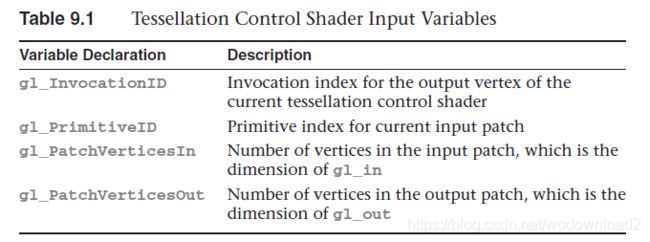
the gl_out array has the same fields, but is a different size specified by gl_PathVerticesOut, which as we say, was set in the tessellation control shader’s out layout qualifier. additionally, the following scalar values, described in Table 9.1 are provided for determining which primitive and output vertex invoation is being shaded:
If you have additional per-vertex attribute values, either for input or output, these need to be declared as either in or out arrays in your
tessellation control shader. The size of an input array needs to be sized to the input-patch size, or can be declared unsized, and OpenGL will appropriately allocate space for all its values. Similarly, per-vertex output attributes, which you will be able to access in the tessellation evaluation shader need to be sized to the number of vertices in the output patch, or can be declared unsized as well.
controlling tessellation
the other function of a tessellation control shader is to specify how much to tessellate the output patch. while we have not discused tessellation evalution shaders in detail yet. they control the type of output patch for rendering, and consequently, the domain where tessellation occurs. opengl supports three tessellation domains: a quadrilaterlal, a triangle, and a collection of isolines.
the amount of tessellation is controlled by specifying two sets of values: the inner-and outer-tessellation levels. the outer-tessellation levels control how the perimeter 外边缘 of the domain is subdivided, and is stored in an implicitly decleared four-element array named gl_TessLevelOuter. similarly, the inner-tessellation levels specify how the inerior of the domain is subdivided. all tessellation level factors are floating-point values, and we will see the effect that fractional values have on tessellations in a bit. one final point is that while the dimensions of the implicitly declared tessellation level factors arrays are fixed, the number of values used from those arrays depends on the type of tessellation domain.
understanding how the inner-and outer-tessellation levels operate is key to getting tessellation to do what u want. each of tessellation level factors specifies how many “segements” to subdivide a region, as well as how many tessellation coordinates and geometric primitives to generate. how that subdivision is done varies by domain type. we will discuss each type of domain in turn, as they operate differently.
quad tessellation
using the quadrilaterial domain may be the most intuitive, so we will begin with it. it is useful when your input patches are rectangular in shape, as u might have when using two-dimensional spline 样条线 surfaces, like Bezier surfaces. the quad domain subdivides the unit square using all of the inner-and outer-tessellation levels. for instance, if we were to set the tessllation level factors to the following values, opengl would tessellate the quad domain as illustrated in firgure 9.1.
关于这个图,我有解释:gl_TessellationInner[0]表示内部区域垂直方向上划分多少块;gl_TessellationInner[1]表示内部区域水平方向上划分多少块;
如下图:
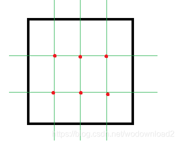
图中的绿色的线是分块的辅助线,gl_TessLevelInner[0] = 3.0; gl_TessLevelInner[1] = 4.0; 垂直方向分为三块,水平方向分为四块,然后交点的红色点,将来是和边上的点进行连接使用。
tessellation levels for quad domain tessellation illustrated in figure 9.1
gl_TessLevelOuter[0] = 2.0;
gl_TessLevelOuter[1] = 3.0;
gl_TessLevelOuter[2] = 2.0;
gl_TessLevelOuter[3] = 5.0;

gl_TessLevelInner[0] = 3.0;
gl_TessLevelInner[1] = 4.0;
这个地方我觉得有点不对,gl_TessLevelOuter[3] = 4.0;吧
notice that the outer-tessellation levels coorespond to the number of segements for each edge around the preimeter, while the inner-tessellation levels specify how many “regions” are in the horizontal and vertical directions in the interior of the domain. also shown in figure 9.1 is a possible triangularization of the domain, shown using the dashed lines. likewise, the solid circles represent the tessellation coordinates, each of which will be provided as input into the tessellation evaluation shader. in the case of quad domain, the tessellation coordinates will have two coordinates, (u,v), which will both be in the range [0,1], and each tessellation coordinate will be passed into an invocation of an tessellation evaluation shader.
isoline tessellation
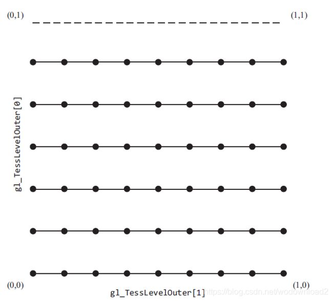
similar to the quad domain, the isoline domain also generate (u,v) pairs as tessellation coordinates for the tessellation evaluation shader. isolines, however, use only two of the outer-tessellation levels to determine the amount of subdivision (and none of the inner-tessellation levels). this is illustrated in figure 9.2 for the tessellation level factors shown in example 9.4.
Example 9.4 Tesslation Levels for an Isoline Domain Tessellation Shown in Figure 9.2
gl_TessLevelOuter[0] = 6;
gl_TessLevelOuter[1] = 8;
You’ll notice that there’s a dashed line along the v = 1 edge. That’s because isolines don’t include a tessellated isoline along that edge, and if you place two isoline patches together (i.e., two patches share an edge), there isn’t overlap of the edges.
Figure 9.2 Isoline tessellation (A tessellation of an isolines domain using the tessellations levels from Example 9.4.)
这个图我又有点疑问了,垂直方向上分成了明明是5块;水平上分为的是8块。为啥gl_TessLevelOuter[0] = 6;???
Triangle Tessellation
Finally, let’s discuss tessellation using a triangle domain. As compared to either the quad or isolines domains, coordinates related to the three vertices of a triangle aren’t very conveniently represented by a (u, v) pair. Instead, triangular domains use barycentric coordinates to specify their Tessellation coordinates. Barycentric coordinates are represented by a triplet of numbers (a, b, c), each of which lies in the range [0, 1], and which have the property that a + b + c = 1. Think of a, b, or c as weights for each individual triangle vertex.
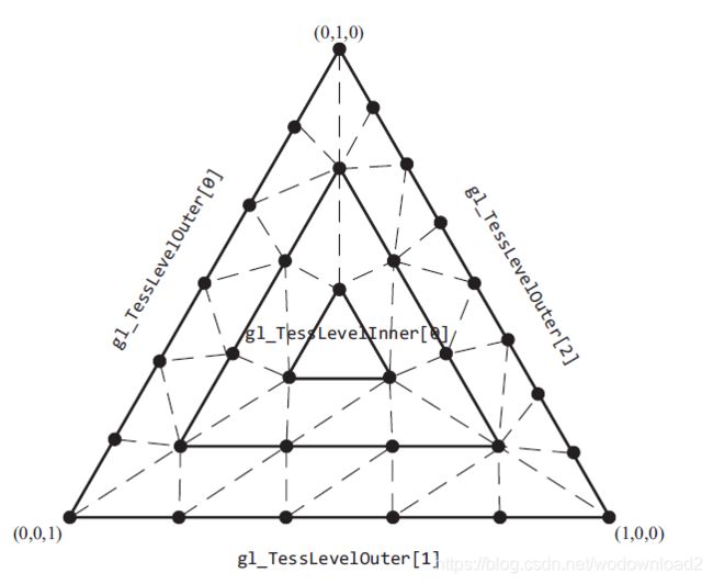
As with any of the other domains, the generated tessellation coordinates are a function of the tessellation level factors, and in particular, the first three outer-tessellation levels, and only inner-tessellation level zero. The tessellation of a triangular domain with tessellation level factors set as in Example 9.5 is shown in Figure 9.3.
Example 9.5 Tesslation Levels for a Triangular Domain Tessellation Shown in Figure 9.3
gl_TessLevelOuter[0] = 6;
gl_TessLevelOuter[1] = 5;
gl_TessLevelOuter[2] = 8;
gl_TessLevelInner[0] = 5;
Figure 9.3 Triangle tessellation (A tessellation of a triangular domain using the tessellation levels from Example 9.5.)
As with the other domains, the outer-tessellation levels control the subdivision of the perimeter of the triangle and the inner-tessellation level controls how the interior is partitioned. As compared to the rectangular domains, where the interior is partitioned in a set of rectangles forming a grid, the interior of the triangular domain is partitioned into a set of concentric triangles that form the regions. Specifically, let t represent the inner-tessellation level. If t is an even value, then the center of the triangular domain (barycentric coordinate (1/2 , 1/2
, 1/2) is located, and then (t/2) − 1 concentric triangles are generated between the center point and the perimeter. Conversely, if t is an odd value, then (t/2) − 1 concentric triangles are out to the perimeter, however, the center point (in barycentric coordinates) will not be a tessellation coordinate. These two scenarios are shown in Figure 9.4.
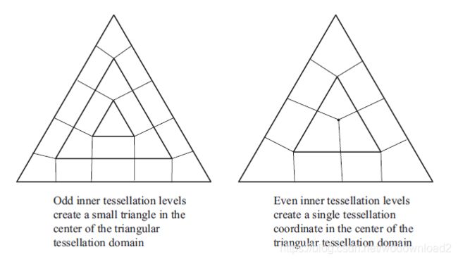
Figure 9.4 Even and odd tessellation (Examples of how even and odd inner tessellation levels affect triangular tessellation.)
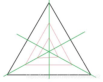
关于这个图,我有话说,如果gl_TessLevelInner[0] = 5;为奇数,那么由中心点到边有5/2-1个三角形=2个。5/2向上取整。
如果gl_TessLevelInner[0] = 4;为偶数,则4/2-1=1个三角形。
以gl_TessLevelInner[0] = 5;为例子:
tessellation evaluation shaders
the final phase in opengl’s tessellation pipeline is the tessellation evaluation shader execution. the bound tessellation evaluation shader is executed one for each tessellation coordinate that the primitive generator emits, and is responsible for determinng the position of the vertex derived from the tessellation coordinate. 由细分坐标推导出顶点的位置。as we will see, tesellation evaluation shaders look similar to vertex shaders in transforming vertices into screen positions (unless the tessellation evaluation shader’s data is going to be further processed by a geometry shader).
the first step in configuring a tessellation evaluation shader is to configure the primitive generator, which is done using a layout directive, similar to what we did in the tessellation control shader. its parameters specify the tessellation domain and subsequently,
the type of primitives generated;
face orientation for solid primitives (used for face culling);
and how the tessellation levels should be applied during primitive generation.
specifying the primitive generation domain
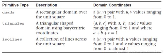
we will now describe the parameters that u will use to set up the tessellation evaluation shader’s out layout directive. first, we will talk about sepcifying the tessellation domain. as u have seen, there are three types of domains used for generating tessellation coordinates, which are described in table 9.2.
Table 9.2 Evaluation Shader Primitive Types
specify the face winding for generated primitives
as with any filled primitive in opengl, the order the vertices are issued determines the facedness of the primitive. since we do not issue the vertices directly in this case, but rather have the primitive generator do it on our behalf, we need to tell it the face winding of our primitives. in the layout directive, specify cw for clockwise vertex winding or ccw for couterclock-wise vertex winding.
specifying the spacing of tessellation coordinates
additionally, we can control how fractional values for the outer-tessellation levels are used in determining the tessellation coordinate generation for the perimeter edges. (inner-tessellation levels are affected by these options.)
table 9.3 describes the three spacing options available, where max represents an opengl implementation’s maximum accepted value for a tessellation level.
Table 9.3 Options for Controlling Tessellation Level Effects

Additional Tessellation Evaluation Shader layout Options
Finally, should you want to output points, as compared to isolines or filled regions, you can supply the point_mode option, which will render a single point for each vertex processed by the tessellation evaluation shader. The order of options within the layout directive is not important. As an example, the following layout directive will request primitives generated on a triangular domain using equal spacing, counterclockwise-oriented triangles, but only rendering points, as compared to connected primitives.
layout (triangles, equal_spacing, ccw, points) out;
Specifying a Vertex’s Position
The vertices output from the tessellation control shader (i.e., the gl_Position values in gl_out array) are made available in the evaluation
498 Chapter 9: Tessellation Shaders www.it-ebooks.info shader in the gl_in variable, which when combined with tessellation coordinates, can be used to generate the output vertex’s position.
Tessellation coordinates are provided to the shader in the variable gl_TessCoord. In Example 9.6, we use a combination of equal-spaced
quads to render a simple patch. In this case, the tessellation coordinates are used to color the surface, and illustrates how to compute the vertex’s position.
Example 9.6 A Sample Tessellation Evaluation Shader
#version 420 core
layout (quads, equal_spacing, ccw) in;
out vec4 color;
void main()
{
	float u = gl_TessCoord.x;
	float omu = 1 - u; // one minus "u"
	float v = gl_TessCoord.y;
	float omv = 1 - v; // one minus "v"
	color = gl_TessCoord;
	gl_Position = omu * omv * gl_in[0].gl_Position + u * omv * gl_in[1].gl_Position +
					u * v * gl_in[2].gl_Position + omu * v * gl_in[3].gl_Position;
}
Tessellation Evaluation Shader Variables
Similar to tessellation control shaders, tessellation evaluation shaders have a gl_in array that is actually an array of structures, with each element defined as shown in Example 9.7.
Example 9.7 gl_in Parameters for Tessellation Evaluation Shaders
in gl_PerVertex
{
	vec4 gl_Position;
	float gl_PointSize;
	float gl_ClipDistance[]
} gl_in[gl_PatchVerticesIn];
Additionally, the following scalar values, described in Table 9.4, are provided for determining which primitive and for computing the position of the output vertex.
Table 9.4 Tessellation Control Shader Input Variables
The output vertex’s data is stored in an interface block defined as follows: 啥是接口块
out gl_PerVertex
{
	vec4 gl_Position;
	float gl_PointSize;
	float gl_ClipDistance[]
};
a tessellation example: the teapot
all of that theory could use a concrete demonstration. in this section, we will render the famous utah teapot using Bezier patches. a Bezier patch, named after french engineer pierre bezier, defines a parametric surface evaluated over the unit square using control points arranged in a grid. for our example, we will use 16 control points arranged in a 4x4 grid. as such, we make the following observations to help us set up our tessellation:
- Bezier patches are defined over the unit squre, which indicates we should use the quads domain type that we will specify in our layout directive in the tessellation evaluation shader.
- each patch has 16 control points, so our GL_PATCH_VERTICES should be set to 16 using glPatchParameteri().
- the 16 control points also define the number of input-patch vertices, which tells us our maximum index into the gl_in array in our tessellation control shader.
- finally, since the tessellation control shader does not add or remove any vertices to the patch, the number of output-patch vertices will also be 16, which specifies the value we will use in our layout directive in the tessellation control shader.
processing patch input vertices
given the information from our patches, we can easily construct the tessellation control shader for our application, which is shown in example 9.8.
example 9.8 tessellation control shader for teapot example
#version 420 core
layout (vertices = 16) out;
void main()
{
	gl_TessLevelInner[0] = 4;
	gl_TessLevelInner[1] = 4;
	gl_TessLevelOuter[0] = 4;
	gl_TessLevelOuter[1] = 4;
	gl_TessLevelOuter[2] = 4;
	gl_TessLevelOuter[3] = 4;
	gl_out[gl_InvocationID].gl_Position = gl_in[gl_InvocationID].gl_Position;
}
using the tessellation level factors from example 9.8, firgure 9.5 shows the patches of the teapot (shrunk slightly to expose each individual patch).
this is a very simple example of a tessellation control shader. in fact, it is a greate example of a pass-through shader, where mostly the inputs are copied to the output. the shader also sets the inner-and outer-tessellation levels to constant values, which could also be done in the application using a call to glPatchParameterfv(). however, we include the example here for completeness.
evaluating tessellation coordinates for the teapot
Bezier patches use a bit of mathematics to determine the final vertex position from the input control points. the equation mapping a tessellation coordinate to a vertex position for our 4x4 patch is:

with p being the final vertex position, v the input control point at index (i,j) in our input patch (both of whcih are vec4s in glsl), and B which are two scaling functions.
while it might not seem like it, we can map easily the formula to a tessellation evaluation shader, as show in example 9.9. in the following shader, the B function will be a glsl function we will define in a moment.
we also specify our quads domain, spacing options, and polygon face orientation in the layout directive.
Example 9.9 The Main Routine of the Teapot Tessellation Evaluation Shader
#version 420 core
layout (quads, equal_spacing, ccw) out;
uniform mat4 MV; // Model-view matrix
uniform mat4 P; // Projection matrix
void main()
{
	vec4 p = vec4(0.0);
	float u = gl_TessCoord.x;
	float v = gl_TessCoord.y;
	for (int j = 0; j < 4; ++j)
	{
		for (int i = 0; i < 4; ++i)
		{
			p += B(i, u) * B(j, v) * gl_in[4*j+i].gl_Position;
		}
	}
	gl_Position = P * MV * p;
}
our B function is one of the Bernstein polynomials, which is an entire family of mathematical functions. each one returns a scalar value. we are using a small select set of functions which we index using the first parameter, and evaluate the function’s value at one component of our tessellation coordinate. here is the mathematical definition of our functions

where the ![]() is a particular instance of a mathematical construct called a binomial coefficient. we will spare u the gory details and just say we are lucky that it evaluates to either 1 or 3 in our cases, and which we will hard code into a lookup table, bc in the function’s definition, and that we will index using i. as such, we can rewrite B(i,u) as
is a particular instance of a mathematical construct called a binomial coefficient. we will spare u the gory details and just say we are lucky that it evaluates to either 1 or 3 in our cases, and which we will hard code into a lookup table, bc in the function’s definition, and that we will index using i. as such, we can rewrite B(i,u) as

this also translates easily into glsl, shown in example 9.10
Example 9.10 Definition of B(i, u) for the Teapot Tessellation Evaluation Shader
float B(int i, float u)
{
	// Binomial coefficient lookup table
	const vec4 bc = vec4(1, 3, 3, 1);
	return bc[i] * pow(u, i) * pow(1.0 - u, 3 - i);
}
while that conversion involved more mathematics than most of the other techniques we have described in the book, it is representative of what u will encounter when working with tessellated surfaces. while discussion of the mathematics of surfaces is outside of this text, copious 大量的 resources are available that describe the required techniques.
additional tessellation techniques
in this final section, we briefly describe a few additional techniques u can employ while using tessellation shaders.
view dependent tessellation
most of the examples in this chapter have set the tessellation level factors to constant values (either in the shader or through uniform variables). one key feature of tessellation is being able to compute tessellation levels dynamically in the tessellation control shader, and in particular, basing the amount of tessellation on view-dependent parameters.
for example, u might implement a level-of-detail scheme based on the distance of the patch from the eye’s location in the scene. in example 9.11, we use the average of all the input-patch vertices to specify a single representive point for the patch, and derive all the tessellation level factors from the distance of that point to the eye point.
Example 9.11 Computing Tessellation Levels Based on View-Dependent Parameters
uniform vec3 EyePosition;
void main()
{
	vec4 center = vec4(0.0);
	for (int i = 0; i < gl_in.length(); ++i)
	{
		center += gl_in[i].gl_Position;
	}
	center /= gl_in.length();
	float d = distance(center, vec4(EyePosition, 1.0));
	const float lodScale = 2.5; // distance scaling variable
	float tessLOD = mix(0.0, gl_MaxTessGenLevel, d * lodScale);
	for (int i = 0; i < 4; ++i)
	{
		gl_TessLevelOuter[i] = tessLOD;
	}
	tessLOD = clamp(0.5 * tessLOD, 0.0, gl_MaxTessGenLevel);
	gl_TessLevelInner[0] = tessLOD;
	gl_TessLevelInner[1] = tessLOD;
	gl_out[gl_InvocationID].gl_Position = gl_in[gl_InvocationID].gl_Position;
}
example 9.11 is a very rudimentary 基础的 method for computing a patch’s level of detail. in particular, each perimeter edge is tessellated the same amount, regardless of its distance from the eye. this does not take full advantage of tessellation possibilities based on view information, which is ususally employed as a geometry optimization technique (i.e., reducing the object’s geometric complexity the farther from the eye that object is, assuming a perspective projection is used). another failing of this approach is that if u have multiple patches that share edges, it is likely that the shared edges may be assigned different levels of tessellation depending on the object’s orientation with respect to the eye’s position, and that might lead to cracking 裂纹 along the shared edges. carcking is an important issue with tessellation, and we address another concern in “shared tessellated edges and cracking” on page 506.
to address guraranteeing that shared edges are tessellated the same, we need to find a method that returns the same tessellation factor for those edges. however, as compared to example 9.11, which does not need to know anything about the logical ordering of input-patch vertices, any algorithm that needs to know which vertices are incident on a perimeter edge is data-dependent. this is because a patch is a logical ordering——only the application knows how it ordered the input-patch vertices. for example, 9.12, we introduce the following array of structures that contain our edge information for our tessellation control shader.
