2 Robotics: Computational Motion Planning 第2+3+4周 课后习题解答
Computational Motion Planning 第2+3+4周
- 2 Robotics: Computational Motion Planning
- WEEK - 2
- Quiz
- Configuration Space: Part 1 of 2
- ==Configuration Space: Part 2 of 2==
- WEEK - 3
- Quiz
- Assignment: Random Sampling Approaches
- WEEK - 4
- Quiz
- Assignment: Gradient Based Planner
首先这个系列的第一个单元是空中机器人,博客如下:
1 Robotics: Aerial Robotics 第1+2周 课程学习记录及课后习题解答
1 Robotics: Aerial Robotics 第3+4周 课程学习记录及课后习题解答
2 Robotics: Computational Motion Planning 第1周(内含Dijkstra 和 A* MATLAB代码手把手教学)课后习题解答
此课程在Coursera需要科学上网才能观看,放一下B站和Coursera的课程链接
- UP主 博主自己做的字幕版本 第二单元更新完毕
- Coursera的链接介绍
此文仅为听课记录以及做题思考,可以的话我会将题目和代码题都搬运一下
VS 为视频字幕,MI为个人想法,有所错误或是好的想法欢迎评论区交流。(点个赞就更好了,鼓励一下~)
- 2.20:emm,2.24就有完整的了,这不完整的连编程都没法往下做(这个单元课编程作业都不有什么说明… 不像空中机器人的编程作业都有单独的pdf来说明)
- 2.21:今天把第3周的课都更新完吧… 再拖着后面的课可能比较慢
- 2.24:大清早,申请就下来了,OKOK开始把编程作业搞完,我发现… 原来是有编程作业的解释,必须得有课程权限才能点进去(旁听是不行的…),所以我就复制在下面了吧
- 2.24:!!!!心里一万头草泥马奔腾… 我卡那个第二周的第二作业卡了一下午!在MATLAB上显示全部正确,然后一直通过不了那个固定的例子… (然后我就借鉴大法,把Github里的找了大半,直接复制… 发现都过不了)然后!!我在评论区找到了解答… 详情看下面吧(好处是:一个题目我见识了N种写代码的方式,有一种4行代码解决一下,牛皮)
- 2.25:哈哈哈哈哈哈,哈哈哈哈哈哈!做完啦!(真心为后面申请这个课的人提个建议:编程做不出来或者总觉得有问题的时候课程的论坛可以先看看,老师会给点思路,直接看代码… emm 虽然我是这样的,可能会学不太深)再次贴个证书,在回校前看看能不能完成所有的6单元的。
2 Robotics: Computational Motion Planning
WEEK - 2
Quiz
1.Configuration Space obstacles allow us to model:
Both the geometry of the robot and the shapes of the obstacles in the environment
2.The effective dimension of the configuration space of the robot is determined by:
The number of joints or degrees of freedom that the robot mechanism has. For example a robots that can translate and rotate in the plan will have a 3 dimensional configuration space reflecting 2 degrees of translational freedom and 1 rotational. A robot with 5 revolute joints will have a 5 dimensional configuration space.
3.True or false: the Visibility graph method is complete because it will always find a path through space if one exists and report failure if there is no path.
True
4.True or false, the Trapezoidal Decomposition method is complete because it will always find a path through space if one exists and report failure if there is no path.
True
Configuration Space: Part 1 of 2
INRTODUCTION
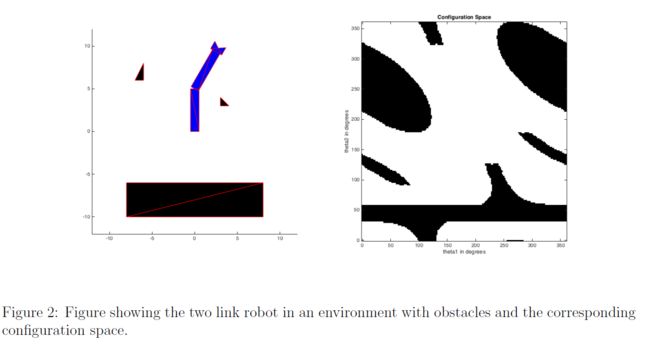
The primary objective of the Configuration Space programming assignment is to provide the students with experience in practical application of Configuration Space usage in real world environments. In this programming assignment, you will be writing a program to help guide a two link robotic arm from one configuration space to another while avoiding obstacles in the workspace. The purpose of this assignment is to provide you with some experience working with representation of configuration space. The configuration of the robot is captured by two joint angles, 0, and 62, as shown in Figure 1. These angles are represented with values between 0 to 360 degrees.

INRTODUCTION OF TRIANGLES
For this particular assignment, since the robotic arm and the obstacles are assumed to be a collection of triangles, any form of real world collision is simplified to the fact of intersection between the triangles of the robotic arm and the obstacle.
One of the many approaches towards understanding this concept is to consider all the 6 edges(3 for each triangle)and whether they act as separating lines where all verticesot one triangle lie on one side.
Also, the possible scenarios to check for are as follows:

Moving from left to right, the possible scenarios include:
- Non intersecting triangles
- Triangles intersecting at a single point(one line-one point)
- Triangles intersecting at a single point (one point-one point)
- Triangles intersecting via line overlap
- Triangles intersecting at multiple points
- One triangle overlapping the other
FUNCTION DESCRIPTION
For this part of the assignment you have to create the function triangle_intersection with the following input and output arguments:
P1, P2: a 3x2 array(each), describing the vertices of a triangle, where the first column represents x coordinates and the second column represents y coordinates.
flag: Return value for the function, set to true if determines intersection (including overlapping) between triangles and false otherwise.
Once completed, you can try out multiple scearios to check if your algorithm works for all cases as discussed above.
简单点来说以上的文档:就是——你的函数需要判断两个三角形是否有相交部分。三角形数据给出的是3x2的矩阵。剩下的是数学的锅,在此贴一下从严谨的数学角度去思考,(看完大家可以自己先写一遍,编程嘛 过程肯定不同)数学美 之 判断线段相交的最简方法
另一位博主也写了自己的寻找路程:检测两个三角形是否有重叠面积/相交的方法
但是呢,我直接说个看了之后的简单方法吧,给各位看了其他人写的过多的一个更好的方法。
首先我得知道:这里是证明:行列式求三角形面积
结论是:三角形ABC在平面直角坐标系内 A ( a , b ) , B ( c , d ) , C ( e , f ) A(a,b),B(c,d),C(e,f) A(a,b),B(c,d),C(e,f)那么,三角形的面积可以表示为:(证明如上)
S Δ = 1 2 ∣ a b 1 c d 1 e f 1 ∣ S{}_\Delta {\rm{ = }}\frac{1}{2}\left| {\begin{array}{cc} a&b&1\\ c&d&1\\ e&f&1 \end{array}} \right| SΔ=21∣∣∣∣∣∣acebdf111∣∣∣∣∣∣
然后是什么呢?
Function
function flag = triangle_intersection(P1, P2)
% triangle_test : returns true if the triangles overlap and false otherwise

%%% All of your code should be between the two lines of stars.
% *******************************************************************

flag=Pointin(P1,P2);
if flag==false
    flag=Pointin(P2,P1);
end
	%此处函数判断P2三角形的各点是否在P1三角形内
    function Point = Pointin(Po1,Po2)
        base=[Po1 ones(3,1)];
        Area_base=0.5*det(base);
        Point = false;%false
        for i=1:3
            Area=abs(Cal_Area(Po2(i,:),Po1(1:2,:)));
            Area=Area+abs(Cal_Area(Po2(i,:),Po1(2:3,:)));
            Area=Area+abs(Cal_Area(Po2(i,:),[Po1(1,:);Po1(3,:)]));
            if Area==Area_base
                Point = true;%true
                break;
            end
        end
    end
	%此处函数计算面积
    function Area = Cal_Area(temp,Tra)
        Area=0.5*det([[temp;Tra] ones(3,1)]);
    end
% *******************************************************************
end
Code to call you function
x = [2,2,3];
y = [5,3,4];
P1 = [x;y]';

x = [0,4,2];
y = [0,4,6];
P2 = [x;y]';

line([P1(:,1)' P1(1,1)],[P1(:,2)' P1(1,2)],'Color','r')
line([P2(:,1)' P2(1,1)],[P2(:,2)' P2(1,2)],'Color','b')

flag = triangle_intersection(P1,P2);
if flag == 1
    disp("Intersection")
else
    disp("No Intersection")
end
Configuration Space: Part 2 of 2
INTRODUCTION
In the previous part of the assignment,you implemented an algorithm to check if two triangles intersect with each other at any point.Since,the robotic arm and the obstacles are a group of triangles,the means to check if a configuration is viable or not becomes indispensable.
For Week 1 homework assignment you were asked to complete the function DijkstraGrid which was used to plan paths through simple grid based environments,modeled using 2D logical arrays.In the following part of the assignment you are going to extend that idea by completing the function DijkstraTorus.
DijkstraTorus takes in the configuration space,as derived from the triangle intersections between the robotic arm and the obstacles in the workspace,and implements the Dijkstra’s algorithm to calculate the shortest feasible route from a starting configuration to the ending configuration.
IMPLEMENTATION
The input and output arguments for this function are explained below:
- input map: a logical array where the freespace cells are false or 0 and the obstacles are true or 1
- start_coords, dest_coords: Coordinates of the start and end cell respectively, the first entry is the row and the second the column.
- route: An array containing the linear indices of the cells along the shortest route from start to dest or an empty array if there is no route.
Note:
- The particular function contains a variable label which gives you the choice of whether you wish to see the output of the function or not.
- The following code uses an existing version of triangle_intersection. m as it is crucial in the implementation of DijkstraTorus. If you wish to apply your version of the code, plug in your code in the triangle_intersection.m provided in the matlab zip File link provided below.
- For simplicity and reduction of computation time, an existing -configuration space has already been loaded. The code to create this configuration space is mentioned in TwoLinkCspace. m in the MATLAB zip file link below
- If you wish to see the animation of how your code works, download the MaTLAB zip file from the summary window in the previous screen and plug in your code.
这个我真的快被坑死了!!!还是讨论区牛皮,一句话说明一下会存在的问题:
1. 不能直接复制第一周的dijkstra的代码,因为这次,你是可以穿越边界的(注意此时是位形空间),你在计划的东东是这个:(听不懂这行就看一下b站视频)
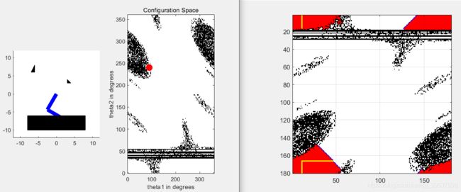
emm 这个阴影大家不要介意… 这是三角形那个相交生成的障碍较稀疏的问题,言归正转,所以看到了吗,这里是能穿越边界的
2. 这个其实… 不算我们的锅,但是就是让我找了一下午的bug,一直通不过那个。
讨论区链接直达
请复制这行代码在[nrows, ncols] = size(input_map);这个之前如下:
%Add these lines of code before [nrows, ncols] = size(input_map);---------------------------------------It's very important

input_map(:, 181) = [];
input_map(181, :) = [];

[nrows, ncols] = size(input_map);
不然得话,你就会出现以下错误:
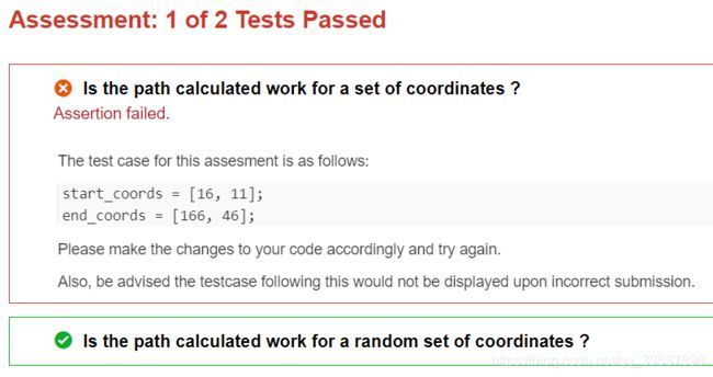
没错就是第一个例子怎么都过不了,然后加上上面我说的,就能成功了,完整代码如下:
function route = DijkstraTorus (input_map, start_coords, dest_coords)
    % Run Dijkstra's algorithm on a grid.
% Inputs :
%   input_map : a logical array where the freespace cells are false or 0 and
%      the obstacles are true or 1
%   start_coords and dest_coords : Coordinates of the start and end cell
%       respectively, the first entry is the row and the second the column.
% Output :
%   route : An array containing the linear indices of the cells along the
%    shortest route from start to dest or an empty array if there is no
%    route.

% set up color map for display
% 1 - white - clear cell
% 2 - black - obstacle
% 3 - red = visited
% 4 - blue  - on list
% 5 - green - start
% 6 - yellow - destination

cmap = [1 1 1; ...
        0 0 0; ...
        1 0 0; ...
        0 0 1; ...
        0 1 0; ...
        1 1 0];

colormap(cmap);

label = true;

%Add these lines of code before---------------------------------------It's
%very important
input_map(:, 181) = [];
input_map(181, :) = [];

[nrows, ncols] = size(input_map);

% map - a table that keeps track of the state of each grid cell
map = zeros(nrows,ncols);

map(~input_map) = 1;  % Mark free cells
map(input_map)  = 2;  % Mark obstacle cells

% Generate linear indices of start and dest nodes
start_node = sub2ind(size(map), start_coords(1), start_coords(2));
dest_node  = sub2ind(size(map), dest_coords(1),  dest_coords(2));

map(start_node) = 5;
map(dest_node)  = 6;

% Initialize distance array
distances = Inf(nrows,ncols);

% For each grid cell this array holds the index of its parent
parent = zeros(nrows,ncols);

distances(start_node) = 0;

% Main Loop
while true

    % Draw current map
    map(start_node) = 5;
    map(dest_node) = 6;

    %image(1.5, 1.5, map);
    %grid on;
    %axis image;
    %drawnow;
%
    % Find the node with the minimum distance
    [min_dist, current] = min(distances(:));

    if ((current == dest_node) || isinf(min_dist))
        break;
    end;

    % Update map
    map(current) = 3;         % mark current node as visited
    distances(current) = Inf; % remove this node from further consideration

    % Compute row, column coordinates of current node
    [i, j] = ind2sub(size(distances), current);

    % Visit each neighbor of the current node and update the map, distances
    % and parent tables appropriately.

    %%% All of your code should be between the two lines of stars.
    % *******************************************************************
    %i是row j是col
    south_node=[i,j-1];
    north_node=[i,j+1];
    east_node=[i+1,j];
    west_node=[i-1,j];
    neighbourhood=[south_node;north_node;west_node;east_node];
    if(i==1)
        neighbourhood(3,:)=[nrows, j];
    end
    if (i == nrows)
        neighbourhood(4,:) =[1, j];
    end
    if (j == 1)
        neighbourhood(1,:) = [i, ncols];
    end
    if (j == ncols)
        neighbourhood(2,:) = [i, 1];
    end
    for k=1:4
        update(neighbourhood(k,1),neighbourhood(k,2),1+min_dist,current);
    end
    % *******************************************************************
end

if (isinf(distances(dest_node)))
    route = [];
else
    route = [dest_node];

    while (parent(route(1)) ~= 0)
        route = [parent(route(1)), route];
    end
    drawMap(label);
end

    function update (i,j,d,p)
        if ( (map(i,j) ~= 2) && (map(i,j) ~= 3) && (map(i,j) ~= 5) && (distances(i,j) > d) )
            distances(i,j) = d;
            map(i,j) = 4;
            parent(i,j) = p;
        end
    end

    function drawMap(label)
        if label==true
        for kk = 2:length(route) - 1
            map(route(kk)) = 7;
        end
        image(1.5, 1.5, map);
        grid on;
        axis image;
        end
    end
end
直接复制就能全过了… (多余的第一周都讲完了,如果现在还看不懂代码… 我只能说重新听遍课吧)
这个是我无意之中发现的大佬四行代码系列
    %%% All of your code should be between the two lines of stars.
    % *******************************************************************
    update((mod(i  ,nrows)+1),j,(min_dist+1),current);
    update((mod(i-2,nrows)+1),j,(min_dist+1),current);
    update(i,(mod(j,ncols  )+1),(min_dist+1),current);
    update(i,(mod(j-2,ncols)+1),(min_dist+1),current);
    % *******************************************************************
WEEK - 3
这周,专门讲的是:
PRM——随机路标图
RRT——快速搜索树
有关博客链接(博客园):
PRM路径规划算法
RRT路径规划算法
Quiz
1.True or false : The Probabilistic RoadMap procedure tries to builds a graph that captures the structure of the entire configuration space before it tries to find a route between two points.
True
2.True or false: the Probabilistic Roadmap (PRM) method is complete because it will always find a path through space if one exists and report failure if there is no path.
False
3.True or false: the Rapidly Exploring Random Tree (RRT) method is complete because it will always find a path through space if one exists and report failure if there is no path.
False
解释:视频中也说了RRT是大概率上是完整的,也就是绝大部分都能找到路径
Assignment: Random Sampling Approaches
INTRODUCTION
In this assignment you will be writing a program to help guide a six link robot shown in the figurel below from one configuration to another while avoiding the objects in the workspace.This assignment will give you some experience working with planning methods based on random sampling.The robot shown in the figure below is comprised of six revolute links and its configuration can be specified with a vector ( θ 1 , θ 2 , θ 3 , θ 4 , θ 5 , θ 6 ) (\theta_1,\theta_2,\theta_3,\theta_4,\theta_5,\theta_6) (θ1,θ2,θ3,θ4,θ5,θ6) where each entry is an angle between 0-360 degrees.
CONCEPT
In the previous assignment, you designed a path planning algortihm based on a configuration space for a robotic arm moving in two dimensions. The same concept can be extrapolated to multiple dimensions as well. However, with increasing the number of dimensions, the complexity of the configuration space increases just as much, not to mention the severe increase in the computation power.
As an alternative, the points in the configuration space can be chosen randomly instead of uniformly On every iteration, the system will choose a configuration in the configuration space at random, and tests whether it is in free space using the collision check function. On achieving success, the configuration is added to the list of other points to form a path between the start and goal.
IMPLEMENTATION
Your main job for this assignment is to complete the PRM function which computes a probabilistic road map of the configuration space.
The input arguments to this function are explained below:
- RandomSample: a function which returns a random sample in freespace
- Dist: a function which can be used to compute the distance between a given random sample and all of the samples generated so far
- LocalPlanner: a function that can be used to test whether two configuration space points, x1 and x2, can be joined by a straight line. That is LocalPlanner(x1, x2)will only return true if the straight line between x1 and x2 does not intersect any configuration space obstacles
- nsamples: the total number of random samples to be generated
- k : number of neighboring samples to be considered during PRM construction
ALGORITHM
The section of code that you are asked to complete should perform the following steps:
- Use the array distances generated by Dist function to determine the indices of the k nearest neighbors. (Hint: you may find the sort function useful here.)
- For each of those neighbors, it should determine whether or not it can forge a path between those two locations using the LocalPlanner function
- If a path exists, it should then update the set of edges as follow:
Add an entry to edges array indicating the indices of the two samples that have just been joined.
Add a corresponding entry to the edge lengths array indicating the length of this new edge.
Increment the nedges variable to reflect the fact that a new node has been added.
These edges and edge lengths contitute a graph which will be used later by the ShortestPathDijkstra routine to plan paths through the roadmap.
NOTE:
- The number of samples have been predefined to 100 samples since the code becomes computationally expensive with further samples and causes the online grader to timeout. If you wish to see use a greater number of samples, please download the skeleton code from the link below plug in your code and the new sample number (nsamples) in SixLinkPRMScript.m
- The image displayed as an output displays the configuration of the robot at one particular point (midway between total set of configurations). If you wish to see the complete animation, please download the skeleton code from the link below and plug in your code in PRM.m
这个地方是我是真不知道怎么讲,分析代码都分析了好久,直接贴一下我的过程吧,大家随缘看懂,最好自己拿MATLAB逐步去运行一下,我的笔记就当自己的前人理解吧…(这个虽然看着简单,但是做着可真不简单)
此图是自己的理解过程图:

完整代码如下:
function roadmap = PRM (RandomSample, Dist, LocalPlanner, nsamples, k)
% PRM - ProbablisticRoadMap : This procedure computes a probabilistic road
% map of configuration space. It relies on 3 functions
% RandomSample which generates the coordinate vector for a random sample in
% free space. Dist which measures the distance between two
% coordinate vectors and LocalPlanner which decides whether two samples are
% connected.
%
% Inputs :
%
%   RandomSample : A function that returns a random sample in freespace
%
%   Dist : A function that computes the distance between a given point in
%        configuration space and all of the entries in an array of samples
%
%   LocalPlanner :  A function that determines whether there is a collision
%        free straight line path between two points in configuration space
%
%   nsamples : The number of random samples to generate
%
%   k : The number of neighbors that should be considered in
%        forming the roadmap graph.
%
% Output :
%   roadmap - a structure the samples, the edges and edge lengths in the
%        roadmap graph

x = RandomSample();

% Array of random samples, each column corresponds to the coordinates
% of a point in configuration space.
samples = repmat(x(:), 1, nsamples);

% edges - an array with 2 rows each column has two integer entries
% (i, j) which encodes the fact that sample i and sample j are connected
% by an edge. For each
edges = zeros(nsamples*k, 2);
edge_lengths = zeros(nsamples*k, 1);

% nedges - this integer keeps track of the number of edges we
% have in the graph so far
nedges = 0;

for i = 2:nsamples
    % Note that we are assuming that RandomSample returns a sample in
    % freespace
    x = RandomSample();

    samples(:,i) = x(:);

    % Find the nearest neighbors

    % Here we assume that the Dist function can compute the
    % distance to multiple samples corresponding to the columns of
    % the second argument
    % at the end of this call the array distances will indicate the
    % distance between the new sample and each of the samples that has been
    % generated so far in the program.
    distances = Dist(x, samples(:,1:(i-1)));%计算x与samples的1:i列的距离,返回整体i-1个距离

    %%% YOUR CODE HERE
    %
    % Find the closest k samples, use the LocalPlanner function to see if
    % you can forge an edge to any of these samples and update the edges,
    % edge_lengths and nedges variables accordingly.
    %
    n=length(distances);%抽取几份 样本点
    [sort_dis,idx]=sort(distances);%排序样本点距离,看哪个更近点
    for mi=1:min(k,n)%因为需要的是k个,只取前k个,但是不足k的时候就是n
        mj=idx(mi);%第mi个小的距离标号
        if(LocalPlanner(x,samples(:,mj)))%看看属于哪个,判断是否能连成线(不碰到障碍)
            nedges=nedges+1;%可以的话,就已经有了一个边点了,下面是记录
            edges(nedges,:)=[n+1,mj];
            edge_lengths(nedges)=sort_dis(mi);
        end
    end
    fprintf (1, 'nsamples = %d, nedges = %d\n', i, nedges);

end

roadmap.samples = samples;
roadmap.edges = edges(1:nedges, :);
roadmap.edge_lengths = edge_lengths(1:nedges);
WEEK - 4
Quiz
1.Artificial Potential Fields are designed to (click all that apply):
Atrract the robot to the goal
Repel the robot from obstacles
2.True or false: the Artificial Potential field method is complete because it will always find a path through space if one exists and report failure if there is no path.
False
3.True or false: Artificial Potential Field methods can lead the robot to become stuck at locations other than the desired goal location.
True
Assignment: Gradient Based Planner
INTRODUCTION
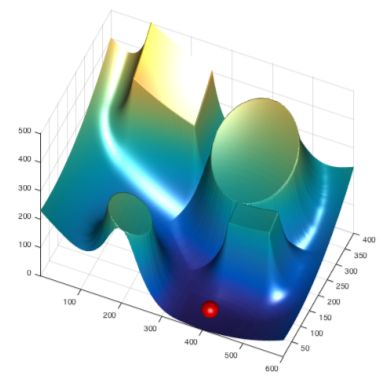
In this assignment you will be developing code to guide a robot from one location to another in a 2 dimensional configuration space using artificial potential fields.The figure below depicts a plot of the energy surface associated with our sample environment and the state of the robot is modeled by the red sphere which we can be thought of as roling down the energy surface towards the goal location.
IMPLEMENTATION
Your job is to complete the function named GradientBasedPlanner which is used to control the motion of the robot. The signature of the function is given below.
The input arguments to this function are explained below.
- f: A2D array containing the potential function values.
- start_coords: An array specifying the coordinates of the start location the first entry is the x coordinate and the second the y.
- end_coords: An array specifying the coordinates of the goal the first entry is the x coordinate and the second the y.
- max_its: The maximum number of iterations that should be tried by the planner.
ALGORITHM
The section of code that you are asked to complete should perform the following procedure
- On every iteration the planner should update the position of the robot based on the gradient values contained in the arrays gx and gy. Make sure you normalize the gradient vectors.
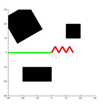
- Update the route by adding the new position of the robot to the end of the route array. Note that the distance between successive locations in the route should not be greater than 1.0.
- Continue the same procedure until the distance between the robot’s current position and the goal is less than 2.0 or the number of iterations exceeds the value contained in max_its.
NOTE
- For reducing computation time,the displays have been turned off.If you wish to observe the images change the "display_"values accordingly.Please observe one image at a time since the code times out otherwise.
- If you wish to observe the animation of the route followed by the ball,please download the skeleton code from the summary window in the previous screen and plug in your code in GradientBasedPlanner.m
这个作业其实很简单,但是有几个点:(复制一下论坛里的大家参考一下)
具体链接 Week -4 Programming Assignment Tips
I think that most of the learners here facing the same problem with the grader. Here’s my tips if you think you generated the right answer and the grader still considered it incorrect.
(You can add your tips in the comment to help future learners in case I miss something)
1.Swap x and y index.
This is a bit confusing. Your start_coord comes in x and y pair. To take the gradient out of the function, gx and gy, you should put the x from start_coords as the second argument for gx and gy and y from start_coords as the first argument for gx and gy.
Why is this? Well, remember that we use bwdist() function which belongs to image processing package. So, we treat the map as image, so does the generated gradient. Cartesian X coordinate is in the horizontal axis, while in the image, horizontal axis belongs to Width/Column. Remember (x, y) and (row, col) convention!
2.NORMALIZE!
3.Use round() instead of floor()
4.Include the start_coords in the route. This leaves you to iterate only max_its-1 times.
5.Terminate if the distance of your latest route to end_coords is < 2. Just terminate it even it still can iterate.
6.Convert your route to have double precision by simply, route = double(route);
然后直接贴代码了:
function route = GradientBasedPlanner (f, start_coords, end_coords, max_its)
% GradientBasedPlanner : This function plans a path through a 2D
% environment from a start to a destination based on the gradient of the
% function f which is passed in as a 2D array. The two arguments
% start_coords and end_coords denote the coordinates of the start and end
% positions respectively in the array while max_its indicates an upper
% bound on the number of iterations that the system can use before giving
% up.
% The output, route, is an array with 2 columns and n rows where the rows
% correspond to the coordinates of the robot as it moves along the route.
% The first column corresponds to the x coordinate and the second to the y coordinate

[gx, gy] = gradient (-f);

%%% All of your code should be between the two lines of stars.
% *******************************************************************
route=0;
route=start_coords;
current=start_coords;
for i=1:max_its
    if(norm(current-end_coords)<=2)
        break;
    end
    idy=round(current(2));
    idx=round(current(1));
    deta=[gx(idy,idx),gy(idy,idx)];
    deta=deta/norm(deta);
    current=current+deta;
    route=[route;current];
end
route = double(route);
% *******************************************************************
end
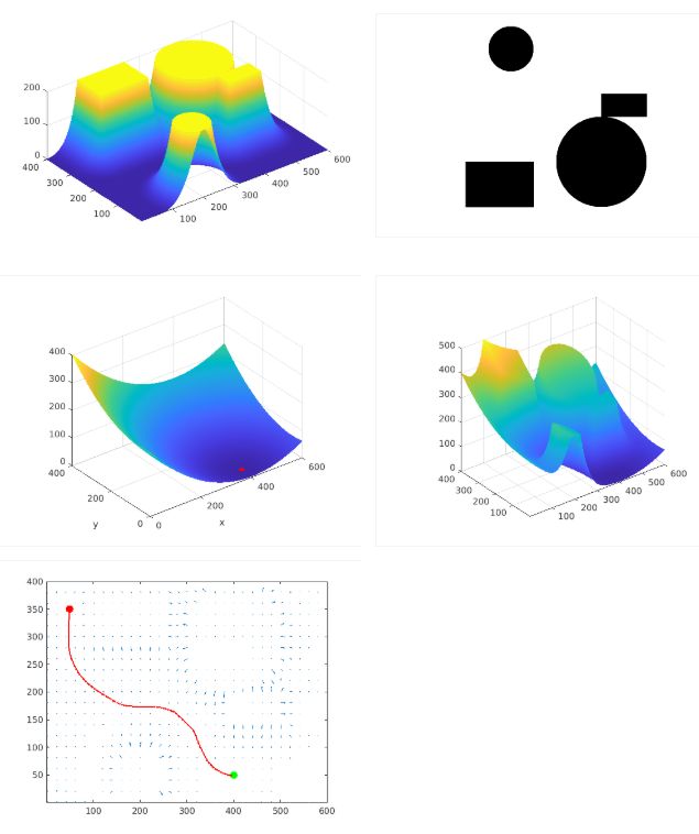
大家最好自己下载一下我贴的资源,是完整的题目,这样能看到过程,例如下图的过程:
UP主 博主自己做的字幕版本 第二单元打算都更
