路径规划与避障算法(六)---DWA算法流程之二---自行车模型与路径采样空间
版权声明:本文为博主原创文章,原创不易, 转载请联系博主。
本篇博客主要介绍如何生成速度采样空间以及利用车辆运动学模型生成对应的轨迹空间
1.运动学模型
车辆运动学模型与动力学模型的建立是出于车辆运动的规划与控制考虑的。自动驾驶场景下,车辆大多按照规划轨迹行驶,控制模块的作用就是控制车辆尽可能精准的按照规划轨迹行驶。这就要求规划轨迹尽可能贴近实际情况,也就是说,轨迹规划过程中应尽可能考虑车辆运动学及动力学约束,使得运动跟踪控制的性能更好。
在使用自行车模型之前也需要考虑以下三点假设 [1]:
- 车辆在垂直方向的运动被忽略掉了,也就是说我们描述的车辆是一个二维平面上的运动物体(可以等价与我们是站在天空中的俯视视角)
- 我们假设车辆的结构就像自行车一样,也就是说车辆的前面两个轮胎拥有一直的角度和转速等,同样后面的两个轮胎也是如此,那么前后的轮胎就可以各用一个轮胎来描述
- 我们假设车辆运动也和自行车一样,这意味着是前面的轮胎控制这车辆的转角

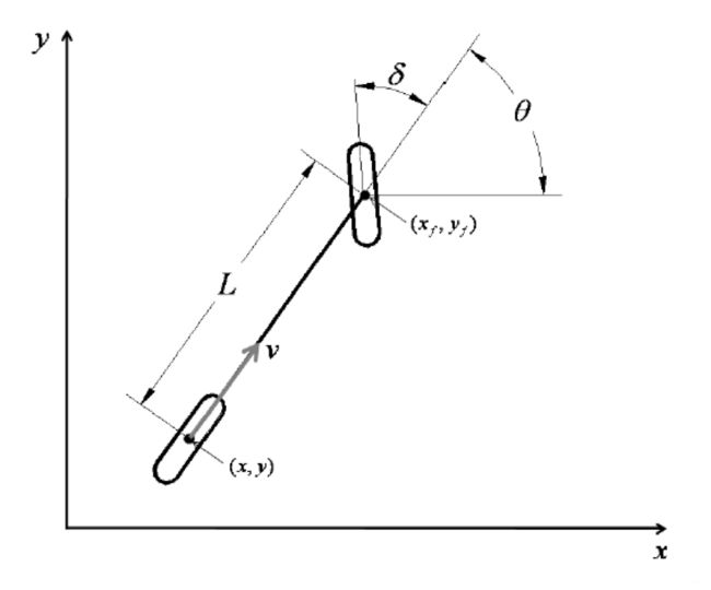
如上图所示,自行车运动学模型将前后轮胎分别用一个轮胎来描述并且将轮胎置于前后中心线上。假定车轮没有横向漂移且只有前向车轮是可以转向的。
公式推导
限制该模型在平面上运动,前后轮的非完整约束方程为:
(1) x ˙ f sin ( θ + δ ) − y ˙ cos ( θ + δ ) = 0 \dot{x}_f\sin(\theta+\delta)-\dot{y}\cos({\theta+\delta}) = 0\tag{1} x˙fsin(θ+δ)−y˙cos(θ+δ)=0(1)
(2) x ˙ sin ( θ ) − y ˙ cos ( θ ) = 0 \dot{x}\sin(\theta)-\dot{y}\cos(\theta) = 0\tag{2} x˙sin(θ)−y˙cos(θ)=0(2)
其中 ( x , y ) (x,y) (x,y) 是后轮的全局坐标, ( x f , y f ) (x_f,y_f ) (xf,yf)是前轮的全局坐标, θ θ θ是车辆在 y a w yaw yaw方向的偏转角度, δ δ δ是车辆的转向角度。由于车轮距离(前后轮胎之间的距离)为 L L L,因此 ( x f , y f ) (x_f,y_f ) (xf,yf)可以表示为:
(3) x f = x + L cos ( θ ) x_f = x+L\cos(\theta)\tag{3} xf=x+Lcos(θ)(3)
(4) y f = y + L sin ( θ ) y_f = y +L\sin(\theta) \tag{4} yf=y+Lsin(θ)(4)
将公式3以及公式4带入公式1中消除 ( x f , y f ) : (x_f,y_f): (xf,yf):
(5) 0 = x ˙ sin ( θ + δ ) − y ˙ cos ( θ + δ ) − θ ˙ L cos ( δ ) 0=\dot{x}\sin(\theta+\delta)-\dot{y}\cos(\theta+\delta)-\dot{\theta}L\cos(\delta)\tag{5} 0=x˙sin(θ+δ)−y˙cos(θ+δ)−θ˙Lcos(δ)(5)
( x ˙ , y ˙ ) (\dot{x},\dot{y}) (x˙,y˙)可以通过纵向速度 v v v来表示:
(6) x ˙ = v cos ( θ ) \dot{x} = v\cos(\theta)\tag{6} x˙=vcos(θ)(6)
(7) y ˙ = v sin ( θ ) \dot{y}=v\sin{(\theta)}\tag{7} y˙=vsin(θ)(7)
将公式6,7的限制条件应用于公式5可以得到 θ ˙ \dot{\theta} θ˙
(8) θ ˙ = v tan ( δ ) / L \dot{\theta}= v\tan(\delta)/L\tag{8} θ˙=vtan(δ)/L(8)
车辆的瞬时曲率半径 R R R是由 v v v以及 θ ˙ \dot\theta θ˙来决定的:
(9) R = v / θ ˙ R=v/\dot\theta\tag{9} R=v/θ˙(9)
结合公式8可得:
(10) tan ( δ ) = L / R \tan(\delta)=L/R\tag{10} tan(δ)=L/R(10)
最终以上运动学模型可以通过矩阵形式表达出来:
(11) [ x ˙ y ˙ θ ˙ v δ ˙ ] = [ cos θ sin θ ( tan ( δ ) / L ) 1 0 ] v + [ 0 0 0 0 1 ] δ ˙ \left[ \begin{matrix} \dot{x} \\ \dot{y} \\ \dot{\theta}\\ v\\ \dot{\delta} \end{matrix} \right] = \left[ \begin{matrix} \cos{\theta} \\ \sin{\theta} \\ (\tan(\delta)/L)\\ 1\\ 0 \end{matrix} \right]v+ \left[ \begin{matrix} 0 \\ 0 \\ 0 \\ 0\\ 1 \end{matrix} \right] \dot{\delta}\tag{11} ⎣⎢⎢⎢⎢⎡x˙y˙θ˙vδ˙⎦⎥⎥⎥⎥⎤=⎣⎢⎢⎢⎢⎡cosθsinθ(tan(δ)/L)10⎦⎥⎥⎥⎥⎤v+⎣⎢⎢⎢⎢⎡00001⎦⎥⎥⎥⎥⎤δ˙(11)
其中, v v v和 δ ˙ \dot{\delta} δ˙分别代表车辆的纵向速度以及转向轮的角速度。
[1]: https://blog.csdn.net/adamshan/article/details/78696874
样例代码(c++)
Eigen::Vector3f computeNewPositions( const Eigen::Vector3f &pos,
                    				 const Eigen::Vector3f &vel,
                    				 double dt)
{
  Eigen::Vector3f new_pos = Eigen::Vector3f::Zero();

  new_pos[0] = pos[0] + (vel[0] * cos(pos[2])) * dt;
  new_pos[1] = pos[1] + (vel[0] * sin(pos[2])) * dt;
  new_pos[2] = pos[2] + vel[2] * dt;
  return new_pos;
}
2.速度采样
车辆的运动学模型有了,根据速度就可以推算出车辆的运动轨迹。因此只需要采样很多速度,推算轨迹,然后根据代价函数评估所得的轨迹选出最优轨迹。
在DWA算法中,速度如何采样是一个极其重要的核心:在速度 ( v , δ ˙ ) (v,\dot{\delta}) (v,δ˙)的二维空间中,存在无穷多组速度,因此也存在无穷多组运动轨迹。但是根据车辆本身的运动学限制和环境限制可以将采样速度控制在一定的范围内:
- 车辆受自身最大速度以及最小速度的限制:
(12) V 1 = { ( v , δ ˙ ) ∣ v ∈ [ v m i n , v m a x ] , δ ˙ ∈ [ δ ˙ m i n , δ m a x ] } V_1=\{(v,\dot\delta)|v\in[v_{min},v_{max}],\dot{\delta}\in[\dot\delta_{min},\delta_{max}]\}\tag{12} V1={(v,δ˙)∣v∈[vmin,vmax],δ˙∈[δ˙min,δmax]}(12)
- 车辆受发动机以及变速箱等性能影响:
由于发动机力矩有限制以及行驶道路上摩擦系数等外界环境影响,存在最大加速度限制,因此车辆前向模拟的周期内,存在一个动态窗口,在该窗口内的速度是车辆当前能够实际达到的速度:
(13) V 2 = { ( v , δ ˙ ) ∣ v ∈ [ v − v a ˙ Δ t , v + v b ˙ Δ t ] ∩ [ δ ˙ − δ a ¨ Δ t , v + δ b ¨ Δ t ] } V_2 = \{(v,\dot\delta)|v\in[v-\dot{v_a}\Delta t,v+\dot{v_b}\Delta t] \cap [\dot\delta-\ddot{\delta_a}\Delta t,v+\ddot{\delta_b}\Delta t] \} \tag{13} V2={(v,δ˙)∣v∈[v−va˙Δt,v+vb˙Δt]∩[δ˙−δa¨Δt,v+δb¨Δt]}(13)
其中, v a ˙ , v b ˙ \dot{v_a},\dot{v_b} va˙,vb˙分别表示最大减速度与最大加速度; δ a ¨ , δ b ¨ \ddot{\delta_a},\ddot{\delta_b} δa¨,δb¨分别表示角速度的最大减速度与最大加速度。
针对以上两条准则生成的速度 V 1 , V 2 V_1,V_2 V1,V2进行交集处理 ( V 3 = V 1 ∩ V 2 ) (V_3=V_1\cap V_2) (V3=V1∩V2)并将处理后的速度集合 V 3 V_3 V3作为采样的有效范围区间。为了简化每组速度对应轨迹的计算,DWA算法假设车辆在往前模拟的这段时间内速度不变,直到下一时刻采样给定新的速度命令。
样例代码(c++)
void GenerateVelocity(
    const Eigen::Vector3f &pos,
    const Eigen::Vector3f &vel,
    const Eigen::Vector3f &goal,
    LocalPlannerLimits *limits,
    const Eigen::Vector3f &vsamples,
    bool discretize_by_time)
{
  /*
   * We actually generate all velocity sample vectors here, from which to generate trajectories later on
   */

  double max_vel_th = limits->max_rot_vel;
  double min_vel_th = limits->min_rot_vel;
  discretize_by_time_ = discretize_by_time;
  Eigen::Vector3f acc_lim = limits->getAccLimits();
  pos_ = pos;
  vel_ = vel;
  limits_ = limits;
  next_sample_index_ = 0;
  sample_params_.clear();

  double min_vel_x = limits->min_vel_x;
  double max_vel_x = limits->max_vel_x;
  double min_vel_y = limits->min_vel_y;
  double max_vel_y = limits->max_vel_y;

  // if sampling number is zero in any dimension, we don't generate samples generically
  if (vsamples[0] * vsamples[1] * vsamples[2] > 0)
  {
    //compute the feasible velocity space based on the rate at which we run
    Eigen::Vector3f max_vel = Eigen::Vector3f::Zero();
    Eigen::Vector3f min_vel = Eigen::Vector3f::Zero();

    max_vel[0] = std::min(max_vel_x, vel[0] + acc_lim[0] * sim_period_);
    max_vel[1] = 0.0;
    max_vel[2] = std::min(max_vel_th, vel[2] + acc_lim[2] * sim_period_);

    min_vel[0] = std::max(min_vel_x, vel[0] - acc_lim[0] * sim_period_);
    min_vel[1] = 0.0;
    min_vel[2] = std::max(min_vel_th, vel[2] - acc_lim[2] * sim_period_);


    Eigen::Vector3f vel_samp = Eigen::Vector3f::Zero();
    VelocityIterator x_it(min_vel[0], max_vel[0], vsamples[0]);
    VelocityIterator y_it(min_vel[1], max_vel[1], vsamples[1]);
    VelocityIterator th_it(min_vel[2], max_vel[2], vsamples[2]);
    for (; !x_it.isFinished(); x_it++)
    {
      vel_samp[0] = x_it.getVelocity();
      //cout << "vel_x: " << vel_samp[0] << endl;
      for (; !y_it.isFinished(); y_it++)
      {
        vel_samp[1] = y_it.getVelocity();
        //cout << "vel_y: " << vel_samp[1] << endl;
        for (; !th_it.isFinished(); th_it++)
        {
          vel_samp[2] = th_it.getVelocity();
          //cout << "vel_th: " << vel_samp[2] << endl;
          sample_params_.push_back(vel_samp);
        }
        th_it.reset();
      }
      y_it.reset();
    }
  }
}
下部分将会介绍DWA具体流程中:具体的路径评价函数