nRF52840作为通信模块与Arduino的联动
蓝牙控制Arduino板上13号引脚灯的开关
-
开发环境及工具
-
nRF52840的代码烧录
-
Arduino的测试代码
-
固件连接
-
手机蓝牙端测试
开发环境及工具
| 名称 | |
|---|---|
| 开发工具 | Segger Embedded Studio |
| SDK版本 | nRF5_SDK_15.3.0_59ac345 |
| 开发板 | IK-nRF52840DK+Arduino Uno+IO扩展板 |
| J-link | ARM-V9仿真器 |
| 手机App | nRF UART v2.0 |
nRF52840的代码烧录
打开SKD中示例的ble_app_uart,路径:E:\nRF5_SDK_15.3.0_59ac345\examples\ble_peripheral\ble_app_uart\pca10056\s140\ses
在main函数中将循环实例修改
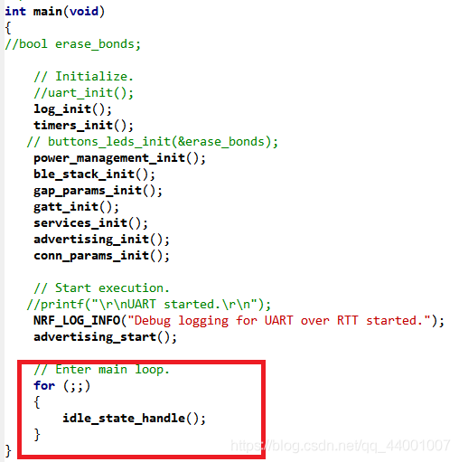
红圈里的修改为:
   while (true)
    {
        uint8_t cr;
        while (app_uart_get(&cr) != NRF_SUCCESS);
        while (app_uart_put(cr) != NRF_SUCCESS);

        if (cr == 'q' || cr == 'Q')
        {
            printf(" \r\nExit!\r\n");

            while (true)
            {           }
        }
    }
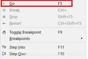
然后Build,Debug

Arduino的测试代码
将测试代码刷入Arduino就行了:char ss;
void setup(){
Serial.begin(115200);
pinMode(13,OUTPUT);
}
void loop(){
if(Serial.available()){
ss=Serial.read();
Serial.println(ss);
if(ss=='1')
digitalWrite(13,HIGH);
else
digitalWrite(13,LOW);
}
}
固件连接
将nRF52840的P06号脚接到IO扩展板上的RX接口,然后将VCC和GND与IO扩展板相应位置连接,如下图:
然后Arduino板通上电。
手机蓝牙端测试
1.打开App搜索设备  连接_UART设备 2.发送测试数据字符1
然后板上13灯亮起
3.输入其他任意字符熄灭
