Matlab quiver函数用法 - 画矢量箭头图
提要:
quiver (x, y,u,v)在点(x,y)处画(u,v)所定义的向量箭头。x,y,u,v必须是维度和元素数都一样的矩阵。如果是一维数组的话,x,y,u,v的元素数必须一致。quiver函数会自动调整箭头的长度以适应显示quiver(x,y,u,v,scale)scale 用于限定箭头的长度,如果scale = 1 则等值显示矢量的长度,而scale = 0.2 则显示0.2倍的矢量长度。quiver(u,v)在x-y平面上均匀地画箭头图quiver(x,y,u,v,LinSpec)用于限定箭头的属性,比如颜色,线型等。
quiver用于画矢量函数的箭头图(也叫速度图)(quiver plot, velocity vector plot)
举一个矢量函数的例子:
F ⃗ = i ⃗ x + j ⃗ y \vec{F}=\vec{i}x+\vec{j}y F=ix+jy
如下图,你可以把这个函数看作位置矢量 r ⃗ \vec{r} r,图中每一个箭头的方向都是向径(即从原点出发的一条直线),并且它的长度等于它到原点的距离。

quiver (x, y,u,v)在点(x,y)处画(u,v)所定义的向量箭头。x,y,u,v必须是维度和元素数都一样的矩阵。如果是一维数组的话,x,y,u,v的元素数必须一致。quiver函数会自动调整箭头的长度以适应显示。
%%  draw the velocity vector arrow of the vector function  i*x + j*y
% generate grids in a sub-definition area
clc
x = -1:0.5:1;
y = -1:0.5:1;

% generate the function values
u = x;
v = y;

% draw vector arrow graph
quiver(x, y, u, v)
text(0.5, 0, '$\leftarrow \vec{F}=\vec{i}x + \vec{j}y $', 'HorizontalAlignment', 'left', 'Interpreter', 'latex', 'FontSize', 15);
grid on
axis equal

quiver(x,y,u,v,scale)scale 用于限定箭头的长度,如果scale = 1 则等值显示矢量的长度,而scale = 0.2 则显示0.2倍的矢量长度。比如以上的代码,若加入scale参数,则输出图像如下:
%%  draw the velocity vector arrow of the vector function  i*x + j*y
% generate grids in a sub-definition area
clc
x = -1:0.5:1;
y = -1:0.5:1;

% generate the function values
u = x;
v = y;

% draw vector arrow graph
scale = 0.2
quiver(x, y, u, v,scale)
text(0.5, 0, '$\leftarrow \vec{F}=\vec{i}x + \vec{j}y $', 'HorizontalAlignment', 'left', 'Interpreter', 'latex', 'FontSize', 15);
grid on
axis equal
quiver(u,v)在x-y平面上均匀地画箭头图
比如函数 F ⃗ = − i ⃗ y + j ⃗ x x 2 + y 2 \vec{F}=\frac{ -\vec{i}y+\vec{j}x}{\sqrt{x^{2}+y^{2}} } F=x2+y2−iy+jx 使用quiver(x,y,u,v,scale)书写代码:
%%  draw the velocity vector arrow of the vector function  (i*y + j*x)/sqrt(x^2 + y^2)
% generate grids in a sub-definition area
clc

R = 2:2:6;
theta = -pi:pi/4:pi;
x = R'*cos(theta);
y = R'*sin(theta);

% generate the function values
rr = sqrt(x.^2 + y.^2);
fx = -y./rr;
fy = x./rr;
%[FX,FY] = meshgrid(fx,fy);

% draw vector arrow graph
scale = 0.2;
quiver(x, y, fx, fy,scale)
text(4, 2, '$\vec{F}=\frac{ -\vec{i}y+\vec{j}x}{\sqrt{x^{2}+y^{2}} } $', 'HorizontalAlignment', 'left', 'Interpreter', 'latex', 'FontSize', 15);
grid on
axis equal
输出的图像为

而我们用quiver(u,v)替换掉quiver(x,y,u,v,scale),代码变为:
%%  draw the velocity vector arrow of the vector function  (i*y + j*x)/sqrt(x^2 + y^2)
% generate grids in a sub-definition area
clc

R = 2:2:6;
theta = -pi:pi/4:pi;
x = R'*cos(theta);
y = R'*sin(theta);

% generate the function values
rr = sqrt(x.^2 + y.^2);
fx = -y./rr;
fy = x./rr;
%[FX,FY] = meshgrid(fx,fy);

% draw vector arrow graph
scale = 0.2;
quiver(fx, fy,scale)
text(4, 2, '$\vec{F}=\frac{ -\vec{i}y+\vec{j}x}{\sqrt{x^{2}+y^{2}} } $', 'HorizontalAlignment', 'left', 'Interpreter', 'latex', 'FontSize', 15);
grid on
axis equal
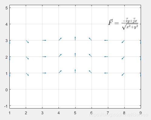
输出的箭头图不再是环形分布,而变成x-y平面上的均匀分布:

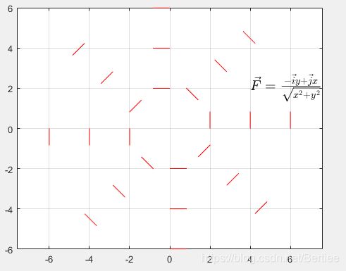
quiver(x,y,u,v,LinSpec)用于限定箭头的属性,比如颜色,线型等。
示例代码:
%%  draw the velocity vector arrow of the vector function  (i*y + j*x)/sqrt(x^2 + y^2)
% generate grids in a sub-definition area
clc

R = 2:2:6;
theta = -pi:pi/4:pi;
x = R'*cos(theta);
y = R'*sin(theta);

% generate the function values
rr = sqrt(x.^2 + y.^2);
fx = -y./rr;
fy = x./rr;
%[FX,FY] = meshgrid(fx,fy);

% draw vector arrow graph
scale = 0.2;
quiver(x, y, fx, fy,scale,'.r')
text(4, 2, '$\vec{F}=\frac{ -\vec{i}y+\vec{j}x}{\sqrt{x^{2}+y^{2}} } $', 'HorizontalAlignment', 'left', 'Interpreter', 'latex', 'FontSize', 15);
grid on
axis equal


