Pixel-level Extrinsic Self Calibration of High Resolution LiDAR and Camera in Targetless Environment
目录
- Pixel-level Extrinsic Self Calibration of High Resolution LiDAR and Camera in Targetless Environments
-
- Abstract
- 1.Introduction
- 2.Related Works
- 3.Method
-
- A. Overview
- B. Edge Extraction and Matching
-
- 1) Edge Extraction:
- 2) Matching:
- C. Extrinsic Calibration
-
- 1) Measurement noises:
- 2) Calibration Formulation and Optimization:
- 3) Calibration Uncertainty:
- D. Analysis of Edge Distribution on Calibration Result
- E. Initialization and Rough Calibration
- 4.EXPERIMENTS AND RESULTS
-
- A. Calibration Results in Outdoor and Indoor Scenes
-
- 1) Robustness and Convergence Validation:
- 2) Consistency Evaluation:
- 3) Cross Validation:
- 4) Bad Scenes:
- B. Comparison Experiments
- C. Applicability to Other Types of LiDARs
- 5.Conclusion
Pixel-level Extrinsic Self Calibration of High Resolution LiDAR and Camera in Targetless Environments
Abstract
In this letter, we present a novel method for automatic extrinsic calibration of high-resolution LiDARs and RGB cameras in targetless environments. Our approach does not require checkerboards but can achieve pixel-level accuracy by aligning natural edge features in the two sensors. On the theory level, we analyze the constraints imposed by edge features and the sensitivity of calibration accuracy with respect to edge distribution in the scene. On the implementation level, we carefully investigate the physical measuring principles of LiDARs and propose an efficient and accurate LiDAR edge extraction method based on point cloud voxel cutting and plane fitting. Due to the edges’ richness in natural scenes, we have carried out experiments in many indoor and outdoor scenes. The results show that this method has high robustness, accuracy, and consistency. It can promote the research and application of the fusion between LiDAR and camera. We have open sourced our code on GitHub1 to benefit the community.
在本篇论文中,我们提出了一种在无目标环境中自动校准高分辨率激光和RGB相机外参的新方法。我们的方法不需要棋盘格,但可以通过对齐两个传感器中的自然边缘特征( natural edge features)来实现像素级精度。在理论层面上,我们分析了边缘特征施加的约束以及标定精度对场景中边缘分布的敏感性。在实现层面,我们仔细研究了激光雷达的物理测量原理,提出了一种基于点云体素切割和平面拟合的高效、准确的激光雷达边缘提取方法。由于自然场景中边缘的丰富性,我们在许多室内和室外场景中进行了实验。结果表明,该方法具有较高的鲁棒性、准确性和一致性。它可以促进激光雷达与相机融合的研究和应用。我们已经在GitHub上公开了我们的代码。
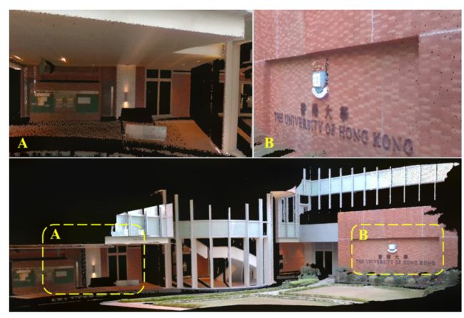
Fig. 1: Point cloud of three aligned LiDAR scans colored using the proposed method. The accompanying experiment video has been uploaded to https://youtu.be/e6Vkkasc4JI
图1:使用提出的方法对三个对齐的激光雷达扫描进行着色的点云。实验视频已上传至https://youtu.be/e6Vkkasc4JI
代码:https://github.com/hku-mars/livox_camera_calib
文章: https://arxiv.org/pdf/2103.01627.pdf
怎么提取激光和相机的自然边缘特征?3.B.(2)
激光边缘特征: 我们首先将点云划分为指定大小的体素(voxels)0.5m)。再使用RANSAC拟合和提取体素中包含的平面。然后,我们保留在一定范围内连接并形成角度的平面对,并求解平面相交线(即深度连续边)
对于图像边缘提取,我们使用Canny算法[19]。提取的边缘像素保存在k-D tree(k=2)中,用于对应匹配
什么是 canny算法?
https://blog.csdn.net/saltriver/article/details/80545571
核心思想在于计算图像梯度+非极大值抑制
什么是k-D tree?
https://blog.csdn.net/qq_39747794/article/details/82262576
激光和相机的自然边缘特征怎么匹配?
在激光边缘采样多个点,基于初始外参转换到相机坐标系下,在通过相机内参投影到像素坐标系,图像边缘像素构建的k-D树中搜索该投影点的最近邻
粗校准和精校准的区别?
粗校准:最大化边缘对应百分比,匹配基于激光雷达边缘点(投影到图像平面后)到图像中最近边缘的距离和方向。
精校准就是论文的方
标定用时?
我们的整个pipeline,包括特征提取,匹配,粗略校准和精细校准,只需不到60秒
体素是正方形的吗?提取的面是垂直的吗?法线为(1,0,0),d为-origin[0]的面是垂直于x轴的voxel的面吗?
体素是正方体的,提取的面是体素区域中各种方向的面,法线为(1,0,0),d为-origin[0]的面是垂直于x轴的voxel的面。
目的是为了在体素中确定滤波出的两个面交线在体素中的两个点。
1.Introduction
Light detection and ranging (LiDAR) and camera sensors are commonly combined in developing autonomous driving vehicles. LiDAR sensor, owing to its direct 3D measurement capability, has been extensively applied to obstacle detection [1], tracking [2], and mapping [3] applications. The integrated onboard camera could also provide rich color information and facilitate the various LiDAR applications. With the recent rapid growing resolutions of LiDAR sensors, the demand for accurate extrinsic parameters becomes essential, especially for applications such as dense point cloud mapping, colorization, and accurate and automated 3D surveying. In this letter, our work deals with the accurate extrinsic calibration of high-resolution LiDAR and camera sensors.
LiDAR和相机传感器通常组合应用在自动驾驶车辆中。激光雷达传感器由于其直接的三维测量能力,已广泛应用于障碍物检测[1],跟踪[2]和测绘[3]应用。集成的车载摄像机还可以提供丰富的色彩信息,促进各种激光雷达应用。随着最近激光雷达传感器分辨率的快速增长,对精确外参的需求变得至关重要,特别是对于密集点云映射,着色以及准确自动3D测量等应用。在这篇论文中,我们的工作涉及高分辨率激光雷达和相机传感器的精确外参校准。
Current extrinsic calibration methods rely heavily on external targets, such as checkerboard [4]–[6] or specific image pattern [7]. By detecting, extracting, and matching feature points from both image and point cloud, the original problem is transformed into and solved with least-square equations. Due to its repetitive scanning pattern and the inevitable vibration of mechanical spinning LiDAR, e.g., Velodyne2, the reflected point cloud tends to be sparse and of large noise. This characteristic may mislead the cost function to the unstable results. Solid-state LiDAR, e.g., Livox [8], could compensate for this drawback with its dense point cloud. However, since these calibration targets are typically placed close to the sensor suite, the extrinsic error might be enlarged in the long-range scenario, e.g., large-scale point cloud colorization. In addition, it is not always practical to calibrate the sensors with targets being prepared at the start of each mission.
当前的外参校准方法严重依赖于外部目标,如棋盘[4]–[6]或特定图案[7]。通过从图像和点云中检测、提取和匹配特征点,将原始问题转化为最小二乘方程组求解。由于重复扫描模式和机械旋转激光雷达(如Velodyne2)不可避免的振动,反射点云往往稀疏且噪声大。这一特点可能会使成本函数产生不稳定的结果。固态激光雷达,例如Livox[8],可以通过密集的点云来弥补这一缺陷。然而,由于这些校准目标通常放置在靠近传感器套件的位置,因此在长距离场景中,外部误差可能会增大,例如,大规模点云着色。此外,在每次任务开始时都用标定好的目标校准传感器不总是切实可行的。
To address the above challenges, in this letter, we propose an automatic pixel-level extrinsic calibration method in targetless environments. This system operates by extracting natural edge features from the image and point cloud and minimizing the reprojection error. The proposed method does not rely on external targets, e.g., checkerboard, and is capable of functioning in both indoor and outdoor scenes. Such a simple and convenient calibration allows one to calibrate the extrinsic parameters before or in the middle of each data collection or detect any misalignment of the sensors during their online operation that is usually not feasible with the target-based methods. Specifically, our contributions are as follows:
为了解决上述挑战,在本次论文中,我们提出了一种无目标(targetless)环境下的自动的像素级外参校准方法。该系统通过从图像和点云中提取自然边缘特征并最小化重投影误差来运行。所提出的方法不依赖于外部目标,例如棋盘,并且能够在室内和室外场景中工作。这种简单且方便的校准允许人们在每个数据收集之前或中间校准外参,或者在传感器的运行过程中检测它们的失准,这通常是基于目标(target-base)的方法做不到的。具体而言,我们的贡献如下:
• We carefully study the underlying LiDAR measuring principle, which reveals that the commonly used depthdiscontinuous edge features are not accurate nor reliable for calibration. We propose a novel and reliable depthcontinuous edge extraction algorithm that leads to more accurate calibration parameters.
• We evaluate the robustness, consistency, and accuracy of our methods and implementation in various indoor and outdoor environments and compare our methods with other state-of-the-art. Results show that our method is robust to initial conditions, consistent to calibration scenes, and achieves pixel-level calibration accuracy in natural environments. Our method has an accuracy that is on par to (and sometimes even better than) target-based methods and is applicable to both emerging solid-state and conventional spinning LiDARs.
• Based on the analysis, we develop a practical calibration software and open source it on GitHub to benefit the community.
• 我们仔细研究了激光雷达的基本测量原理,结果表明,常用的深度不连续边缘特征对于校准来说既不准确也不可靠。我们提出了一种新的、可靠的深度连续边缘提取算法,该算法可以获得更精确的校准参数。
• 我们评估了我们的方法和实现在各种室内外环境中的健壮性、一致性和准确性,并将我们的方法与其他最先进的方法进行了比较。结果表明,该方法对初始条件具有鲁棒性,与标定场景一致,在自然环境中达到了像素级标定精度。我们的方法具有精确的精度(有时甚至优于基于目标的方法),并且适用于新兴的固态和传统旋转激光雷达。
• 在此基础上,我们开发了一个实用的校准软件,并在GitHub上开放源代码,以造福社区。
2.Related Works
Extrinsic calibration is a well-studied problem in robotics and is mainly divided into two categories: target-based and targetless. The primary distinction between them is how they define and extract features from both sensors. Geometric solids [9]–[11] and checkerboards [4]–[6] have been widely applied in target-based methods, due to its explicit constraints on plane normals and simplicity in problem formulation. As they require extra preparation, they are not practical, especially when they need to operate in a dynamically changing environment.
外参校准是机器人学中一个研究得很好的问题,主要分为两类:基于目标的和无目标的。它们之间的主要区别在于如何定义和提取两个传感器的特征。几何实体[9]–[11]和棋盘[4]–[6]由于其对平面法线的明确约束和问题公式的简单性,已广泛应用于基于目标的方法中。因为它们需要额外的准备,所以不实用,特别是当它们需要在动态变化的环境中运行时。
Targetless methods do not detect explicit geometric shapes from known targets. Instead, they use the more general plane and edge features that existed in nature. In [12], the LiDAR points are first projected onto the image plane and colored by depth and reflectivity values. Then 2D edges are extracted from this colormap and matched with those obtained from the image. Similarly, authors in [13] optimize the extrinsic calibration by maximizing the mutual information between the colormap and the image. In [14, 15], both authors detect and extract 3D edges from the point cloud by laser beam depth discontinuity. Then the 3D edges are back-projected onto the 2D image plane to calculate the residuals. The accuracy of edge estimation limits this method as the laser points do not strictly fall on the depth discontinuity margin. Motion-based methods have also been introduced in [16, 17] that the extrinsic is estimated from sensors’ motion and refined by appearance information. This motion-based calibration typically requires the sensor to move along a sufficient excited trajectory [17].
无目标方法无法检测已知目标的显式几何形状。相反,它们使用自然界中存在的更一般的平面和边缘特征。在[12]中,激光雷达点首先投影到图像平面上,并通过深度和反射率值着色。然后从该彩色地图中提取二维边缘,并与从图像中获得的边缘进行匹配。类似地,[13]中的作者通过最大化彩色贴图和图像之间的互信息来优化外部校准。在[14,15]中,两位作者都通过激光束深度不连续性从点云中检测和提取3D边缘。然后将3D边反向投影到2D图像平面上,以计算残差。由于激光点不严格落在深度不连续边界上,边缘估计的精度限制了该方法。[16,17]中还介绍了基于运动的方法,即根据传感器的运动估计外部信息,并通过外观信息进行细化。这种基于运动的校准通常需要传感器沿着足够的激励轨迹移动[17]。
Our proposed method is a targetless method. Compared to [12, 13], we directly extract 3D edge features in the point cloud, which suffer from no occlusion problem. Compared to [14, 15], we use depth-continuous edges, which proved to be more accurate and reliable. Our method works for a single pair LiDAR scan and achieves calibration accuracy comparable to target-based methods [4, 6].
我们提出的方法是一种无目标的方法。与[12,13]相比,我们直接在点云中提取3D边缘特征,不存在遮挡问题。与[14,15]相比,我们使用了深度连续边,这被证明更加准确和可靠。我们的方法适用于单对激光雷达扫描,并达到与基于目标的方法相当的校准精度[4,6]。
3.Method
A. Overview
Fig. 2 defines the coordinate frames involved in this paper: the LiDAR frame L, the camera frame C, and the 2D coordinate frame in the image plane. Denote L C T = ( L C R , L C T ) ∈ S E ( 3 ) ^C_LT=(^C_LR,^C_LT)∈ SE(3) LCT=(LCR,LCT)∈SE(3) the extrinsic between LiDAR and camera to be calibrated. Due to the wide availability of edge features in natural indoor and outdoor scenes, our method aligns these edge features observed by both LiDAR and camera sensors. Fig. 2 further illustrates the number of constraints imposed by a single edge to the extrinsic. As can be seen, the following degree of freedom (DoF) of the LiDAR pose relative to the camera cannot be distinguished: (1) translation along the edge (the red arrow D, Fig. 2), (2) translation perpendicular to the edge (the green arrow C, Fig. 2), (3) rotation about the normal vector of the plane formed by the edge and the camera focal point (the blue arrow B, Fig. 2), and (4) rotation about the edge itself (the purple arrow A, Fig. 2). As a result, a single edge feature constitutes two effective constraints to the extrinsic L C T ^C_LT LCT. To obtain sufficient constraints to the extrinsic, we extract edge features of different orientations and locations, as detailed in the following section.
图2定义了本文涉及的坐标帧:激光雷达坐标系L、相机坐标系C和图像平面中的2D坐标系。定义 L C T = ( L C R , L C T ) ∈ S E ( 3 ) ^C_LT=(^C_LR,^C_LT)∈ SE(3) LCT=(LCR,LCT)∈SE(3)为激光雷达和相机之间的需要标定的外参。由于在自然室内和室外场景中边缘特征的广泛可用性,我们的方法将激光雷达和相机传感器观察到的这些边缘特征对齐。图2进一步表示了单条边可以施加给外参的约束的数量。可以看出,相对于相机的激光姿态的以下自由度(DoF)是无法区分的:(1)沿边缘平移(红色箭头D,图2),(2)垂直于边缘平移(绿色箭头C,图2),(3)围绕边缘和相机焦点形成的平面法向量旋转(蓝色箭头B,图2)和(4)围绕边缘本身旋转(紫色箭头A,图2)。因此,单个边缘特征构成了外参 L C T ^C_LT LCT的两个有效约束。为了获得外参的充分约束,我们提取了不同方向和位置的边缘特征,详见下一节。
一条激光边缘线对应两个自由度
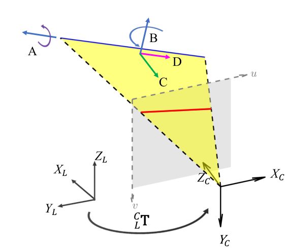
Fig. 2: Constraints imposed by an edge feature. The blue line represents the 3D edge, its projection to the image plane (the gray plane) produces the camera measurement (the red line). The edge after a translation along the axis C or axis D, or a rotation about the axis A (i.e., the edge itself) or axis B (except when the edge passes through the camera origin), remains on the same yellow plane and hence has the same projection on the image plane. That means, these four pose transformations on the edge (or equivalently on L C T ^C_LT LCT) are not distinguishable.
图2:边缘特征施加的约束。蓝线表示3D边,其投影到图像平面(灰平面)产生相机测量值(红线)。沿轴C或轴D平移或围绕轴a(即,边缘本身)或轴B旋转(除非边缘穿过相机原点)后的边缘保持在相同的黄色平面上,因此在图像平面上具有相同的投影。这意味着,边上(或相当于 L C T ^C_LT LCT上)的这四个姿势变换是不可区分的。
B. Edge Extraction and Matching
1) Edge Extraction:
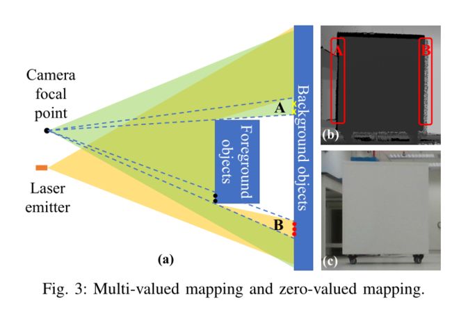
Some existing works project the point cloud to the image plane and extract features from the projected point cloud, such as edge extraction [12] and the mutual information correlation [13]. A major problem of the feature extraction after points projection is the multi-valued and zerovalued mapping caused by occlusion. As illustrated in Fig. 3 (a), if the camera is above the LiDAR, region A is observed by the camera but not LiDAR due to occlusion, resulting in no points after projection in this region (zero-valued mapping, the gap in region A, Fig. 3 (b)). On the other hand, region B is observed by the LiDAR but not the camera, points in this region (the red dots in Fig. 3 (a)) after projection will intervene the projection of points on its foreground (the black dots in Fig. 3 (a)). As a result, points of the foreground and background will correspond to the same image regions (multivalued mapping, region B, Fig. 3 (b)). These phenomenon may not be significant for LiDARs of low-resolution [13], but is evident in as the LiDAR resolution increases (see Fig. 3 (b)). Extracting features on the projected point clouds and match them to the image features, such as [13], would suffer from these fundamental problems and cause significant errors in edge extraction and calibration.
1) 边缘提取:一些现有工作将点云投影到图像平面,并从投影点云中提取特征,如边缘提取[12]和互信息关联( mutual information correlation)[13]。投影激光点后再进行特征提取的一个主要问题是遮挡引起的多值和零值映射。如图3(a)所示,如果摄像机位于激光雷达上方,则由于遮挡,摄像机可以观察到区域a,激光雷达则无法看到,从而在投影后该区域中是没有点的(零值映射,区域a中的gap,图3(b))。另一方面,激光可以观测到区域B,而相机无法观测到,投影后该区域中的点(图3(a)中的红点)将干涉其前景上点的投影(图3(a)中的黑点)。结果,前景和背景的点将都对应于相同的图像区域(多值映射,区域B,图3(B))。对于低分辨率的激光雷达而言,这些现象可能并不显著[13],但随着激光雷达分辨率的增加,这些现象变得明显(见图3(b))。在投影点云上提取特征并将其与图像特征相匹配(如[13])就会遇到这些基本问题,并在边缘提取和校准中造成重大误差。
To avoid the zero-valued and multi-valued mapping problem caused by projection, we extract edge features directly on the LiDAR point cloud. There are two types of edges: depth-discontinuous and depth-continuous. As shown in Fig. 4 (a), depth-discontinuous edges refer to edges between foreground objects and background objects where the depth jumps. In contrast, depth-continuous edges refer to the plane joining lines where the depth varies continuously. Many existing methods [14, 15] use the depth-discontinuous edges as they can be easily extracted by examining the point depth. However, carefully investigating the LiDAR measuring principle, we found that depth-discontinuous edges are not reliable nor accurate for high accuracy calibration. As shown in Fig. 5, a practical laser pulse is not an ideal point but a beam with a certain divergence angle (i.e., the beam divergence angle). When scanning from a foreground object to a background one, part of the laser pulse is reflected by the foreground object while the remaining reflected by the background, producing two reflected pulses to the laser receiver. In the case of the high reflectivity of the foreground object, signals caused by the first pulse will dominate, even when the beam centerline is off the foreground object, this will cause fake points of the foreground object beyond the actual edge (the leftmost yellow point in Fig. 5 (a)). In the case the foreground object is close to the background, signals caused by the two pulses will join, and the lumped signal will lead to a set of points connecting the foreground and the background (called the bleeding points, the yellow points in Fig. 5 (a)). The two phenomena will mistakenly inflate the foreground object and cause significant errors in the edge extraction (Fig. 5 (b)) and calibration.
为了避免投影引起的零值和多值映射问题,我们直接在激光雷达点云上提取边缘特征。有两种类型的边:深度不连续边和深度连续边。如图4(a)所示,深度不连续边指的是深度跳跃的前景对象和背景对象之间的边。相反,深度连续边指深度连续变化的平面连接线。许多现有方法[14,15]使用深度不连续边,因为它们可以通过检查点深度轻松提取。然而,仔细研究激光雷达测量原理,我们发现深度不连续边缘对于高精度校准既不可靠也不精确。如图5所示,实际激光脉冲不是理想点,而是具有一定发散角(即光束发散角)的光束。当从前景物体扫描到背景物体时,一部分激光脉冲被前景物体反射,其余部分被背景反射,产生两个反射脉冲到激光接收器。在前景对象的高反射率的情况下,由第一脉冲引起的信号将占主导地位,即使当光束中心线离开前景对象时,这将导致前景对象的伪点(fake points)超出实际边缘(图5(a)中最左侧的黄色点)。在前景物体接近背景的情况下,由两个脉冲引起的信号将合并,并且集中信号将导致连接前景和背景的一组点(称为出血(bleeding)点,图5(a)中的黄色点)。(使用深度不连续边时,)这两种现象将错误地使前景对象膨胀,并在边缘提取(图5(b))和校准中造成严重错误。
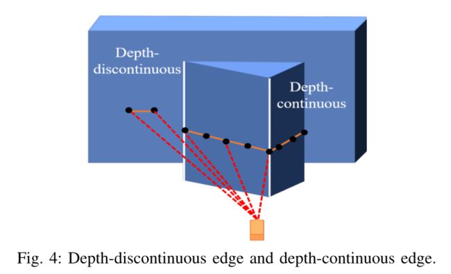
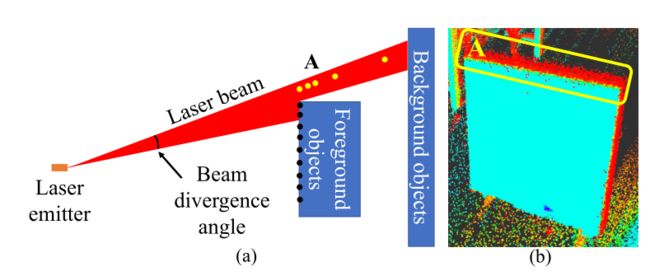
Fig. 5: Foreground objects inflation and bleeding points caused by laser beam divergence angle.
图5:由激光光束发散角引起的前景物体膨胀和bleeding点。
前景物体膨胀: 在前景对象的高反射率的情况下,由第一脉冲引起的信号将占主导地位,即使当光束中心线离开前景对象时,这将导致前景对象的伪点(fake points)超出实际边缘(图5(a)中最左侧的黄色点)。
bleeding points :在前景物体接近背景的情况下,由两个脉冲引起的信号将合并,并且集中信号将导致连接前景和背景的一组点(称为出血(bleeding)点,图5(a)中的黄色点)
To avoid the foreground inflation and bleeding points caused by depth-discontinuous edges, we propose to extracting depthcontinuous edges. The overall procedure is summarized in Fig. 6: we first divide the point cloud into small voxels of given sizes (e.g., 1m for outdoor scenes and 0.5m for indoor scenes). For each voxel, we repeatedly use RANSAC to fit and extract planes contained in the voxel. Then, we retain plane pairs that are connected and form an angle within a certain range (e.g., [30°,150°]) and solve for the plane intersection lines (i.e., the depth-continuous edge). As shown in Fig. 6, our method is able to extract multiple intersection lines that are perpendicular or parallel to each other within a voxel. Moreover, by properly choosing the voxel size, we can even extract curved edges.
为了避免由深度不连续边缘引起的前景膨胀和bleeding点,我们提出了提取深度连续边缘的方法。图6总结了整个过程:我们首先将点云划分为指定大小的小体素(voxels)(例如,室外场景为1m,室内场景为0.5m)。对于每个体素,我们反复使用RANSAC拟合和提取体素中包含的平面。然后,我们保留在一定范围内(例如,[30°、150°])连接并形成角度的平面对,并求解平面相交线(即深度连续边)。如图6所示,我们的方法能够提取体素内相互垂直或平行的多条相交线。此外,通过适当选择体素大小,我们甚至可以提取曲线边缘。

Fig. 6: Depth-continuous edge extraction. In each voxel grid, different colors represent different voxels. Within the voxel, different colors represent different planes, and the white lines represent the intersections between planes.
图6:深度连续边缘提取。在每个体素网格中,不同的颜色表示不同的体素。在体素中,不同的颜色表示不同的平面,白线表示平面之间的交线。
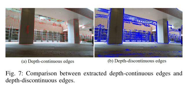
Fig. 7 shows a comparison between the extracted depthcontinuous and depth-discontinuous edges when overlaid with the image using correct extrinsic value. The depthdiscontinuous edge is extracted based on the local curvature as in [18]. It can be seen that the depth-continuous edges are more accurate and contain less noise.
图7显示了使用正确的外参并对图像重叠时提取的深度连续和深度不连续边缘之间的比较。根据局部曲率提取深度不连续边,如[18]所示。可以看出,深度连续边更精确,包含的噪声更少。
For image edge extraction, we use the Canny algorithm [19]. The extracted edge pixels are saved in a k-D tree (k = 2) for the correspondence matching.
对于图像边缘提取,我们使用Canny算法[19]。提取的边缘像素保存在k-D tree(k=2)中,用于对应匹配。
2) Matching:
The extracted LiDAR edges need to be matched to their corresponding edges in the image. For each extracted LiDAR edge, we sample multiple points on the edge. Each sampled point L P i ∈ R 3 ^LP_i∈ \mathbb{R^3} LPi∈R3 is transformed into the camera frame (using the current extrinsic estimate L C T = ( L C R , L C T ) ∈ S E ( 3 ) ^C_LT=(^C_LR,^C_LT)∈ SE(3) LCT=(LCR,LCT)∈SE(3))
2) 匹配:提取的激光雷达边缘需要与图像中相应的边缘匹配。对于每个提取的激光雷达边缘,我们在边缘上采样多个点。每个采样点 L P i ∈ R 3 ^LP_i∈ \mathbb{R^3} LPi∈R3(使用当前的外参估计值 L C T = ( L C R , L C T ) ∈ S E ( 3 ) ^C_LT=(^C_LR,^C_LT)∈ SE(3) LCT=(LCR,LCT)∈SE(3))转换到相机坐标系。

where L C T ‾ ( L P i ) = L C R ‾ ⋅ L P i + L C t ‾ { }_{L}^{C} \overline{\mathbf{T}}\left({ }^{L} \mathbf{P}_{i}\right)={ }_{L}^{C} \overline{\mathbf{R}} \cdot{ }^{L} \mathbf{P}_{i}+{ }_{L}^{C} \overline{\mathbf{t}} LCT(LPi)=LCR⋅LPi+LCt denotes applying the rigid transformation L C T { }_{L}^{C} \mathbf{T} LCT to point L P i { }^{L} \mathbf{P}_{i} LPi. The transformed point C P i { }^{C} \mathbf{P}_{i} CPi is then projected onto the camera image plane to produce an expected location C p i ∈ R 2 { }^{C} \mathbf{p}_{i} \in \mathbb{R}^{2} Cpi∈R2
其中 L C T ‾ ( L P i ) = L C R ‾ ⋅ L P i + L C t ‾ { }_{L}^{C} \overline{\mathbf{T}}\left({ }^{L} \mathbf{P}_{i}\right)={ }_{L}^{C} \overline{\mathbf{R}} \cdot{ }^{L} \mathbf{P}_{i}+{ }_{L}^{C} \overline{\mathbf{t}} LCT(LPi)=LCR⋅LPi+LCt表示将刚性变换 L C T { }_{L}^{C} \mathbf{T} LCT应用于点 L P i { }^{L} \mathbf{P}_{i} LPi。然后将变换后的点 C P i { }^{C} \mathbf{P}_{i} CPi 投影到相机图像平面上,以产生预期位置 C p i ∈ R 2 { }^{C} \mathbf{p}_{i} \in \mathbb{R}^{2} Cpi∈R2

where π§ is the pin-hole projection model. Since the actual camera is subject to distortions, the actual location of the projected point pi= (ui, vi) on the image plane is
其中π(P)是针孔投影模型。由于实际相机会产生畸变,投影点pi=(ui,vi)在图像平面上的实际位置是

where f ( p ) f(p) f(p) is the camera distortion model.
We search the κ nearest neighbor of p i p_i pi in the k-D tree built from the image edge pixels. Denotes Q i = { q i j ; j = 1 , ⋅ ⋅ ⋅ , κ } Qi= \{q^j_i ; j = 1,· · · , κ\} Qi={qij;j=1,⋅⋅⋅,κ} the κ nearest neighbours and
我们在由图像边缘像素构建的k-D树中搜索pi(激光投影点)的前κ个最近邻。定义 Q i = { q i j ; j = 1 , ⋅ ⋅ ⋅ , κ } Qi=\{q^j_i ; j = 1,· · · , κ\} Qi={qij;j=1,⋅⋅⋅,κ}为pi的前κ个最近的邻居(图像像素点?)

q i q_i qi表示前 k k k个 p i p_i pi最近邻的像素点的平均距离, n i n_i ni表示垂直与图像边缘方向的法向量(见图9(b)) S i S_i Si的意义是什么:像素点的协方差
Then, the line formed by Qi is parameterized by point qi lying on the line and the normal vector ni, which is the eigenvector associated to the minimal eigenvalue of Si.
然后,由Qi形成的线由位于该线上的点 q i q_i qi和法向量 n i n_i ni参数所确定,法向量ni是与Si的最小特征值对应的特征向量(与对大特征值对应的特征向量是直线的方向,与最小特征值对应的特征向量是垂直与直线的法向量)。
Besides projecting the point L P i ^LP_i LPi sampled on the extracted LiDAR edge, we also project the edge direction to the image plane and validate its orthogonality with respect to ni. This can effectively remove error matches when two non-parallel lines are near to each other in the image plane. Fig. 8 shows an example of the extracted LiDAR edges (red lines), image edge pixels (blue lines) and the correspondences (green lines).
除了将激光边缘上的采样点 L P i ^LP_i LPi投影之外,我们还将边缘方向投影到图像平面,并验证其与 n i n_i ni的正交性。可以有效减少两条接近的非平行直线的误匹配。图8示出了提取的LiDAR边缘(红线)、图像边缘像素(蓝线)和对应(绿线)的示例。

C. Extrinsic Calibration
1) Measurement noises:
The extracted LiDAR edge points L P i ^LP_i LPiand the corresponding edge feature (ni,qi) in the image are subject to measurement noises. Let I w i ∈ N ( 0 , I Σ i ) ^Iw_i ∈ N(0,^IΣ_i) Iwi∈N(0,IΣi) be the noise associated with qi during the image edge extraction, its covariance is I ∑ I = σ I 2 I 2 × 2 ^I∑_I=σ^2_II_{2×2} I∑I=σI2I2×2, where σ I = 1.5 σ_I=1.5 σI=1.5 indicating the one-pixel noise due to pixel discretization.
1) 测量噪声:提取的激光雷达边缘点 L P i ^LP_i LPi和图像中相应的边缘特征 ( n i , q i ) (n_i,q_i) (ni,qi)受到测量噪声的影响。定义 I w i ∈ N ( 0 , I Σ i ) ^Iw_i ∈ N(0,^IΣ_i) Iwi∈N(0,IΣi)为图像边缘提取过程中与 q i q_i qi相关的噪声,其协方差为 I ∑ I = σ I 2 I 2 × 2 ^I∑_I=σ^2_II_{2×2} I∑I=σI2I2×2,其中 σ I = 1.5 σ_I=1.5 σI=1.5表示由于像素离散化而产生的单像素噪声。
图像的测量噪声只有 I w i ^Iw_i Iwi ;
激光的测量噪声 L w i ^Lw_i Lwi包含方向噪声 δωi和深度噪声δdi
For the LiDAR point L P i ^LP_i LPi, let Lwi be its measurement noise. In practice, LiDAR measures the bearing direction(应该翻译为什么?) by encoders of the scanning motor and the depth by computing the laser time of flight. Let ω i ∈ S 2 \boldsymbol{\omega}_{i} \in \mathbb{S}^{2} ωi∈S2 be the measured bearing direction and δωi∼ N(02×1,Σωi) be the measurement noise in the tangent plane of ωi(see Fig. 9). Then using the 田-operation encapsulated in S^2[20], we obtain the relation between the true bearing direction ωgti and its measurement ωi as below:
对于激光点 L P i ^LP_i LPi,定义 L w i ^Lw_i Lwi作为其测量噪声。实际上,激光雷达通过扫描电机的编码器测量方位,通过计算激光飞行时间测量深度。设 ω i ∈ S 2 \boldsymbol{\omega}_{i} \in \mathbb{S}^{2} ωi∈S2为测得的射线(bearing)方向,设 Δ ω i ∼ N ( 0 2 × 1 , Σ ω i ) Δ_{\boldsymbol{\omega}_{i}} \sim \mathcal{N}\left(\mathbf{0}_{2 \times 1}, \boldsymbol{\Sigma}_{\boldsymbol{\omega}_{i}}\right) Δωi∼N(02×1,Σωi)是 ω i \boldsymbol{\omega}_{i} ωi切面上的测量噪声(见图9)。然后使用封装在 S 2 [ 20 ] \mathbb{S}^{2}[20] S2[20]中的田-operation中,我们得到了真实射线(bearing)方向 ω i g t \boldsymbol{\omega}_{i}^{\mathrm{gt}} ωigt与其测量值 ω i \boldsymbol{\omega}_{i} ωi之间的关系,如下所示:

相当于真实方向和测量方向差了一个旋转( δ w i \delta_{w_i} δwi类似于李代数,田相当于将李代数转化为李群再做相乘?)
where N ( ω i ) = [ N 1 N 2 ] ∈ R 3 × 2 \mathbf{N}\left(\boldsymbol{\omega}_{i}\right)=\left[\begin{array}{ll}\mathbf{N}_{1} & \mathbf{N}_{2}\end{array}\right] \in \mathbb{R}^{3 \times 2} N(ωi)=[N1N2]∈R3×2 is an orthonormal basis of the tangent plane at ω i \boldsymbol{\omega}_{i} ωi (see Fig. 9 (a)), and ⌊ × ⌋ \lfloor\times\rfloor ⌊×⌋denotes the skew-symmetric matrix mapping the cross product. The 田S2-operation essentially rotates the unit vector ωi about the axis ω i \boldsymbol{\omega}_{i} ωiin the tangent plane at ωi, the result is still a unit vector (i.e., remain on S2).
其中 N ( ω i ) = [ N 1 N 2 ] ∈ R 3 × 2 \mathbf{N}\left(\boldsymbol{\omega}_{i}\right)=\left[\begin{array}{ll}\mathbf{N}_{1} & \mathbf{N}_{2}\end{array}\right] \in \mathbb{R}^{3 \times 2} N(ωi)=[N1N2]∈R3×2是 ω i \boldsymbol{\omega}_{i} ωi 处切平面的正交基(见图9(a)),并且 ⌊ × ⌋ \lfloor\times\rfloor ⌊×⌋表示映射叉积的斜对称矩阵。此处的田 S 2 _{\mathbb{S}^{2}} S2操作实质上是围绕轴 δ ω i \boldsymbol{δ\omega}_{i} δωi在ωi处的切面上旋转单位向量ωi,结果仍然是单位向量(即,保持在 S 2 \mathbb{S}^{2} S2 上)。
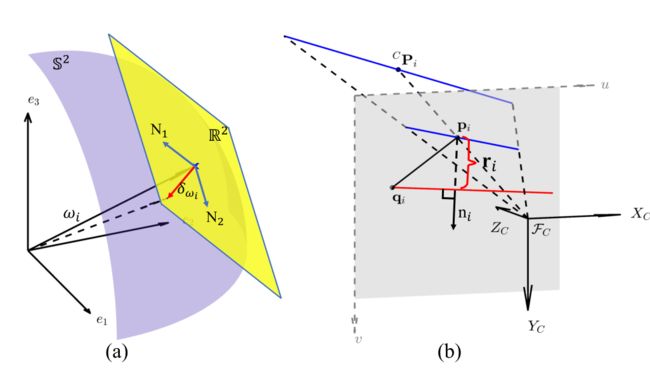
Fig. 9: (a) Perturbation to a bearing vector on S 2 \mathbb{S}^2 S2; (b) Projection of a LiDAR edge point, expressed in the camera frame C P i ^CP_i CPi, to the image plane p i p_i pi, and the computation of residual r i r_i ri.
图9:(a) S 2 \mathbb{S}^2 S2上的矢量扰动;(b) 以相机坐标系表示的激光雷达边缘点 C P i ^CP_i CPi到图像平面pi的投影,以及剩余(残差)ri的计算。
Similarly, let d i d_i di be the depth measurement and δ d i ∼ N ( 0 , ∑ d i ) δd_i∼ N(0,∑_{d_i}) δdi∼N(0,∑di) be the ranging error, then the ground-truth depth d i g t d^{gt}_i digti is
同样,设 d i d_i di为深度测量值, δ d i ∼ N ( 0 , ∑ d i ) δd_i∼ N(0,∑_{d_i}) δdi∼N(0,∑di)为测距误差,则深度真值 d i g t d^{gt}_i digt为

Combining (5) and (6), we obtain the relation between the ground-truth point location LPgti and its measurement LPi:
结合(5)和(6),我们得到了点位置 L P i g t ^LP^{gt}_i LPigt真值与其测量 L P i ^LP_i LPi之间的关系:
L P i ^LP_i LPi为激光采样点, L w i ^Lw_i Lwi为该激光点的测量噪声,最后这一块怎么来的(小量的平方忽略,e去哪了,-号怎么来的?看看罗德里格斯)
L w i ^Lw_i Lwi = 参数 * [测距误差, 方向误差] T ^T T
L ∑ i ^L∑_i L∑i 激光测量的协方差 ,距离协方差为1×1,方向协方差为2×2,所以激光的测量协方差为3×3
假设a符合高斯分布,其方差为A 对a乘以系数k, 则 k a ka ka的方差为 k 2 A k^2A k2A
若a为向量,则其协方差为A的矩阵
若F矩阵乘以a向量,其协方差为 F A F T FAF^T FAFT
若向量a的协方差矩阵为A,向量b的协方差矩阵为B,则向量a+向量b的协方差矩阵为A+B矩阵
This noise model will be used to produce a consistent extrinsic calibration as detailed follow
该噪声模型将用于产生一致的外参校准,详情如下:
2) Calibration Formulation and Optimization:
Let LPi be an edge point extracted from the LiDAR point cloud and its corresponding edge in the image is represented by its normal vector ni∈ S1and a point qi∈ R2 lying on the edge (Section III-B.2). Compensating the noise in LPi and projecting it to the image plane using the ground-truth extrinsic should lie exactly on the edge (ni,qi) extracted from the image (see (1 – 3) and Fig. 9 (b)):
2) 标定公式和优化:定义 L P i ^LP_i LPi为从激光雷达点云中提取的边缘点,其在图像中的对应边缘由其法向量ni∈ S 1 \mathbb{S}^{1} S1和位于边缘上一个点 q i ∈ R 2 q_i∈\mathbb{R}^{2} qi∈R2 表示(第III-B.2节)。补偿 L P i ^LP_i LPi中的噪声并使用真值外参将其投影到图像平面上,应正好位于从图像中提取的边缘(ni,qi)(参见(1-3)和图9(b)):

where L w i ∈ N ( 0 , L Σ i ) { }^{L} \mathbf{w}_{i} \in \mathcal{N}\left(\mathbf{0},{ }^{L} \boldsymbol{\Sigma}_{i}\right) Lwi∈N(0,LΣi) and I w i ∈ N ( 0 , I Σ i ) { }^{I} \mathbf{w}_{i} \in \mathcal{N}\left(\mathbf{0},{ }^{I} \boldsymbol{\Sigma}_{i}\right) Iwi∈N(0,IΣi) are detailed in the previous section.
[(激光点+测量噪声)转到相机坐标系再投影到像素坐标系再产生畸变 - (相机点+相机的测量噪声)] * 法向量 = 0(点到直线距离 =0)

Fig. 9: (a) Perturbation to a bearing vector on $\mathbb{S}^2; (b) Projection of a LiDAR edge point, expressed in the camera frame C P i ^CP_i CPi, to the image plane p i p_i pi, and the computation of residual r i r_i ri.
图9:(a) S 2 \mathbb{S}^2 S2上方的矢量扰动;(b) 以相机坐标系表示的激光雷达边缘点 C P i ^CP_i CPi到图像平面pi的投影,以及剩余(残差)ri的计算。
Equation (9) implies that one LiDAR edge point imposes one constraint to the extrinsic, which is in agreement with Section III-A that an edge feature imposes two constraints to the extrinsic as an edge consists of two independent points. Moreover, (9) imposes a nonlinear equation for the extrinsic L C T ^C_LT LCT in terms of the measurements LPi,ni,qi and unknown noise Lwi,Iwi. This nonlinear equation can be solved in an iterative way: let L C T ‾ ^C_L\overline{T} LCT be the current extrinsic estimate and parameterize L C T ^C_LT LCT in the tangent space of L C T ‾ ^C_L\overline{T} LCT using the 田-operation encapsulated in SE(3) [20, 21]:
等式(9)表示一个激光雷达边缘点对外参施加一个约束,这与第III-A节一致,即边缘特征对外参施加两个约束,因为边缘由两个独立点组成。此外,(9)根据测量的 L P i , n i , q i ^LP_i,n_i,q_i LPi,ni,qi和未知噪声 L w i , I w i ^Lw_i,^Iw_i Lwi,Iwi,为外参 L C T ^C_LT LCT施加了一个非线性方程。这个非线性方程可以用迭代的方式求解:让 L C T ‾ ^C_L\overline{T} LCT是当前的外参估计,并使用封装在 S E ( 3 ) SE(3) SE(3)[20,21]中的 田-operation 在 L C T ‾ ^C_L\overline{T} LCT的切线空间中参数化 L C T ^C_LT LCT:
E x p ( δ T ) Exp(\delta{T}) Exp(δT)就是李群, δ T \delta{T} δT就是 S E ( 3 ) SE(3) SE(3)的李代数
Substituting (10) into (9) and approximating the resultant equation with first order terms lead to
将(10)代入(9)并用一阶项近似结果方程,得到

where
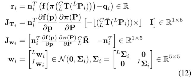
r i r_i ri表示残差, J T i J_{T_i} JTi 表示残差对外参求导(类比十四讲p187,其中 ∂ f ( p ′ ) ∂ ξ \frac{\partial \mathbf{f}(\mathbf{p'})}{\partial \mathbf{ξ}} ∂ξ∂f(p′) = [I,-p '×]), J w i J_{w_i} Jwi表示残差对噪声求导 , w i w_i wi 表示噪声,两个雅可比为什么是1×6和1×5:点到直线距离是1维的,外参是6维的,所以是1×6;激光误差是3维的,图像误差是2维的,所以是1×2,合起来就是1×5; wi的协方差由图像测量协方差2×2和激光测量协方差组成,所以为5×5。噪声雅可比是怎么求出来的?
The calculation of riis illustrated in Fig. 9 (b). Equation (11) defines the constraint from one edge correspondence, stacking all N such edge correspondences leads to
r i r_i ri的计算如图9(b)所示。等式(11)定义了来自一条边对应的约束,将所有N条这样的边对应叠加在一起将导致

目的是求 δ T \delta T δT
为什么残差不是r是v:r是初始残差,v是更新后的残差。残差的本质就是不可观的 = − j w W =-j_wW =−jwW

Based on (14), we propose our maximal likelihood (and meanwhile the minimum variance) extrinsic estimation:
基于(14),我们提出了我们的最大似然(同时最小方差)外参估计:
对于高斯分布 x ∼ N ( μ , σ ) x\sim \mathcal{N}(\mu,\sigma) x∼N(μ,σ),其概率密度函数展开形式
对应论文 v ∼ N ( 0 , J w ∑ J w T ) v\sim \mathcal{N}\left(\mathbf{0}, \mathbf{J}_{\mathbf{w}} \sum\mathbf{J}_{\mathbf{w}}^T\right) v∼N(0,Jw∑JwT),对应十四讲为p123
最大似然 = 求ln(f(x))最大 = 求最小化 ( x − μ ) T ∑ − 1 ( x − μ ) (x-\mu)^T\sum^{-1}(x-\mu) (x−μ)T∑−1(x−μ)
此处 x − μ = v = r + J T δ T x-\mu = v = r+J_T\delta T x−μ=v=r+JTδT,
优化方向,类比十四讲p126 ( y − H x = e N ( 0 , ∑ ) , x ∗ = a r g m i n ( e T ∑ − 1 e ) (y-Hx = e~ \mathcal{N}(\mathbf{0},\sum), x* = argmin(e^T\sum^{-1}e) (y−Hx=e N(0,∑),x∗=argmin(eT∑−1e).该问题有唯一解 ( H T ∑ − 1 H ) − 1 H T ∑ − 1 y (H^T\sum^{-1}H)^{-1}H^T\sum^{-1}y (HT∑−1H)−1HT∑−1y
对应论文 r − ( − J ) δ T = v ∼ N ( 0 , J w ∑ J w T ) r-(-J)\delta T = v\sim \mathcal{N}\left(\mathbf{0}, \mathbf{J}_{\mathbf{w}} \sum\mathbf{J}_{\mathbf{w}}^T\right) r−(−J)δT=v∼N(0,Jw∑JwT)


The above process ( 16 and ( 17 ) ) (17)) (17)) iterates until convergence (i.e., ∥ δ T ∗ ∥ < ε \left\|\delta \mathbf{T}^{*}\right\|<\varepsilon ∥δT∗∥<ε ) and the converged L C T ‾ { }_{L}^{C} \overline{\mathbf{T}} LCT is the calibrated extrinsic.
上述过程((16)和(17))迭代直至收敛(即 ∥ δ T ∗ ∥ < ε \left\|\delta \mathbf{T}^{*}\right\|<\varepsilon ∥δT∗∥<ε),收敛的 L C T ‾ { }_{L}^{C} \overline{\mathbf{T}} LCT即为校准的外参。
3) Calibration Uncertainty:
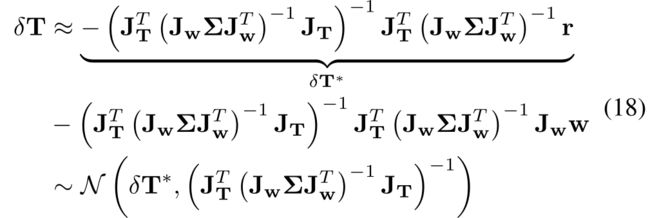
Besides the extrinsic calibration, it is also useful to estimate the calibration uncertainty, which can be characterized by the covariance of the error between the ground-truth extrinsic and the calibrated one. To do so, we multiply both sides of 13 by J T T ( J w Σ J w T ) − 1 \mathbf{J}_{\mathbf{T}}^{T}\left(\mathbf{J}_{\mathbf{w}} \boldsymbol{\Sigma} \mathbf{J}_{\mathbf{w}}^{T}\right)^{-1} JTT(JwΣJwT)−1 and solve for δ T \delta \mathbf{T} δT :
3) 校准不确定度:除了外参校准外,还可以估算校准的不确定度,其特征是外参真值和计算出的外参之间的误差的协方差。为此,我们将(13)的两边乘以 J T T ( J w Σ J w T ) − 1 \mathbf{J}_{\mathbf{T}}^{T}\left(\mathbf{J}_{\mathbf{w}} \boldsymbol{\Sigma} \mathbf{J}_{\mathbf{w}}^{T}\right)^{-1} JTT(JwΣJwT)−1 ,然后求解 δ T \delta \mathbf{T} δT:
同式子16的推导过程, ( y − H x = e N ( 0 , ∑ ) , x ∗ = a r g m i n ( e T ∑ − 1 e ) (y-Hx = e~ \mathcal{N}(\mathbf{0},\sum), x* = argmin(e^T\sum^{-1}e) (y−Hx=e N(0,∑),x∗=argmin(eT∑−1e).该问题有唯一解 ( H T ∑ − 1 H ) − 1 H T ∑ − 1 y (H^T\sum^{-1}H)^{-1}H^T\sum^{-1}y (HT∑−1H)−1HT∑−1y
此处为 r − ( − J ) δ T = v ∼ N ( 0 , J w ∑ J w T ) r-(-J)\delta T = v\sim \mathcal{N}\left(\mathbf{0}, \mathbf{J}_{\mathbf{w}} \sum\mathbf{J}_{\mathbf{w}}^T\right) r−(−J)δT=v∼N(0,Jw∑JwT)
和 J w W − ( − J ) δ T ∼ N ( 0 , J w ∑ J w T ) J_wW - (-J)\delta T\sim \mathcal{N}\left(\mathbf{0}, \mathbf{J}_{\mathbf{w}} \sum\mathbf{J}_{\mathbf{w}}^T\right) JwW−(−J)δT∼N(0,Jw∑JwT)
协方差是海赛矩阵的倒数
which means that the ground truth δ T δT δT, the error between the ground truth extrinsic L C T ^C_LT LCT and the estimated one L C T ‾ ^C_L\overline{T} LCTand parameterized in the tangent space of L C T ‾ ^C_L\overline{T} LCT, is subject to a Gaussian distribution that has a mean δ T ∗ δT^∗ δT∗and covariance equal to the inverse of the Hessian matrix of (15). At convergence, the δ T ∗ δT^∗ δT∗ is near to zero, and the covariance is
这意味着,(误差)真值 δ T δT δT,即外参真值 L C T ^C_LT LCT和估计值 L C T ‾ ^C_L\overline{T} LCT之间的误差,在 L C T ‾ ^C_L\overline{T} LCT的切线空间中参数化,服从均值为 δ T ∗ δT^∗ δT∗,协方差等于(15)的Hessian矩阵的倒数的高斯分布。在收敛时, δ T ∗ δT^∗ δT∗ 接近于零,协方差为

We use this covariance matrix to characterize our extrinsic calibration uncertainty.
我们使用此协方差矩阵来表征外参校准不确定度。
D. Analysis of Edge Distribution on Calibration Result
标定结果的边缘分布分析
The Jacobian JTi in (12) denotes the sensitivity of residual with respect to the extrinsic variation. In case of very few or poorly distributed edge features, JTi could be very small, leading to large estimation uncertainty (covariance) as shown by (19). In this sense, the data quality is automatically and quantitatively encoded by the covariance matrix in (19). In practice, it is usually useful to have a quick and rough assessment of the calibration scene before the data collection. This can be achieved by analytically deriving the Jacobian JTi. Ignoring the distortion model and substituting the pinhole projection model π(·) to (12), we obtain
(12)中的雅可比 J T i J_{T_i} JTi表示残差对外参变化的敏感性。在边缘特征很少或分布不均匀的情况下, J T i J_{T_i} JTi可能非常小,导致较大的估计不确定性(协方差),如(19)所示( J T i J_{T_i} JTi越小, ∑ T \sum T ∑T越大)。在这个意义上,数据质量由(19)中的协方差矩阵自动和定量地编码(encoded)。在实践中,在数据收集之前对校准场景进行快速和粗略的评估通常是有用的。这可以通过解析推导雅可比 J T i J_{T_i} JTi来实现。忽略畸变模型,将针孔投影模型π(·)代入(12),我们得到
对应14讲p187,经典的针孔相机模型重投影误差对位姿求导

where C P i = [ X i Y i Z i ] T ^CP_i=[X_i Y_i Z_i]^T CPi=[XiYiZi]T is the LiDAR edge point L P i ^LP_i LPirepresented in the camera frame (see (1)). It is seen that points near to the center of the image after projection (i.e., small Xi/Zi, Yi/Zi) lead to small Jacobian. Therefore it is beneficial to have edge features equally distributed in the image. Moreover, since LiDAR noises increase with distance as in (8), the calibration scene should have moderate depth.
其中 C P i = [ X i Y i Z i ] T ^CP_i=[X_i Y_i Z_i]^T CPi=[XiYiZi]T是激光雷达边缘点 L P i ^LP_i LPi(参见(1))转到相机坐标系下的坐标。可以看出,投影后靠近图像中心的小点(即Xi/Zi、Yi/Zi)会导致小雅可比矩阵。因此,使边缘特征在图像中均匀分布是有益的。此外,由于激光雷达噪声随着距离的增加而增加,如(8)所示,校准场景应具有中等深度。
E. Initialization and Rough Calibration
The presented optimization-based extrinsic calibration method aims for high-accuracy calibration but requires a good initial estimate of the extrinsic parameters that may not always be available. To widen its convergence basin, we further integrate an initialization phase into our calibration pipeline where the extrinsic value is roughly calibrated by maximizing the percent of edge correspondence (P.C.) defined below:
提出的基于优化的外参校准方法旨在实现高精度校准,但需要对外参进行良好的初始估计,这些参数可能并不总是可用的。为了扩大其收敛范围,我们进一步将初始化阶段整合到校准pipeline中,其中通过最大化以下定义的边缘对应百分比(the percent of edge correspondence P.C.)粗略校准外参:

where Nsum is the total number of LiDAR edge points and Nmatch is the number of matched LiDAR edge points. The matching is based on the distance and direction of a LiDAR edge point (after projected to the image plane) to its nearest edge in the image (see Section III-B.2). The rough calibration is performed by an alternative grid search on rotation (grid size 0.5◦) and translation (grid size 2cm) over a given range.
其中 N s u m N_{sum} Nsum是激光雷达边缘点的总数, N m a t c h N_{match} Nmatch是匹配的激光雷达边缘点的数量。匹配基于激光雷达边缘点(投影到图像平面后)到图像中最近边缘的距离和方向(见第III-B.2节)。通过在给定范围内旋转 (grid size 0.5◦)和平移(grid size 2cm)的替代网格搜索执行粗标定
4.EXPERIMENTS AND RESULTS
In this section, we validate our proposed methods in a variety of real-world experiments. We use a solid-state LiDAR called Livox A VIA, which achieves high-resolution pointcloud measurements at stationary due to its non-repetitive scanning [8], and an Intel Realsense-D435i camera (see Fig. 10). The camera intrinsic, including distortion models, has been calibrated beforehand. During data acquisition, we fix the LiDAR and camera in a stable position and collect point cloud and image simultaneously. The data acquisition time is 20 seconds for the Avia LiDAR to accumulate sufficient points.
在本节中,我们将在各种实际实验中验证我们提出的方法。我们使用名为Livox a VIA的固态激光雷达,由于其非重复扫描[8],可在静止状态下实现高分辨率点云测量,并使用Intel Realsense-D435i相机(见图10)。摄像机的内参,包括畸变模型,已经预先校准过。在数据采集过程中,我们将激光雷达和摄像机固定在稳定的位置,同时采集点云和图像。数据采集时间为20秒,以便Avia激光雷达积累足够的点数。
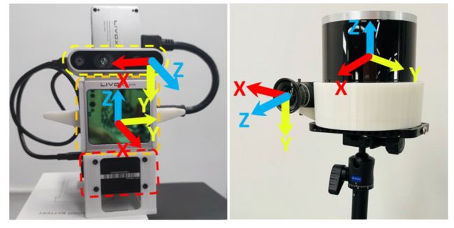
Fig. 10: Our sensor suite. Left is Livox Avia1LiDAR and Intel Realsense-D435i2camera, which is used for the majority of the experiments (Section IV .A and B). Right is spinning LiDAR (OS2643)and industry camera (MV-CA013-21UC4), which is used for verification on fixed resolution LiDAR (Section IV.C) . Each sensor suite has a nominal extrinsic, e.g., for Livox A VIA, it is (0,−π 2,π 2). for rotation (ZYX Euler Angle) and zeros for translation.
图10:我们的传感器套件。左边是Livox Avia1激光雷达和Intel Realsense-D435i2照相机,用于大多数实验(第四节A和B)。右侧为旋转激光雷达(OS2643)和工业摄像机(MV-CA013-21UC4),用于验证固定分辨率激光雷达(第IV.C节)。每个传感器套件都有一个标称外参,例如,对于Livox a VIA,它是 ( 0 , − π / 2 , π / 2 ) (0,−π/2,π/2) (0,−π/2,π/2)校正用于旋转(ZYX Euler角),用0校正平移。
A. Calibration Results in Outdoor and Indoor Scenes
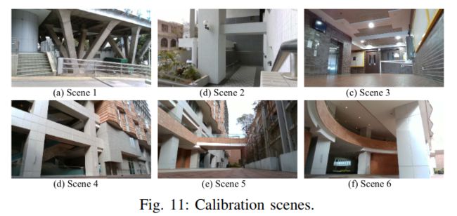
We test our methods in a variety of indoor and outdoor scenes shown in Fig. 11, and validate the calibration performance as follows.
我们在图11所示的各种室内和室外场景中测试我们的方法,并验证校准性能如下。
1) Robustness and Convergence Validation:
To verify the robustness of the full pipeline, we test it on each of the 6 scenes individually and also on all scenes together. For each scene-setting, 20 test runs are conducted, each with a random initial value uniformly drawn from a neighborhood (±5◦for rotation and ±10cm for translation) of the value obtained from the CAD model. Fig. 12 shows the percent of edge correspondence before and after the rough calibration and the convergence of the normalized optimization cost 1 N match r T ( J w Σ J w ) − 1 \frac{1}{N_{\text {match }}} \mathbf{r}^{T}\left(\mathbf{J}_{\mathbf{w}} \mathbf{\Sigma} \mathbf{J}_{\mathbf{w}}\right)^{-1} Nmatch 1rT(JwΣJw)−1 during the fine calibration. It is seen that, in all 7 scene settings and 20 test runs of each, the pipeline converges for both rough and fine calibration.
1) 稳健性和收敛性验证:为了验证整个pipeline的稳健性,我们分别在6个场景中的每一个场景上以及在所有场景中一起对其进行了测试。对于每个场景设置,执行20次测试运行,每个测试运行具有从CAD模型获得的值(以这个作为真值?)的邻域(±5◦for rotation and ±10cm for translation)中均匀绘制的随机初始值。图12显示了粗标定前后边缘对应的百分比以及精细校准期间归一化优化成本 1 N match r T ( J w Σ J w ) − 1 r \frac{1}{N_{\text {match }}} \mathbf{r}^{T}\left(\mathbf{J}_{\mathbf{w}} \mathbf{\Sigma} \mathbf{J}_{\mathbf{w}}\right)^{-1} \mathbf{r} Nmatch 1rT(JwΣJw)−1r的收敛度。可以看出,在所有7个场景设置和每个场景的20个测试运行中,pipeline在粗校准和精校准中都能收敛。
优化成本怎么来的: r T ∗ r^T * rT∗ 权重 ∗ r * r ∗r
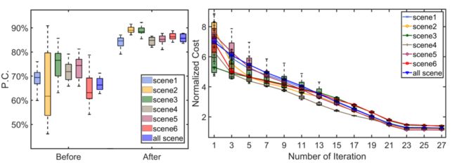
Fig. 12: Percent of edge correspondence before and after the rough calibration (left) and cost during the optimization (right).
图12:粗校准前后边缘对应的百分比(左)和优化期间的cost(右)。
Fig. 13 shows the distribution of converged extrinsic values for all scene settings. It is seen that in each case, the extrinsic value converges to almost the same value regardless of the large range of initial value distribution. A visual example illustrating the difference before and after our calibration pipeline is shown in Fig. 14. Our entire pipeline, including feature extraction, matching, rough calibration and fine calibration, takes less than 60 seconds
图13显示了所有场景设置的收敛外参的分布。可以看出,在每种情况下,无论初始值分布的范围如何,外参都收敛到几乎相同的值。图14显示了一个直观的例子,说明了我们校准pipeline前后的差异。我们的整个pipeline,包括特征提取,匹配,粗略校准和精细校准,只需不到60秒
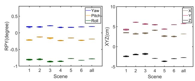
Fig. 13: Distribution of converged extrinsic values for all scene settings. The displayed extrinsic has its nominal part removed.
图13:所有场景收敛外参的分布。显示的外参已删除其标称部分。

Fig. 14: LiDAR projection image overlaid on the camera image with an initial (left) and calibrated extrinsic (right). The LiDAR projection image is colored by Jet mapping on the measured point intensity.
图14:激光雷达投影图像叠加在相机图像上,使用初始外参(左)和校准后的外参(右)的结果。激光雷达投影图像通过测量点强度使用Jet mapping进行着色。
2) Consistency Evaluation:
To evaluate the consistency of the extrinsic calibration in different scenes, we compute the standard deviation of each degree of freedom of the extrinsic:
2) 一致性评估:为了评估外参校准在不同场景中的一致性,我们计算外参校准的每个自由度的标准偏差:

where ΣT is computed from (19). As shown in Fig. 13, the converged extrinsic in a scene is almost identical regardless of its initial value, we can therefore use this common extrinsic to evaluate the standard deviation of the extrinsic calibrated in each scene. The results are summarized in Fig. 15. It is seen that the 3σ of all scenes share overlaps and as expected, the calibration result based on all scenes have much smaller uncertainty and the corresponding extrinsic lies in the 3σ confidence level of the other 6 scenes. These results suggest that our estimated extrinsic and covariance are consistent.
式中,∑T 由(19)计算得出。如图13所示,无论初始值如何,场景中收敛的外参变量几乎相同,因此我们可以使用此相同的外参变量来评估每个场景中校准的外参的标准偏差。结果总结如图15所示。可以看出,所有场景的3个σ(标准偏差)是存在重叠部分(share overlaps)的,并且正如预期的那样,基于所有场景的标定结果具有更小的不确定性,且对应的外参在其他6个场景3个σ的置信水平中。这些结果表明,我们估计的外参和协方差是一致的。
 Fig. 15: Calibrated extrinsic with 3σ bound in all 7 scene settings. The displayed extrinsic has its nominal part removed.
图15:在所有7个场景设置中使用3σ边界校准的外参。显示的外参已删除其标称部分。
3) Cross Validation:
We evaluate the accuracy of our calibration via cross validation among the six individual scenes. To be more specific, we calibrate the extrinsic in one scene and apply the calibrated extrinsic to the calibration scene and all the rest five scenes. We obtain the residual vector r whose statistical information (e.g., mean, median) reveal the accuracy quantitatively. The results are summarized in Fig. 16, where the 20% largest residuals are considered as outliers and removed from the figure. It is seen that in all calibration and validation scenes (36 cases in total), around 50% of residuals, including the mean and median, are within one pixel. This validates the robustness and accuracy of our methods.
3) 交叉验证:我们通过六个单独场景之间的交叉验证来评估校准的准确性。更具体地说,我们在一个场景中校准外参,并将校准的外参应用于校准场景和所有其他五个场景。我们得到了残差向量r,其统计信息(如平均值、中值)定量地揭示了精度。图16总结了结果,其中20%的最大残差被视为异常值,并从图中删除。可以看出,在所有校准和验证场景(总共36个案例)中,约50%的残差(包括平均值和中值)在一个像素内。这验证了我们方法的稳健性和准确性。
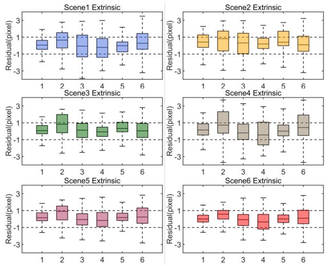
Fig. 16: Cross validation results. The 6 box plots in i-th subfigure summarizes the statistical information (from up to down: maximum, third quartile, median, first quartile, and minimum) of residuals of the six scenes applied with extrinsic calibrated from scene i.
图16:交叉验证结果。第i个子图中的6个方框图总结了六个场景的残差统计信息(从上到下:最大值、第三个四分位数、中值、第一个四分位数和最小值),这些残差应用了场景i中的外参。
4) Bad Scenes:
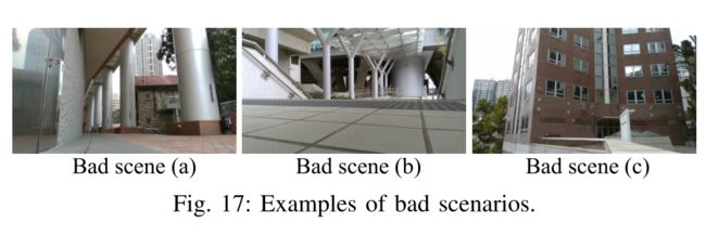
As analyzed in Section III-D, our method requires a sufficient number of edge features distributed properly. This does put certain requirements to the calibration scene. We summarize the scenarios in which our algorithm does not work well in Fig.17. The first is when the scene contains all cylindrical objects. Because the edge extraction is based on plane fitting, round objects will lead to inaccurate edge extraction. Besides, cylindrical objects will also cause parallax issues, which will reduce calibration accuracy. The second is the uneven distribution of edges in the scene. For example, most of the edges are distributed in the upper part of the image, which forms poor constraints that are easily affected by measurement noises. The third is when the scene contains edges only along one direction (e.g., vertical), in which the constraints are not sufficient to uniquely determine the extrinsic parameters.
4) 坏场景:如第III-D节所分析的,我们的方法需要合理分布的足够数量的边缘特征。这确实对校准场景提出了某些要求。我们在图17中总结了我们的算法不能很好工作的场景。第一种情况是,场景包含所有圆柱形对象。由于边缘提取是基于平面拟合的,因此圆形对象会导致边缘提取不准确。此外,圆柱形物体也会导致视差问题,从而降低校准精度。第二个是场景中边缘的不均匀分布。例如,大多数边缘分布在图像的上部,这形成了很差的约束,很容易受到测量噪声的影响。第三种情况是,场景中的边仅沿一个方向(例如,垂直方向),其中约束不足以唯一确定外部参数。
B. Comparison Experiments
We compare our methods with [4, 6], which both use checkerboard as a calibration target. The first one ACSC [4] uses point reflectivity measured by the LiDAR to estimate the 3D position of each grid corner on the checkerboard and computes the extrinsic by solving a 3D-2D PnP problem. Authors of [4] open sourced their codes and data collected on a Livox LiDAR similar to ours, so we apply our method to their data. Since each of their point cloud data only has 4 seconds data, it compromises the accuracy of the edge extraction in our method. To compensate for this, we use three (versus 12 used for ACSC [4]) sets of point clouds in the calibration to increase the number of edge features. We compute the residuals in (12) using the two calibrated extrinsic, the quantitative result is shown in Fig. 18 (a).
我们将我们的方法与[4,6]进行比较,它们都使用棋盘作为校准目标。第一个ACSC[4]使用激光雷达测量的点反射率来估计棋盘格上每个网格角的3D位置,并通过解决3D-2D PnP问题来计算外参。[4]的作者公开了他们在Livox激光雷达上收集的代码和数据,与我们的类似,因此我们将我们的方法应用于他们的数据。由于他们的每个点云数据只有4秒的数据,因此在我们的方法中会影响边缘提取的准确性。为了补偿这一点,我们在校准中使用了三组(ACSC[4]使用了12组)点云,以增加边缘特征的数量。我们使用两个校准的外参计算(12)中的残差,定量结果如图18(a)所示。
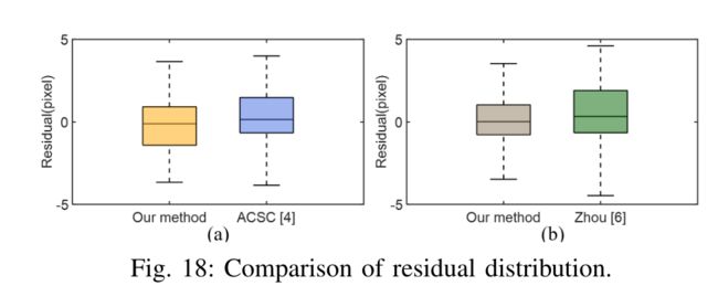
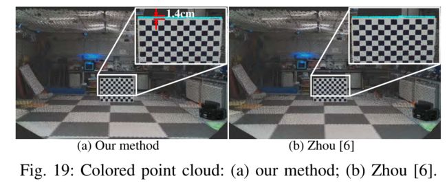
The second method [6] estimates the checkerboard pose from the image by utilizing the known checkerboard pattern size. Then, the extrinsic is calibrated by minimizing the distance from LiDAR points (measured on the checkerboard) to the checkerboard plane estimated from the image. The method is designed for multi-line spinning LiDARs that have much lower resolution than ours, so we adopt this method to our LiDAR and test its effectiveness. The method in [6] also considers depth-discontinuous edge points, which are less accurate and unreliable on our LiDAR. So to make a fair comparison, we only use the plane points in the calibration when using [6]. To compensate for the reduced number of constraints, we place the checkerboard at more than 36 different locations and poses. In contrast, our method uses only one pair of data. Fig. 19 shows the comparison results on one of the calibration scenes with the quantitative result supplied in Fig. 18 (b). It can be seen that our method achieves similar calibration accuracy with [6] although using no checkerboard information (e.g., pattern size). We also notice certain board inflation (the blue points in the zoomed image of Fig. 19), which is caused by laser beam divergence explained in Section III-B. The inflated points are 1.4cm wide and at a distance of 6m, leading to an angle of 0.014/6 = 0.13◦, which agrees well with half of the vertical beam divergence angle (0.28°).
第二种方法[6]利用已知的棋盘格图案大小,从图像中估计棋盘格姿势。然后,通过最小化激光雷达点(在棋盘上测量)到图像估计的棋盘平面的距离来校准外参。该方法适用于分辨率比我们低得多的多线旋转激光雷达,因此我们将该方法应用于我们的激光雷达并测试其有效性。[6]中的方法还考虑了深度不连续的边缘点,这些点在我们的激光雷达上精度较低且不可靠。因此,为了进行公平比较,在使用[6]时,我们仅在校准中使用平面点。为了补偿减少的约束数量,我们将棋盘放置在36个不同的位置和姿势上。作为对比,我们的方法只使用一对数据。图19展示了其中一个校准场景上的比较结果与图18(b)中提供的定量结果。可以看出,我们的方法实现了与[6]相似的校准精度,尽管没有使用棋盘格信息(例如,图案大小)。我们还注意到某些标定板膨胀(图19放大图像中的蓝色点),这是由第III-B节中解释的激光束发散引起的。膨胀点宽1.4cm,距离6m,导致角度为0.014/6=0.13◦, 这与垂直光束发散角的一半(0.28°)非常吻合。
C. Applicability to Other Types of LiDARs
Besides Livox Avia, our method could also be applied to conventional multi-line spinning LiDARs, which possess lower resolution at stationary due to the repetitive scanning. To boost the scan resolution, the LiDAR could be moved slightly (e.g., a small pitching movement) so that the gaps between scanning lines can be filled. A LiDAR (-inertial) odometry [22] could be used to track the LiDAR motion and register all points to its initial pose, leading to a much higher resolution scan enabling the use of our method. To verify this, We test our methods on another sensor platform (see Fig. 10) consisting of a spinning LiDAR (Ouster LiDAR OS2-64) and an industrial camera (MV-CA013-21UC). The point cloud registration result and detailed quantitative calibration results are presented in the supplementary material (https://github.com/ChongjianYUAN/SupplementaryMaterials) due to the space limit. The results show that our method is able to converge to the same extrinsic for 20 initial values that are randomly sampled in the neighborhood (±3◦in rotation and ±5cm) of the value obtained from the CAD model.
除了Livox Avia外,我们的方法还可以应用于传统的多线旋转激光雷达,由于重复扫描,这些激光雷达在静止时的分辨率较低。为了提高扫描分辨率,可以稍微移动激光雷达(例如,一个小的俯仰运动),以便填充扫描线之间的间隙。激光雷达(惯性)里程计[22]可用于跟踪激光雷达运动并将所有点register到其初始姿态,从而实现更高分辨率的扫描,从而使用我们的方法。为了验证这一点,我们在另一个传感器平台(见图10)上测试了我们的方法,该平台由旋转激光雷达(驱逐激光雷达OS2-64)和工业摄像机(MV-CA013-21UC)组成。补充资料中给出了点云配准结果和详细的定量校准结果(https://github.com/ChongjianYUAN/SupplementaryMaterials)。结果表明,对于从CAD模型获得的值的邻域(±3◦in rotation and ±5cm)中随机抽样的20个初始值,我们的方法能够收敛到相同的外参。
5.Conclusion
This paper proposed a novel extrinsic calibration method for high resolution LiDAR and camera in targetless environments. We analyzed the reliability of different types of edges and edge extraction methods from the underlying LiDAR measuring principle. Based on this, we proposed an algorithm that can extract accurate and reliable LiDAR edges based on voxel cutting and plane fitting. Moreover, we theoretically analyzed the edge constraint and the effect of edge distribution on extrinsic calibration. Then a high-accuracy, consistent, automatic, and targetless calibration method is developed by incorporating accurate LiDAR noise models. Various outdoor and indoor experiments show that our algorithm can achieve pixel-level accuracy comparable to target-based methods. It also exhibits high robustness and consistency in a variety of natural scenes.
针对无目标(target-less)环境下的高分辨率激光雷达和相机,提出了一种新的外参标定方法。我们从基本的激光雷达测量原理出发,分析了不同类型边缘和边缘提取方法的可靠性。在此基础上,提出了一种基于体素切割和平面拟合的激光雷达边缘提取算法。此外,我们还从理论上分析了边缘约束和边缘分布对外部校准的影响。然后结合精确的激光雷达噪声模型,提出了一种高精度、一致性、自动、无目标的标定方法。各种室外和室内实验表明,我们的算法可以达到与基于目标的方法相当的像素级精度。它在各种自然场景中也表现出高度的鲁棒性和一致性。


