Verilog零基础入门(边看边练与测试仿真)-状态机-笔记(7-10讲)
文章目录
- 第七讲
- 第八讲
- 第九讲
- 第十讲
第七讲
1、两种状态的代码:
//最简单的状态机,三角波发生器;
`timescale 1ns/10ps
module tri_gen(
									clk,
									res,
									d_out
									);
input             clk;
input             res;
output[8:0]       d_out;

reg               state;//主状态机寄存器
reg[8:0]          d_out;

always@(posedge clk or negedge res )
if(~res)begin
	state<=0;d_out<=0;
end
else begin
	case(state)
	0://上升;
	begin
		d_out<=d_out+1;
		if(d_out==299)begin
			state<=1;
		end
	end
	1://下降
	begin
		d_out<=d_out-1;
		if(d_out==1)begin
			state<=0;
		end
	end
  endcase
end

endmodule

//---------testbench of tri_gen-----
module tri_gen_tb;
reg               clk,res;
wire[8:0]         d_out;
tri_gen U1(
									.clk(clk),
									.res(res),
									.d_out(d_out)
									);

initial begin
	                 clk<=0;res<=0;
	           #17   res<=1;
	           #8000 $stop;
end

always #5 clk<=~clk;
endmodule
//2023-0913,time
//最简单的状态机,三角波发生器;
`timescale 1ns/10ps
module tri_gen(
									clk,
									res,
									d_out
									);
input             clk;
input             res;
output[8:0]       d_out;

reg[1:0]          state;//主状态机寄存器
reg[8:0]          d_out;

reg[7:0]          con;//计数器,记录平顶周期个数

always@(posedge clk or negedge res )
if(~res)begin
	state<=0;d_out<=0;con<=0;
end
else begin
	case(state)
	0://上升;
	begin
		d_out<=d_out+1;
		if(d_out==299)begin
			state<=1;
		end
	end
	1://平顶
	begin
		if(con==200)begin
			state<=2;
			con<=0;
		end
		else begin
		  con<=con+1;
	  end
	end
	2://下降
	begin
		d_out<=d_out-1;
		if(d_out==1)begin
			state<=3;
		end
	end
	3://平顶
	begin
		if(con==200)begin
			state<=0;
			con<=0;
		end
		else begin
		  con<=con+1;
	  end
	end
  endcase
end

endmodule

//---------testbench of tri_gen-----
module tri_gen_tb;
reg               clk,res;
wire[8:0]         d_out;
tri_gen U1(
									.clk(clk),
									.res(res),
									.d_out(d_out)
									);

initial begin
	                  clk<=0;res<=0;
	           #17    res<=1;
	           #40000 $stop;
end

always #5 clk<=~clk;
endmodule
仿真波形:

3、如果state定义的[1:0],也就是有四种状态,那么如果有没用到的状态,应该用default写完全。
第八讲
//2023-09-18,time
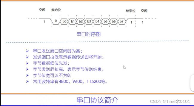
//串口数据接收
`timescale 1ns/10ps
module UART_RXer(
												 clk,
												 res,
												 RX,
												 data_out,
											 	 en_data_out
											   );
input                    clk;
input                    res;
input                    RX;
output[7:0]              data_out;//接受字节输出;
output                   en_data_out;//输出势能;

reg[7:0]                 data_out;
reg[7:0]                 state;//主状态机;
reg[12:0]                con;//用于计算比特宽度;
reg[3:0]                 con_bits;// 用于计算比特数;

reg                      RX_delay;//RX的延时;
reg                      en_data_out;
always@(posedge clk or negedge res)
if(~res)begin
	state<=0;con<=0;con_bits<=0;RX_delay<=0;en_data_out<=0;
	data_out<=0;
end
else begin
	RX_delay<=RX;
	case(state)
	0://等空闲:
	begin
		if(con==5000-1)begin
		con<=0;
		end
		else begin
		con<=con+1;
		end
		if(con==0)begin
			if(RX)begin
				con_bits<=con_bits+1;
		  end
		  else begin
		  	con_bits<=0;
		  end
		end

		if(con_bits==12)begin
			state<=1;
		end
	end

	1://等起始位
	begin
	en_data_out<=0;
		if(~RX&RX_delay)begin
			state<=2;
		end
	end
	2://收最低位b0;
	begin
		if(con==7500-1)begin
			con<=0;
			data_out[0]<=RX;
			state<=3;
		end
		else begin
			con<=con+1;
		end
	end
	3://收最低位b1;
	begin
		if(con==5000-1)begin
			con<=0;
			data_out[1]<=RX;
			state<=4;
		end
		else begin
			con<=con+1;
		end
	end
	4://收最低位b2;
	begin
		if(con==5000-1)begin
			con<=0;
			data_out[2]<=RX;
			state<=5;
		end
		else begin
			con<=con+1;
		end
	end
	5://收最低位b3;
	begin
		if(con==5000-1)begin
			con<=0;
			data_out[3]<=RX;
			state<=6;
		end
		else begin
			con<=con+1;
		end
	end
	6://收最低位b4;
	begin
		if(con==5000-1)begin
			con<=0;
			data_out[4]<=RX;
			state<=7;
		end
		else begin
			con<=con+1;
		end
	end
	7://收最低位b5;
	begin
		if(con==5000-1)begin
			con<=0;
			data_out[5]<=RX;
			state<=8;
		end
		else begin
			con<=con+1;
		end
	end
	8://收最低位b6;
	begin
		if(con==5000-1)begin
			con<=0;
			data_out[6]<=RX;
			state<=9;
		end
		else begin
			con<=con+1;
		end
	end

	9://收最低位b7;
	begin
		if(con==5000-1)begin
			con<=0;
			data_out[7]<=RX;
			state<=10;
		end
		else begin
			con<=con+1;
		end
	end
	10://产生使能信号脉冲;
	begin
		en_data_out<=1;
		state<=1;
	end
	default://
	begin
		state<=0;
		con<=0;
		con_bits<=0;
		en_data_out<=0;
	end
	endcase
end

endmodule

//-------testbench of UART_RXer-------
module UART_RXer_tb;
reg                      clk,res;
wire                     RX;
wire[7:0]                data_out;
wire                     en_data_out;

reg[25:0]                RX_send;//里面装有串口字节发送数据
assign                   RX=RX_send[0];//连接RX;

reg[12:0]                con;

UART_RXer UART_RXer(		 //同名例化;
												 clk,
												 res,
												 RX,
												 data_out,
											 	 en_data_out
											   );
initial begin
												 clk<=0;res<=0;RX_send<={1'b1,8'haa,1'b0,16'hffff};con<=0;
				#17              res<=1;
				#4000000         $stop;
end

always #5 clk<=~clk;

always@(posedge clk) begin
	if(con==5000-1)begin
		con<=0;
	end
	else begin
		con<=con+1;
	end

	if(con==0)begin
		RX_send[24:0]<=RX_send[25:1];
		RX_send[25]<=RX_send[0];
	end

end
endmodule
第九讲
//2023-09-18,time
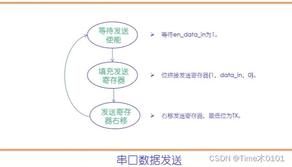
//串口发送模块
`timescale 1ns/10ps
module UART_TXer(
														clk,
														res,
														data_in,
														en_data_in,
														TX,
														rdy
														);
input                       clk;
input                       res;
input[7:0]                  data_in;//准备发送的数据
input                       en_data_in;//发送使能
output                      TX;
output                      rdy;//空闲标志,0表示空闲

reg[3:0]                    state;//主状态机寄存器;
reg[9:0]                    send_buf;//发送寄存器;
assign                      TX=send_buf[0];//连接TX;

reg[9:0]                    send_flag;//用于判断右移结束;

reg[12:0]                   con;//用于计算波特周期;
reg                         rdy;

always@(posedge clk or negedge res)
if(~res)begin
	state<=0;send_buf<=1;con<=0;send_flag<=10'b10_0000_0000;
	rdy<=0;
end
else begin
	case(state)
	0://等待使能信号
	begin
		if(en_data_in)begin
			send_buf={1'b1,data_in,1'b0};
			send_flag<=10'b10_0000_0000;
			rdy<=1;
			state<=1;
		end
	end
	1://串口发送,寄存器右移;
	begin
		if(con==5000-1)begin
			con<=0;
		end
		else begin
			con<=con+1;
		end
		if(con==5000-1)begin
			send_buf[8:0]<=send_buf[9:1];
			send_flag[8:0]<=send_flag[9:1];
		end
		if(send_flag[0])begin
			rdy<=0;
			state<=0;
		end
	end

	endcase
end
endmodule

//------testbench of UART_TXer--------
module UART_TXer_tb;
reg                        clk,res;
reg[7:0]                   data_in;
reg                        en_data_in;
wire                       TX;
wire                       rdy;
UART_TXer UART_TXer(
														clk,
														res,
														data_in,
														en_data_in,
														TX,
														rdy
														);

initial begin
                          clk<=0;res<=0;data_in<=8'h7f;en_data_in<=0;
             #17	        res<=1;
             #30          en_data_in<=1;
             #10          en_data_in<=0;

             #2000000         $stop;
end

always #5 clk=~clk;


endmodule
第十讲
//2023-09-19,time
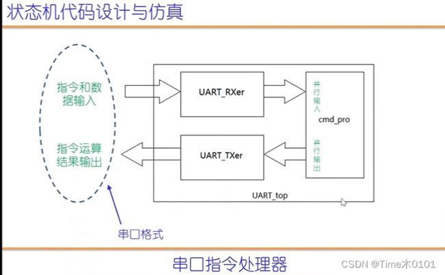
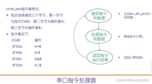
//指令处理器
module cmd_pro(
																clk,
																res,
																din_pro,
																en_din_pro,
																dout_pro,
																en_dout_pro,
																rdy
																);
input                          clk;
input                          res;
input[7:0]                     din_pro;//指令和数据输入端口;
input                          en_din_pro;//输入使能;
output[7:0]                    dout_pro;//指令执行结果;
output                         en_dout_pro;//指令输出使能;
output                         rdy;//串口发送模块空闲标志,0表示空闲;

parameter                      add_ab=8'h0a;
parameter                      sub_ab=8'h0b;
parameter                      and_ab=8'h0c;
parameter                      or_ab =8'h0d;

reg[2:0]                       state;//主状态机寄存器
reg[7:0]                       cmd_reg,A_reg,B_reg;//存放指令、A和B;
reg[7:0]                       dout_pro;
reg                            en_dout_pro;

always@(posedge clk or negedge res)begin
if(~res)begin
	state<=0;cmd_reg<=0;A_reg<=0;B_reg<=0;dout_pro<=0;
	en_dout_pro<=0;
end
else begin
	case(state)
	0://等指令;
	begin
		en_dout_pro<=0;
		if(en_din_pro)begin
			cmd_reg<=din_pro;
			state<=1;
		end
	end
	1://收A
	begin
		if(en_din_pro)begin
			A_reg<=din_pro;
			state<=2;
		end
	end
	2://收B
	begin
		if(en_din_pro)begin
			B_reg<=din_pro;
			state<=3;
		end
	end
	3://指令译码和执行;
	begin
		state<=4;//指令译码一个时钟周期就可以,所以可以没条件
		case(cmd_reg)
		add_ab: begin dout_pro<=A_reg+B_reg; end
		sub_ab: begin dout_pro<=A_reg-B_reg; end
		and_ab: begin dout_pro<=A_reg&B_reg; end
		or_ab:  begin dout_pro<=A_reg|B_reg; end
		endcase
	end
	4://发送指令执行结果;
	begin
		if(~rdy)begin
			en_dout_pro<=1;
			state<=0;

		end
	end
	default://
	begin
		state<=0;
		en_dout_pro<=0;
	end
  endcase
end
endmodule
//2023-09-19,time
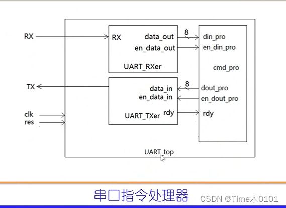
//串口指令处理器;
`timescale 1ns/10ps
module UART_top(
											clk,
											res,
											RX,
											TX
											);
input                 clk;
input                 res;
input                 RX;
output                TX;

wire[7:0]             	 din_pro;
wire                  	 en_din_pro;
wire[7:0]             	 dout_pro;
wire                   	 en_dout_pro;
wire                     rdy;

UART_RXer UART_RXer(
												 .clk(clk),
												 .res(res),
												 .RX(RX),
												 .data_out(din_pro),
											 	 .en_data_out(en_din_pro)
											   );

UART_TXer UART_TXer(
												 .clk(clk),
												 .res(res),
												 .data_in(dout_pro),
												 .en_data_in(en_data_),
												 .TX(TX),
												 .rdy(rdy)
													);

cmd_pro cmd_pro(
													.clk(clk),
													.res(res),
													.din_pro(din_pro),
													.en_din_pro(en_din_pro),
													.dout_pro(dout_pro),
													.en_dout_pro(en_dout_pro),
													.rdy(rdy)
													);
endmodule

//-------testbench of UART_top------
module UART_top_tb;
reg                       clk,res;
wire                      RX;
wire                      TX;


reg[45:0]                RX_send;//里面装有串口字节发送数据
assign                   RX=RX_send[0];//连接RX;

reg[12:0]                con;

UART_top UART_top(
													clk,
													res,
													RX,
													TX
													);

initial begin
				clk<=0;res<=0;RX_send<={1'b1,8'h09,1'b0,1'b1,8'h06,1'b0,1'b1,8'h0a,1'b0,16'hffff};con<=0;
				#17              res<=1;
				#4000000         $stop;
end

always #5 clk<=~clk;

always@(posedge clk) begin
	if(con==5000-1)begin
		con<=0;
	end
	else begin
		con<=con+1;
	end

	if(con==0)begin
		RX_send[44:0]<=RX_send[45:1];
		RX_send[45]<=RX_send[0];
	end

end
endmodule


