【Overload游戏引擎细节分析】视图投影矩阵计算与摄像机
本文只罗列公式,不做具体的推导。
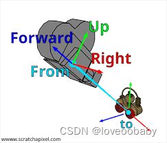
OpenGL本身没有摄像机(Camera)的概念,但我们为了产品上的需求与编程上的方便,一般会抽象一个摄像机组件。摄像机类似于人眼,可以建立一个本地坐标系。相机的位置是坐标原点,摄像机的朝向Forward是摄像机看的方向,再给定向上的Up轴即可建立本地坐标系。然后,可以通过矩阵将世界坐标系的物体变换到摄像机坐标系中,这个矩阵称为视图矩阵。通过改变摄像机的本地坐标系,可以产生场景漫游的效果。

1. 视图矩阵公式
视图矩阵是将物体坐标从世界空间坐标变换到相机本地坐标系中。计算视图矩阵需给定摄像机的位置 e y e \mathbf{eye} eye,焦点位置 t o \mathbf{to} to, Forward与Up所在平面的内的矢量 Y Y Y ,注意Y可以不与Forward垂直,我们可以通过叉乘获得摄像机的本地坐标系:
f w d = n o r m a l i z e ( e y e − t o ) r i g h t = n o r m a l i z e ( Y × f w d ) u p = n o r m a l i z e ( f w d × r i g h t ) \begin{aligned} & \mathbf{fwd} = normalize(\mathbf{eye}-\mathbf{to}) \\& \mathbf{right}=normalize(Y\times \mathbf{fwd}) \\& \mathbf{up} = normalize(\mathbf{fwd}\times\mathbf{right})\end{aligned} fwd=normalize(eye−to)right=normalize(Y×fwd)up=normalize(fwd×right)

LookAt矩阵等于:
L o o k A t = [ s i d e x s i d e y s i d e z − s i d e ⋅ e y e u p x u p y u p z − u p ⋅ e y e f w d x f w d x f w d x − f w d ⋅ e y e 0 0 0 1 ] LookAt= \begin{bmatrix} \mathbf{side}_x & \mathbf{side}_y & \mathbf{side}_z & -\mathbf{side}\cdot \mathbf{eye}\\ \mathbf{up}_x & \mathbf{up}_y & \mathbf{up}_z & -\mathbf{up}\cdot \mathbf{eye}\\ \mathbf{fwd}_x & \mathbf{fwd}_x & \mathbf{fwd}_x & -\mathbf{fwd}\cdot \mathbf{eye}\\ 0& 0 & 0 & 1 \end{bmatrix} LookAt= sidexupxfwdx0sideyupyfwdx0sidezupzfwdx0−side⋅eye−up⋅eye−fwd⋅eye1
Overload中计算视图矩阵代码:
OvMaths::FMatrix4 OvMaths::FMatrix4::CreateView(const float p_eyeX, const float p_eyeY, const float p_eyeZ, const float p_lookX, const float p_lookY, const float p_lookZ, const float p_upX, const float p_upY, const float p_upZ)
{
	const OvMaths::FVector3 eye(p_eyeX, p_eyeY, p_eyeZ); // 摄像机位置
	const OvMaths::FVector3 look(p_lookX, p_lookY, p_lookZ); // 摄像机焦点
	const OvMaths::FVector3 up(p_upX, p_upY, p_upZ); // 摄像机up

	const OvMaths::FVector3 forward(eye - look); // 摄像机的Z轴
	FVector3::Normalize(forward);

	// cross得到right轴
	const OvMaths::FVector3 upXForward(OvMaths::FVector3::Cross(up, forward));
	FVector3::Normalize(upXForward);

	// cross得到Up轴,等价于Y轴
	const OvMaths::FVector3 v(OvMaths::FVector3::Cross(forward, upXForward));

	OvMaths::FMatrix4 View;

	View.data[0] = upXForward.x;
	View.data[1] = upXForward.y;
	View.data[2] = upXForward.z;
	View.data[3] = -OvMaths::FVector3::Dot(eye, upXForward);

	View.data[4] = v.x;
	View.data[5] = v.y;
	View.data[6] = v.z;
	View.data[7] = -OvMaths::FVector3::Dot(eye, v);

	View.data[8] = forward.x;
	View.data[9] = forward.y;
	View.data[10] = forward.z;
	View.data[11] = -OvMaths::FVector3::Dot(eye, forward);

	return View;
}
2. 投影矩阵
投影是将物体的光线投射到相机的近平面上,将3D物体变成2D图像,是将相机坐标空间转换到屏幕空间,类似于真实相机的曝光过程。投影有两种透视投影与正交投影。
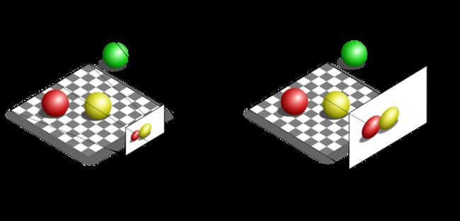
透视投影:通过透视概念模仿我们看到的真实世界的方式,尝试让2D图像看起来像是3D的。物体近大远小,这样3D空间中有的平行线看起来就不再平行。
正投影:与透视投影相反,在视锥体中的物体不因其距离相机远近做任何调整,直接进行投影。正投影在CAD软件中使用广泛。
透视投影矩阵:
[ 2 Z n e a r R − L 0 R + L R − L 0 0 2 Z n e a r T − B T + B T − B 0 0 0 − Z f a r + Z n e a r Z f a r − Z n e a r − 2 Z n e a r Z f a r Z f a r − Z n e a r 0 0 − 1 0 ] \begin{bmatrix} \frac{2Z_{near}}{R-L} & 0 & \frac{R+L}{R-L} & 0\\ 0 & \frac{2Z_{near}}{T-B} & \frac{T+B}{T-B} & 0\\ 0 & 0 & -\frac{Z_{far}+Z_{near}}{Z_{far}-Z_{near}} & -\frac{2Z_{near}Z_{far}}{Z_{far}-Z_{near}} \\ 0 & 0 & -1 & 0 \end{bmatrix} R−L2Znear0000T−B2Znear00R−LR+LT−BT+B−Zfar−ZnearZfar+Znear−100−Zfar−Znear2ZnearZfar0
其中:
Z n e a r 、 Z f a r 是相机位置到近平面、远平面的距离 Z_{near}、Z_{far}是相机位置到近平面、远平面的距离 Znear、Zfar是相机位置到近平面、远平面的距离
R、L–投影平面左右边界的X坐标
T、B–投影平面上下边界的Y坐标
Overload中计算透视投影矩阵的代码:
OvMaths::FMatrix4 OvMaths::FMatrix4::CreateFrustum(const float p_left, const float p_right, const float p_bottom, const float p_top, const float p_zNear, const float p_zFar)
{
	const float maxView = 2.0f * p_zNear;
	const float width = p_right - p_left;
	const float height = p_top - p_bottom;
	const float zRange = p_zFar - p_zNear;

	FMatrix4 Frustum;

	Frustum.data[0] = maxView / width;
	Frustum.data[5] = maxView / height;
	Frustum.data[2] = (p_right + p_left) / width;
	Frustum.data[6] = (p_top + p_bottom) / height;
	Frustum.data[10] = (-p_zFar - p_zNear) / zRange;
	Frustum.data[14] = -1.0f;
	Frustum.data[11] = (-maxView * p_zFar) / zRange;
	Frustum.data[15] = 0.0f;

	return Frustum;
}
正投影矩阵:
[ 2 R − L 0 0 − R + L R − L 0 2 T − B 0 − T + B T − B 0 0 1 Z f a r − Z n e a r − Z n e a r Z f a r − Z n e a r 0 0 0 1 ] \begin{bmatrix} \frac{2}{R-L} & 0 & 0 & -\frac{R+L}{R-L} \\ 0 & \frac{2}{T-B} & 0 & -\frac{T+B}{T-B} \\ 0 & 0 & \frac{1}{Z_{far}-Z_{near}} & -\frac{Z_{near}}{Z_{far}-Z_{near}} \\ 0 & 0 & 0 & 1 \end{bmatrix} R−L20000T−B20000Zfar−Znear10−R−LR+L−T−BT+B−Zfar−ZnearZnear1
Overload中计算正投影矩阵的代码:
OvMaths::FMatrix4 OvMaths::FMatrix4::CreateOrthographic(const float p_size, const float p_aspectRatio, const float p_zNear, const float p_zFar)
{
    auto ortho = OvMaths::FMatrix4::Identity;

    const auto right = p_size * p_aspectRatio;
    const auto left = -right;

    const auto top = p_size;
    const auto bottom = -top;

    ortho(0, 0) = 2.0f / (right - left);
    ortho(1, 1) = 2.0f / (top - bottom);
    ortho(2, 2) = -2.0f / (p_zFar - p_zNear);
    ortho(0, 3) = -(right + left) / (right - left);
    ortho(1, 3) = -(top + bottom) / (top - bottom);
    ortho(2, 3) = -(p_zFar + p_zNear) / (p_zFar - p_zNear);
    ortho(3, 3) = 1.0f;

    return ortho;
}
3. 摄像机封装
Overload中摄像机类比较简单,主要是对上面两个矩阵计算的封装。每次就是的时候需传入摄像机的位置及转动四元数,计算完视图投影矩阵后保存到自己的字段中。代码比较简单,不再分析了。
