07 A B 从计数器到可控线性序列机
07. A.从计数器到可控线性序列机
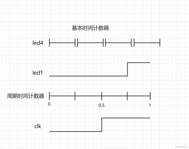
- 让LED灯按照亮0.25秒。灭0.75秒的状态循环亮灭
- 让LED灯按照亮0.25秒,灭0.5秒,亮0.75秒,灭1秒的状态循环亮灭
- 让LED灯按照指定的亮灭模式亮灭,亮灭模式未知,由用户随即指定。以0.25秒为一个变化周期,8个变化状态为一个循环。
- 让LED灯按照指定的亮灭模式亮灭,亮灭模式未知,由用户随机指定。8个变化状态为一个循环,每个变化状态的时间值可以根据不同的应用场景选择。
- 让多个LED灯按照设置的模式各自在一个变化循环内独立亮灭变化
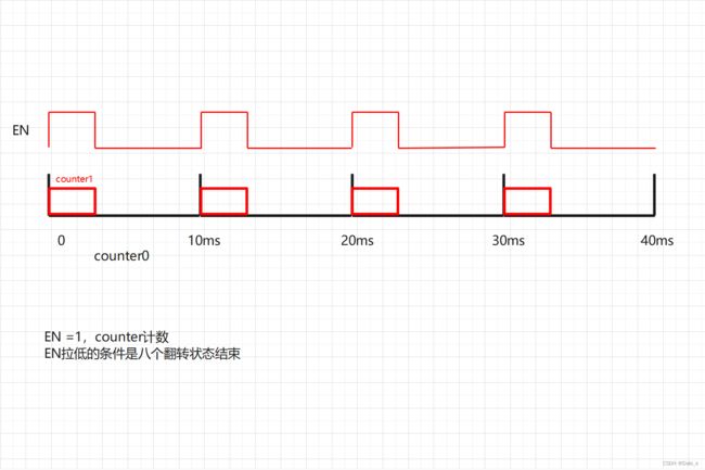
- 每隔10ms,让LED灯的一个8状态循环执行一次(每个状态的变化时间值小一点,方便测试,比如设置为10us)
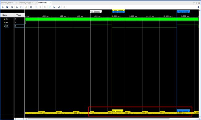
1.让LED灯按照亮0.25秒。灭0.75秒的状态循环亮灭
设计代码
module counter_led1(
	clk,
	rstn,
	led
);

	parameter MCNT = 50000000;
	input clk;
	input rstn;
	output reg led;

	reg[25:0] counter;
	always@(posedge clk or negedge rstn)
	if(!rstn)
		counter <= 0;
	else if(counter == MCNT-1)
		counter <= 0;
	else
		counter <= counter + 1'd1;

	always@(posedge clk or negedge rstn)
	if(!rstn)
		led <= 0;
	else if(counter == 3*MCNT/4 -1)
		led <= 1;
	else if(counter == MCNT - 1)
		led <= 0;

endmodule
仿真代码
`timescale 1ns / 1ns

module counter_led1_tb();

    reg clk;
    reg rstn;
    wire led;

    counter_led1 counter_led1_inst(
        .clk(clk),
        .rstn(rstn),
        .led(led)
    );
    defparam counter_led1_inst.MCNT = 50000;

    initial clk = 1;
    always #10 clk = !clk;

    initial begin
        rstn = 0;
        #201;
        rstn = 1;
        #2000000;
        $stop;
    end

endmodule
仿真波形
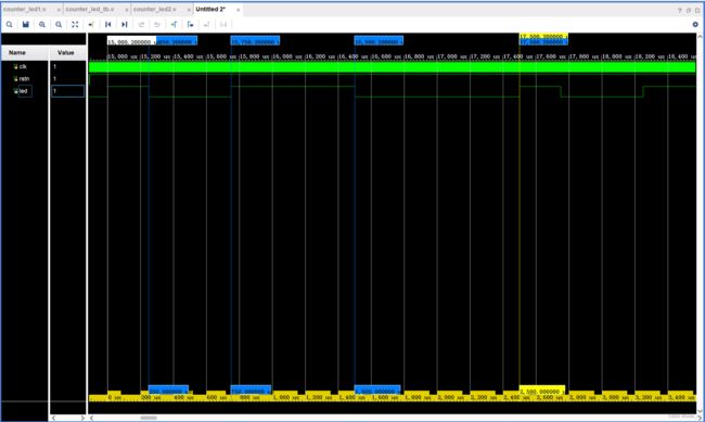
2.让LED灯按照亮0.25秒,灭0.5秒,亮0.75秒,灭1秒的状态循环亮灭
设计代码
module counter_led2(
	clk,
	rstn,
	led
);

	parameter MCNT = 1250000000;
	input clk;
	input rstn;
	output reg led;

	reg[25:0] counter;
	always@(posedge clk or negedge rstn)
	if(!rstn)
		counter <= 0;
	else if(counter == MCNT-1)
		counter <= 0;
	else
		counter <= counter + 1'd1;

	always@(posedge clk or negedge rstn)
	if(!rstn)
		led <= 1;
	else if(counter == MCNT/10 -1)
		led <= 0;
	else if(counter == 3*MCNT/10 - 1)
		led <= 1;
    else if(counter == 6*MCNT/10 - 1)
		led <= 0;
	else if(counter == MCNT - 1)
		led <= 1;

endmodule
仿真代码
`timescale 1ns / 1ns

module counter_led2_tb();

    reg clk;
    reg rstn;
    wire led;

    counter_led2 counter_led1_inst(
        .clk(clk),
        .rstn(rstn),
        .led(led)
    );
    defparam counter_led1_inst.MCNT = 125000;

    initial clk = 1;
    always #10 clk = !clk;

    initial begin
        rstn = 0;
        #201;
        rstn = 1;
        #200000000;
        $stop;
    end

endmodule
仿真波形
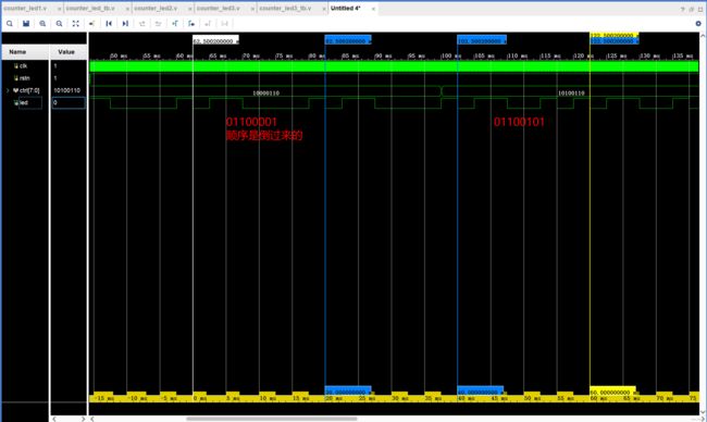
3.让LED灯按照指定的亮灭模式亮灭,亮灭模式未知,由用户随即指定。以0.25秒为一个变化周期,8个变化状态为一个循环。
思路:2秒为一个周期;有一个指定亮灭状态的输入端口,控制八种状态的亮灭,如果把亮灭看成1和0,那么就可以设计一个八位的控制亮灭状态的端口。
设计代码
- ctrl的输入端口不要加reg,ctrl虽然在always块内,但是没有被赋值,led被赋值。在tb里ctrl需要加reg。
- 当else if语句比较多是,我们可以将其替换为case语句,case语句的default不要忘记。
module counter_led3(
	clk,
	rstn,
	ctrl,
	led
);

	parameter MCNT = 1000000000;
	input clk;
	input rstn;
	input [7:0] ctrl; //注意:不能加reg
	output reg led;

	reg[25:0] counter;
	always@(posedge clk or negedge rstn)
	if(!rstn)
		counter <= 0;
	else if(counter == MCNT-1)
		counter <= 0;
	else
		counter <= counter + 1'd1;

//	always@(posedge clk or negedge rstn)
//	if(!rstn)
//		led <= 0;
//	else if(counter == MCNT/8 -1)
//		led <= ctrl[0];
//	else if(counter == 2*MCNT/8 - 1)
//		led <= ctrl[1];
//    else if(counter == 3*MCNT/8 - 1)
//		led <= ctrl[2];
//	else if(counter == 4*MCNT/8 - 1)
//		led <= ctrl[3];
//	else if(counter == 5*MCNT/8 - 1)
//		led <= ctrl[4];
//	else if(counter == 6*MCNT/8 - 1)
//		led <= ctrl[5];
//	else if(counter == 7*MCNT/8 - 1)
//		led <= ctrl[6];
//	else if(counter == MCNT - 1)
//		led <= ctrl[7];

	always@(posedge clk or negedge rstn)
	if(!rstn)
	    led <= 0;
	else case(counter)
	   1*MCNT/8 - 1 : led <= ctrl[0];
	   2*MCNT/8 - 1 : led <= ctrl[1];
	   3*MCNT/8 - 1 : led <= ctrl[2];
	   4*MCNT/8 - 1 : led <= ctrl[3];
	   5*MCNT/8 - 1 : led <= ctrl[4];
	   6*MCNT/8 - 1 : led <= ctrl[5];
	   7*MCNT/8 - 1 : led <= ctrl[6];
	   8*MCNT/8 - 1 : led <= ctrl[7];
	   default : led <= led;
	endcase

endmodule
3.1 仿真代码 (set as top)
`timescale 1ns / 1ns

module counter_led3_tb();

    reg clk;
    reg rstn;
    reg [7:0] ctrl;
    wire led;

    counter_led3 counter_led3_inst(
        .clk(clk),
        .rstn(rstn),
        .ctrl(ctrl),
        .led(led)
    );
    defparam counter_led3_inst.MCNT = 1000000;

    initial clk = 1;
    always #10 clk = !clk;

    initial begin
        rstn = 0;
        #201;
        rstn = 1;
        #2000;
        ctrl = 8'b10000110;
        #100000000;
        ctrl = 8'b10100110;
        #200000000;
        $stop;
    end

endmodule
仿真波形
总结:计数器不仅仅是一个计量整个时间的一个计数器,而且这个计数器里面的每一个计数值,他都可以作为整个这一段时间里面的一个刻度标尺,都可以拿来用
4.让LED灯按照指定的亮灭模式亮灭,亮灭模式未知,由用户随机指定。8个变化状态为一个循环,每个变化状态的时间值可以根据不同的应用场景选择。
设计文件
-
使用case语句时,每种情况的值必须是一个确定值,在这种情况下,我们必须修改代码,使各个状态由确定值来给定,而不是不确定的时间。
- timer的数据位宽与counter的数据位宽须保持一致
module counter_led4(
	clk,
	rstn,
	ctrl,
	times,
	led
);

	input clk;
	input rstn;
	input [7:0] ctrl;
	input [31:0] times;
	output reg led;

	reg[31:0] counter;
	always@(posedge clk or negedge rstn)
	if(!rstn)
		counter <= 0;
	else if(counter == times - 1'd1) //times的数据位宽与counter的数据位宽须保持一致
		counter <= 0;
	else
		counter <= counter + 1'd1;

    reg [2:0]counter2;
    always@(posedge clk or negedge rstn)
	if(!rstn)
		counter2 <= 0;
	else if(counter == times - 1'd1)
	   counter2 <= counter2 + 1'd1;


	always@(posedge clk or negedge rstn)
	if(!rstn)
	    led <= 0;
	else case(counter2)
	   0 : led <= ctrl[0];
	   1 : led <= ctrl[1];
	   2 : led <= ctrl[2];
	   3 : led <= ctrl[3];
	   4 : led <= ctrl[4];
	   5 : led <= ctrl[5];
	   6 : led <= ctrl[6];
	   7 : led <= ctrl[7];
	   default : led <= led;
	endcase

endmodule
仿真文件
`timescale 1ns / 1ns

module counter_led4_tb();

    reg clk;
    reg rstn;
    reg [7:0] ctrl;
    reg [31:0] times;
    wire led;

    counter_led4 counter_led4_inst(
        .clk(clk),
        .rstn(rstn),
        .ctrl(ctrl),
        .times(times),
        .led(led)
    );

    initial clk = 1;
    always #10 clk = !clk;

    initial begin
        rstn = 0;
        #201;
        rstn = 1;
        #2000;
        times = 32'd2500;
        ctrl = 8'b10000110;
        #100000000;
        times = 32'd10000;
        ctrl = 8'b10100110;
        #200000000;
        $stop;
    end

endmodule
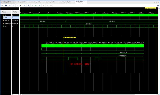
仿真波形
5.让多个LED灯按照设置的模式各自在一个变化循环内独立亮灭变化
- 在4的基础上多设置几个led灯输出端口即可,此处设置了3个led灯。SPI,IIC等都用到了该相似的原理。
module counter_led5(
	clk,
	rstn,
	ctrla,ctrlb,ctrlc,
	times,
	led1,led2,led3
);

	input clk;
	input rstn;
	input [7:0] ctrla,ctrlb,ctrlc;
	input [31:0] times;
	output reg led1,led2,led3;

	reg[31:0] counter;
	always@(posedge clk or negedge rstn)
	if(!rstn)
		counter <= 0;
	else if(counter == times - 1'd1)
		counter <= 0;
	else
		counter <= counter + 1'd1;

    reg [2:0]counter2;
    always@(posedge clk or negedge rstn)
	if(!rstn)
		counter2 <= 0;
	else if(counter == times - 1'd1)
	   counter2 <= counter2 + 1'd1;


	always@(posedge clk or negedge rstn)
	if(!rstn)
	    begin led1 <= 0; led2 <= 0; led3 <= 0; end
	else case(counter2)
	   0 : begin led1 <= ctrla[0]; led2 <= ctrlb[0]; led3 <= ctrlc[0]; end
	   1 : begin led1 <= ctrla[1]; led2 <= ctrlb[1]; led3 <= ctrlc[1]; end
	   2 : begin led1 <= ctrla[2]; led2 <= ctrlb[2]; led3 <= ctrlc[2]; end
	   3 : begin led1 <= ctrla[3]; led2 <= ctrlb[3]; led3 <= ctrlc[3]; end
	   4 : begin led1 <= ctrla[4]; led2 <= ctrlb[4]; led3 <= ctrlc[4]; end
	   5 : begin led1 <= ctrla[5]; led2 <= ctrlb[5]; led3 <= ctrlc[5]; end
	   6 : begin led1 <= ctrla[6]; led2 <= ctrlb[6]; led3 <= ctrlc[6]; end
	   7 : begin led1 <= ctrla[7]; led2 <= ctrlb[7]; led3 <= ctrlc[7]; end
	   default : begin led1 <= led1; led2 <= led2; led3 <= led3; end
	endcase

endmodule
07. B.受控线性序列机课题的实现
6.每隔10ms,让LED灯的一个8状态循环执行一次(每个状态的变化时间值小一点,方便测试,比如设置为10us)
原理图:
总结:通过控制en的状态就能控制计数器的计数,通过计数器的计数,来产生不同的序列,即从计数器到可控状态序列机。
设计代码
module counter_led6(
	clk,
	rstn,
	ctrl,
	times,
	led
);
	parameter MCNT = 500000;//10ms计数器
	input clk;
	input rstn;
	input [7:0] ctrl;
	input [31:0] times;
	output reg led;

	reg [31:0] counter0;
	//10ms周期计数器
	always@(posedge clk or negedge rstn)
	if(!rstn)
	   counter0 <= 0;
	else if(counter0 == MCNT - 1'd1)
	   counter0 <= 0;
	else
	   counter0 <= counter0 + 1'd1;

	reg EN;
	always@(posedge clk or negedge rstn)
	if(!rstn)
	   EN <= 0;
	else if(counter0 == 0)
	   EN <= 1'd1;
	else if(counter0 == 8*times - 1)
	   EN <= 0;

	reg[31:0] counter1;
	always@(posedge clk or negedge rstn)
	if(!rstn)
		counter1 <= 0;
	else if(EN == 1) begin
        if(counter1 == times - 1'd1)
            counter1 <= 0;
        else
            counter1 <= counter1 + 1'd1;
    end
    else
        counter1 <= 0;

    reg [2:0]counter2;
    always@(posedge clk or negedge rstn)
	if(!rstn)
		counter2 <= 0;
	else if(EN == 1)begin
	   if(counter1 == times - 1'd1)
	       counter2 <= counter2 + 1'd1;
	end
	else
	   counter2 <= 0;


	always@(posedge clk or negedge rstn)
	if(!rstn)
	    led <= 0;
	else case(counter2)
	   0 : led <= ctrl[0];
	   1 : led <= ctrl[1];
	   2 : led <= ctrl[2];
	   3 : led <= ctrl[3];
	   4 : led <= ctrl[4];
	   5 : led <= ctrl[5];
	   6 : led <= ctrl[6];
	   7 : led <= ctrl[7];
	   default : led <= led;
	endcase

endmodule
仿真代码
`timescale 1ns / 1ns

module counter_led6_tb();

    reg clk;
    reg rstn;
    reg [7:0] ctrl;
    reg [31:0] times;
    wire led;

    counter_led6 counter_led6_inst(
        .clk(clk),
        .rstn(rstn),
        .ctrl(ctrl),
        .times(times),
        .led(led)
    );

    initial clk = 1;
    always #10 clk = !clk;

    initial begin
        rstn = 0;
        #201;
        rstn = 1;
        #2000;
        times = 32'd500;
        ctrl = 8'b10000110;
        #100000000;
        ctrl = 8'b10100110;
        #200000000;
        $stop;
    end

endmodule
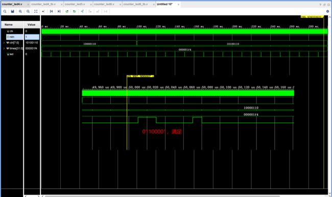
仿真波形
