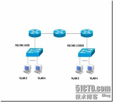
动态路由实验2
|
|
|
| 实验目的 |
本实验为交换与路由的综合实验,完成本实验,目的是为了掌握子网的划分、配置VLAN,以及在路由器上配置单臂路由来实现VLAN之间的路由;并且掌握在有子网的情况下使用动态路由协议实现子网的互通。 |
| 所需实验设备 |
1)3台路由器 2)2台交换机 3)2根交叉线 4)2根直连线 |
| 实验描述 |
1、划分子网 在192.168.1.0/25网段上包含3个VLAN,其中,VLAN 2中包含50台主机,VLAN 3和4中各包含25台主机;请写出子网划分的方案; 2、配置VLAN与单臂路由 1)在交换机上配置Vlan 2) 在路由器上配置单臂路由,实现交换机上各VLAN的互通; 3、配置RIP路由协议 在3台路由器上配置RIP路由协议,实现两台交换机上连接的各网段的互通。 4.交换机的转发原理 如果同在一个VLAN中的两台主机互相ping通后,其中一台主机修改本地ARP表中另一主机的MAC地址再ping,是否还内ping通?为什么? |
| 提交作业 |
1) 路由器与交换机的配置文件 2) 实验报告 |
子网划分:
因为2的2次方是4,所以192.168.1.0/25再借一位就可以了。子网掩码为255.255.255.192
Vlan2网络地址:192.168.1.0 可用IP:192.168.1.1―192.168.1.62 广播地址:192.168.1.63
Vlan3、vlan4网络地址:192.168.1.64 可用IP:192.168.1.65―192.168.1.126 广播地址:192.168.1.127
Vlan2网络地址:192.168.1.128 可用IP:192.168.1.129―192.168.1.190 广播地址:192.168.1.191
Vlan3、vlan4网络地址:192.168.1.192 可用IP:192.168.1.193―192.168.1.254 广播地址:192.168.1.255

思路:
(一)对于路由器:
1:命名
2:配置接口iP
3:配置单臂路由(对于路由器1和3)
4:配置RIP
(二)对于交换机:
1:命名
2:添加vlan
3:将指定端口添加到指定vlan
4:设置指定端口为trunk
(三)对于PC:
1:命名
2:禁用路由功能
3:设置IP
(四)查看命令:
查看基本配置:
show running-config
查看VLAN信息:
show vlan-switch
查看端口信息:
show interface 端口号
查看端口模式:
show interface 端口号 switchport
查看路由信息:
show ip route
查看路由协议:
show ip protocol
配置文档:
R1:
enable
config terminal
no ip domain-lookup //禁用DNS服务
hostname R1
interface f0/0 //激活端口
no shutdown
interface f0/0.1 //设置子端口协议和IP
encapsulation dot1q 2
ip address 192.168.1.1 255.255.255.192
interface f0/0.2 //设置子端口协议和IP
encapsulation dot1q 3
ip address 192.168.1.65 255.255.255.192
exit
interface f1/0
ip address 192.168.10.1 255.255.255.0 //设置IP
no shutdown
exit
router rip //设置RIPv2版本
network 192.168.1.0
network 192.168.10.0
version 2
no auto-summary
end
write
R2:
enable
config terminal
no ip domain-lookup //禁用DNS服务
hostname R2
interface f0/0
ip address 192.168.10.2 255.255.255.0 设置IP
no shutdown
interface f1/0
ip address 192.168.20.1 255.255.255.0 设置IP
no shutdown
exit
router rip //设置RIPv2版本
network 192.168.10.0
network 192.168.20.0
version 2
no auto-summary
end
write
R3:
enable
config terminal
no ip domain-lookup //禁用DNS服务
hostname R3
interface f0/0
ip address 192.168.20.2 255.255.255.0 //设置IP
no shutdown
interface f1/0.3 //设置子端口协议和IP
encapsulation dot1q 2
ip address 192.168.1.129 255.255.255.192
interface f1/0.4 //设置子端口协议和IP
encapsulation dot1q 3
ip address 192.168.1.193 255.255.255.192
exit
interface f1/0 //激活端口
no shutdown
exit
router rip //设置RIPv2版本
network 192.168.1.128
network 192.168.20.0
version 2
no auto-summary
end
write
SW1:
enable
config terminal
hostname SW1
exit
vlan database //添加vlan
vlan 2
vlan 3
exit
config terminal
interface f0/0
switchport mode trunk //设置trunk
interface f0/2
switchport access vlan 2 //将指定端口添加到相应的vlan
interface f0/3
switchport access vlan 3 //将指定端口添加到相应的vlan
end
write
SW2:
enable
config terminal
hostname SW2
exit
vlan database //添加vlan
vlan 2
vlan 3
exit
config terminal
interface f0/0
switchport mode trunk //设置trunk
interface f0/2
switchport access vlan 2 //将指定端口添加到相应的vlan
interface f0/3
switchport access vlan 3 //将指定端口添加到相应的vlan
end
write
pc1:
enable
config terminal
no ip routing //禁用路由功能
hostname PC1
interface f0/0
ip address 192.168.1.20 255.255.255.192 //设置IP
no shutdown
end
write
pc2:
enable
config terminal
no ip routing //禁用路由功能
hostname PC2
interface f0/0
ip address 192.168.1.100 255.255.255.192 //设置IP
no shutdown
end
write
pc3:
enable
config terminal
no ip routing //禁用路由功能
hostname PC3
interface f0/0
ip address 192.168.1.168 255.255.255.192 //设置IP
no shutdown
end
write
pc4:
enable
config terminal
no ip routing //禁用路由功能
hostname PC4
interface f0/0
ip address 192.168.1.200 255.255.255.192 //设置IP
no shutdown
end
write
出现的错误:
由于一开始没有注意SW2 的接口是F1/0。所以在设置的时候把子端口设置错误了。。。应该是
F1/0.2的。。。
再一个这个子端口F1/0.2是个虚拟的端口。。。而且在这个图中R1和R3连接SW的端口可以不设置IP.!
测试图片:


