Noise, being a pseudorandom artist
In this tutorial you will create your own texture, and make it interesting with pseudorandom noise.You'll learn to
- Create and fill a texture;
- Visualize a slice through world space;
- Use delegates;
- Use a hash array for 1D, 2D, and 3D hashing;
- Compute Value noise;
- Compute Perlin noise;
- Create fractal noise;
- Use a gradient.
This tutorial builds on the foundation laid by previous tutorials. If you completed the Curves and Splines tutorial then you're good to go.
This tutorial has been made with Unity 4.5.2. It might not work for older versions.
 A slice through colored 3D Perlin noise.
Creating a Texture
Let's begin by creating a default quad object. This object has a mesh with two triangles that form a square with a width and height of one unit each.
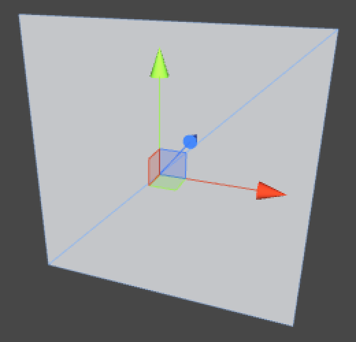
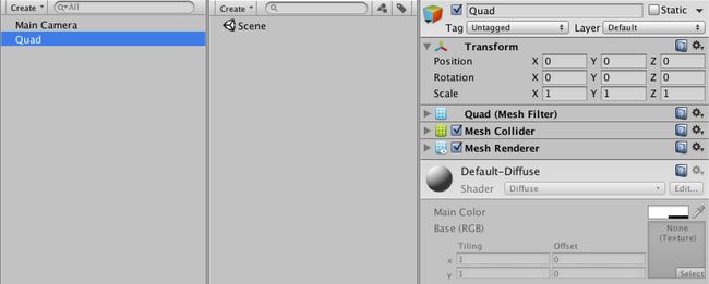 A bland quad.
We can make the quad more interesting by giving it a material with a nice texture. We could use any image as a texture, but we're going to create one procedurally. For this we need a material to assign the texture to, so create one and have the quad use it instead of the default. Then create a TextureCreator component script and attach it to the quad as well.
- Why not use a procedural shader?
using UnityEngine;

public class TextureCreator : MonoBehaviour {
}
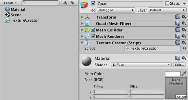 Quad with custom material and texture creator.
To create a texture, we need to know how many pixels it should have. We'll create a square texture, so we can control its size with a single resolution variable. Let's give it a default of 256.
- Why 256?
public int resolution = 256;
We will create the texture when our component awakens. As we won't use transparency, the texture's format is RGB. The fourth argument of the texture's constructor indicates that we want to use mipmaps. We also give it a descriptive name.
Then we grab the MeshRenderer component of the game object. Because we're only using it with our quad object, it should exist so we directly assign the texture to its material.
- What does RGB24 mean?
- What are mipmaps?
	private Texture2D texture;

	private void Awake () {
		texture = new Texture2D(resolution, resolution, TextureFormat.RGB24, true);
		texture.name = "Procedural Texture";
		GetComponent<MeshRenderer>().material.mainTexture = texture;
	}
 Quad awakens with a texture in play mode.
Without filling the texture this doesn't make much sense. So let's add a FillTexture method that uses a double loop to make all the pixels red.
After setting the pixels, you have to call the texture's Apply method otherwise the changes won't show up.
	private void Awake () {
		texture = new Texture2D(resolution, resolution, TextureFormat.RGB24, true);
		texture.name = "Procedural Texture";
		GetComponent<MeshRenderer>().material.mainTexture = texture;
		FillTexture();
	}

	private void FillTexture () {
		for (int y = 0; y < resolution; y++) {
			for (int x = 0; x < resolution; x++) {
				texture.SetPixel(x, y, Color.red);
			}
		}
		texture.Apply();
	}
A red quad.
Don't like red? What about green? Go ahead and change the color, but do this while still in play mode.
	private void FillTexture () {
		for (int y = 0; y < resolution; y++) {
			for (int x = 0; x < resolution; x++) {
				texture.SetPixel(x, y, Color.green);
			}
		}
		texture.Apply();
	}
You will see that Unity recompiles the code just fine, but the texture stays red. This is because Awake isn't called again when there is a recompile. However, there is another option.
The OnEnable method is called directly after Awake, each time the component is activated. This also happens after a recompile while in play mode. So if we use OnEnable instead of Awake, our quad will turn green without having to toggle play mode.
	private void OnEnable () {
		texture = new Texture2D(resolution, resolution, TextureFormat.RGB24, true);
		texture.name = "Procedural Texture";
		GetComponent<MeshRenderer>().material.mainTexture = texture;
		FillTexture();
	}
A flat color is not interesting at all. Instead, we can use a pixel's coordinates to define its color. We can directly put x in the red channel and y in the green channel, leaving blue at zero. However, as color channels are defined in a 0–1 range, we have to divide by the resolution, which we can define outside the loop.
- Why a 0–1 range?
	private void FillTexture () {
		float stepSize = 1f / resolution;
		for (int y = 0; y < resolution; y++) {
			for (int x = 0; x < resolution; x++) {
				texture.SetPixel(x, y, new Color(x * stepSize, y * stepSize, 0f));
			}
		}
		texture.Apply();
	}
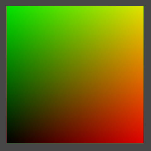 Colored with texture coordinates.
Have now visualized the texture coordinates, also known as uv coordinates. But there is something weird going on at the edge of the texture. It is easier to see this when using a smaller resolution. Unfortunately, changing the resolution has no effect while in play mode.
Let's create a custom inspector for our component so we can easily detect any change to our component. It simply draws the default inspector and checks for changes. If a change happened while we are also in play mode, we should call FillTexture.
 Adding an inspector.
using UnityEditor;
using UnityEngine;

[CustomEditor(typeof(TextureCreator))]
public class TextureCreatorInspector : Editor {

	public override void OnInspectorGUI () {
		EditorGUI.BeginChangeCheck();
		DrawDefaultInspector();
		if (EditorGUI.EndChangeCheck() && Application.isPlaying) {
			(target as TextureCreator).FillTexture();
		}
	}
}
Of course this means that we have to make FillTexture public. And it should also check whether the resolution has changed, and if so resize the texture. Let's also constrain it to some reasonable range, like 2–512.
	[Range(2, 512)]
	public int resolution = 256;

	public void FillTexture () {
		if (texture.width != resolution) {
			texture.Resize(resolution, resolution);
		}
		float stepSize = 1f / resolution;
		for (int y = 0; y < resolution; y++) {
			for (int x = 0; x < resolution; x++) {
				texture.SetPixel(x, y, new Color(x * stepSize, y * stepSize, 0f));
			}
		}
		texture.Apply();
	}
Scrubbing the resolution, still in play mode.
We can do even better than that. We can also respond to undo and redo actions, while in play mode. We can do this by registering a method to the Undo.undoRedoPerformed delegate. So we create such a method and place the check whether we're in play mode there as well.
TextureCreatorInspector has to register the method when it is enabled, but should also unregister it when it is disabled. So add the appropriate methods, and also store a reference to our creator so we don't have to cast it every time.
- What's a delegate?
	private TextureCreator creator;

	private void OnEnable () {
		creator = target as TextureCreator;
		Undo.undoRedoPerformed += RefreshCreator;
	}

	private void OnDisable () {
		Undo.undoRedoPerformed -= RefreshCreator;
	}

	private void RefreshCreator () {
		if (Application.isPlaying) {
			creator.FillTexture();
		}
	}

	public override void OnInspectorGUI () {
		EditorGUI.BeginChangeCheck();
		DrawDefaultInspector();
		if (EditorGUI.EndChangeCheck()) {
			RefreshCreator();
		}
	}
 UV colors at resolution 8.
Back to our weird edges! At a resolution of 8, it is a lot easier to see what is happening. At the edges, colors from opposite sides are blended together. This happens because the default wrap mode of textures is to repeat themselves. We can get rid of this by having TextureCreator set its texture's wrap mode to clamp.
	private void OnEnable () {
		texture = new Texture2D(resolution, resolution, TextureFormat.RGB24, true);
		texture.name = "Procedural Texture";
		texture.wrapMode = TextureWrapMode.Clamp;
		GetComponent<MeshRenderer>().material.mainTexture = texture;
		FillTexture();
	}
 Clamped colors.
Why are we actually seeing a smooth color transition, if our texture is only 8 by 8 pixels? This is because the default filter mode is bilinear. Let's compare this with point filtering.
	private void OnEnable () {
		texture = new Texture2D(resolution, resolution, TextureFormat.RGB24, true);
		texture.name = "Procedural Texture";
		texture.wrapMode = TextureWrapMode.Clamp;
		texture.filterMode = FilterMode.Point;
		GetComponent<MeshRenderer>().material.mainTexture = texture;
		FillTexture();
	}
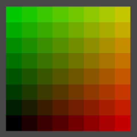 Point filtering.
Now we see 64 blocks of solid colors, although an optical illusion will make it look like they contain gradients.
For each rendered pixel, point filter mode selects the color of the texture pixel that it covers. This visually tells us where the centers of our texture's pixels are, right in the middle of those squares. Bilinear filtering linearly interpolates between those pixel centers. Let's compare them again at a resolution of 2.
	private void OnEnable () {
		texture = new Texture2D(resolution, resolution, TextureFormat.RGB24, true);
		texture.name = "Procedural Texture";
		texture.wrapMode = TextureWrapMode.Clamp;
		texture.filterMode = FilterMode.Bilinear;
		GetComponent<MeshRenderer>().material.mainTexture = texture;
		FillTexture();
	}
 2 by 2, point and bilinear filtering.
So the center of the bottom left texture pixel has uv coordinates (0.25, 0.25). The top right is at (0.75, 0.75). However, in FillTexture we currently compute the colors for (0, 0) and (0.5, 0.5) respectively. This means we are calculating the colors at the bottom left corners of our pixels, instead of their centers. To fix this, we need to add half a pixel to x and y.
	public void FillTexture () {
		if (texture.width != resolution) {
			texture.Resize(resolution, resolution);
		}
		float stepSize = 1f / resolution;
		for (int y = 0; y < resolution; y++) {
			for (int x = 0; x < resolution; x++) {
				texture.SetPixel(x, y, new Color((x + 0.5f) * stepSize, (y + 0.5f) * stepSize, 0f));
			}
		}
		texture.Apply();
	}
2 by 2, correctly centered.
You can let the pattern repeat inside the texture by using the remainder operator. For example, by taking the remainder of dividing by 0.1 we end up going from 0 to just below 0.1 ten times. To keep the result visible, we simply scale it up by ten.
				texture.SetPixel(x, y,
					new Color((x + 0.5f) * stepSize % 0.1f, (y + 0.5f) * stepSize % 0.1f, 0f) * 10f);
 Repeating the pattern.
After doing that, zoom out the scene view to see what happens. Especially when zooming out far, you'll see the image gets sharper and then suddenly blurrier a few times. This happens because of mipmapping, which we have enabled. We can disable this by setting our texture's fourth constructor argument to false.
	private void OnEnable () {
		texture = new Texture2D(resolution, resolution, TextureFormat.RGB24, false);
		texture.name = "Procedural Texture";
		texture.wrapMode = TextureWrapMode.Clamp;
		texture.filterMode = FilterMode.Bilinear;
		GetComponent<MeshRenderer>().material.mainTexture = texture;
		FillTexture();
	}
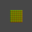 Zoomed out, with and without mipmapping.
Mipmapping definitely produces better results when zoomed out, but it is unfortunate that there is a harsh transition between successive mipmap levels. You can also see some of these transitions when looking at the quad from a sharp angle, especially when in motion.
The quad will probably turn dark in the scene view when seen at an angle, because of the way scene view lighting works. To temporarily solve this, you can enable lighting in the scene view by toggling the light button in its toolbar, and create a directional light.
Fortunately, there is a trilinear filtering option which also interpolated between adjacent mipmap levels, so let's use that.
	private void OnEnable () {
		texture = new Texture2D(resolution, resolution, TextureFormat.RGB24, true);
		texture.name = "Procedural Texture";
		texture.wrapMode = TextureWrapMode.Clamp;
		texture.filterMode = FilterMode.Trilinear;
		GetComponent<MeshRenderer>().material.mainTexture = texture;
		FillTexture();
	}
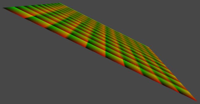
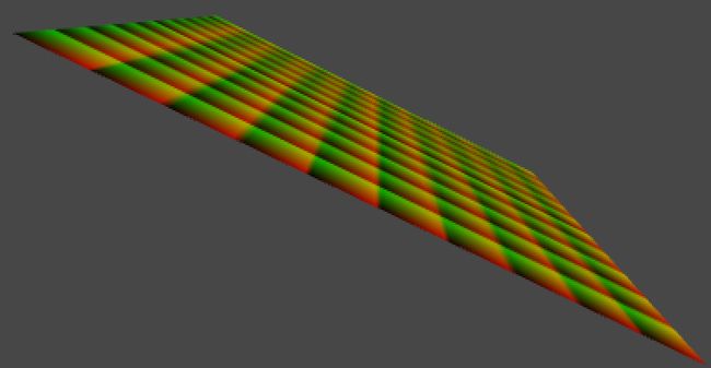 Bilinear and trilinear filtering.
With trilinear filtering, our texture is now displayed smoothly, without sharp transitions. The downside is that it gets fuzzy quick when viewed at an angle. To improve this, we can use anisotropic filtering. It is enabled by setting the texture's aniso level to a value higher than one. Let's set it to nine, because that's the highest level.
- What's anisotropic filtering?
	private void OnEnable () {
		texture = new Texture2D(resolution, resolution, TextureFormat.RGB24, true);
		texture.name = "Procedural Texture";
		texture.wrapMode = TextureWrapMode.Clamp;
		texture.filterMode = FilterMode.Trilinear;
		texture.anisoLevel = 9;
		GetComponent<MeshRenderer>().material.mainTexture = texture;
		FillTexture();
	}
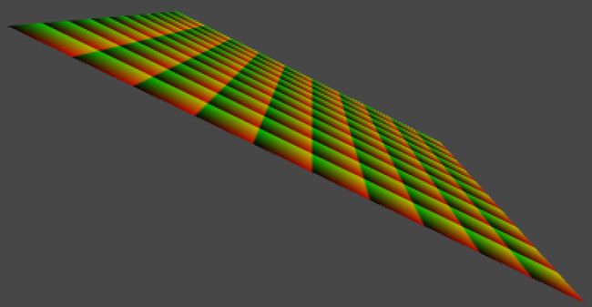 Anisotropic filtering.
Let's leave our texture with these settings. But while we're at it, we shouldn't create a new one each time our component is enabled. So add a check for that.
	private void OnEnable () {
		if (texture == null) {
			texture = new Texture2D(resolution, resolution, TextureFormat.RGB24, true);
			texture.name = "Procedural Texture";
			texture.wrapMode = TextureWrapMode.Clamp;
			texture.filterMode = FilterMode.Trilinear;
			texture.anisoLevel = 9;
			GetComponent<MeshRenderer>().material.mainTexture = texture;
		}
		FillTexture();
	}
Visualizing World Space
Right now we are visualizing the uv coordinates of our texture's space, which is always the same. We can change this so we are visualizing world coordinates instead. Our quad will act like a measuring device for world coordinates.
First, let's define the local coordinates of the four corners of our quad. Because it is centered on its own origin, these are (-0.5,-0.5,0), (0.5,-0.5,0), (-0.5,0.5,0), and (0.5,0.5,0). We name them pointxy, where x is 0 for the left side and 1 for the right size. Likewise, y is 0 for the bottom side and 1 for the top side.
	public void FillTexture () {
		if (texture.width != resolution) {
			texture.Resize(resolution, resolution);
		}

		Vector3 point00 = new Vector3(-0.5f,-0.5f);
		Vector3 point10 = new Vector3( 0.5f,-0.5f);
		Vector3 point01 = new Vector3(-0.5f, 0.5f);
		Vector3 point11 = new Vector3( 0.5f, 0.5f);

		float stepSize = 1f / resolution;
		for (int y = 0; y < resolution; y++) {
			for (int x = 0; x < resolution; x++) {
				texture.SetPixel(x, y,
					new Color((x + 0.5f) * stepSize % 0.1f, (y + 0.5f) * stepSize % 0.1f, 0f) * 10f);
			}
		}
		texture.Apply();
	}
Second, we linearly interpolate these corners inside our loops. We do this in two steps.
Step one is to interpolate between the bottom left and top left corner based on y, which gives us a point on the left side. We name it point0. We do the same thing for the right side, naming the result point1.
Step two is to interpolate between these intermediate points based on x.
We have now used bilinear interpolation to find the final point, which we directly convert into a color.
		float stepSize = 1f / resolution;
		for (int y = 0; y < resolution; y++) {
			Vector3 point0 = Vector3.Lerp(point00, point01, (y + 0.5f) * stepSize);
			Vector3 point1 = Vector3.Lerp(point10, point11, (y + 0.5f) * stepSize);
			for (int x = 0; x < resolution; x++) {
				Vector3 point = Vector3.Lerp(point0, point1, (x + 0.5f) * stepSize);
				texture.SetPixel(x, y, new Color(point.x, point.y, point.z));
			}
		}
 Local coordinates.
We are now visualizing the local coorindates of our quad. So it is always black at the center. It is also black at the bottom left because those coordinates are negative and colors are clamped to the 0–1 range.
To visualize world-space coorinates instead, all we have to do is transform our four corner points to world space.
		Vector3 point00 = transform.TransformPoint(new Vector3(-0.5f,-0.5f));
		Vector3 point10 = transform.TransformPoint(new Vector3( 0.5f,-0.5f));
		Vector3 point01 = transform.TransformPoint(new Vector3(-0.5f, 0.5f));
		Vector3 point11 = transform.TransformPoint(new Vector3( 0.5f, 0.5f));
However, moving the quad currently doesn't cause the texture to change. We could add an Update method and simply fill our texture every frame. That will ensure that the texture is always up to date. Let's do this, but also check whether our quad's transform has actually changed. That way the texture is only refilled when necessary.
- How does
hasChangedwork?
	private void Update () {
		if (transform.hasChanged) {
			transform.hasChanged = false;
			FillTexture();
		}
	}
Now you can move, rotate, and even scale the quad and it will immediately change its color to match to world position it occupies.
Making Noise
Visualizing world coordinates isn't very interesting. Instead, we could visualize some mathematical formula, like a sine wave. Such formulas are regular and predictable, while we often need irregular and unpredictale shapes. For example to simulate dirt, rust, fabric irregularities, and other patterns that appear random to us.
A naive approach is to simply use Random.value. Unity's random methods use a function that computes its next number based on some of its previous numbers, in such a way that we cannot easily see a pattern.
		for (int y = 0; y < resolution; y++) {
			Vector3 point0 = Vector3.Lerp(point00, point01, (y + 0.5f) * stepSize);
			Vector3 point1 = Vector3.Lerp(point10, point11, (y + 0.5f) * stepSize);
			for (int x = 0; x < resolution; x++) {
				Vector3 point = Vector3.Lerp(point0, point1, (x + 0.5f) * stepSize);
				texture.SetPixel(x, y, Color.white * Random.value);
			}
		}
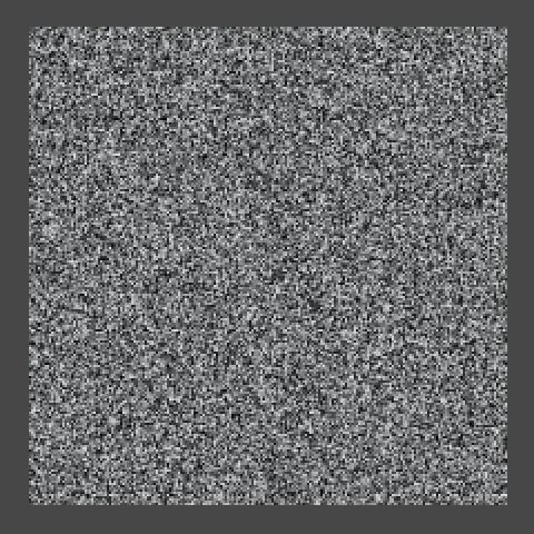 Noise.
The result sure looks random. Unfortunately, it is so random that we get a different result each time the texture is filled. This is because the random sequence continues from where it ended after the previous texture fill. But we don't want this, we actually want pseudorandom noise that produces the same results each time. We can solve this by choosing a fixed initial value – knows as a seed – before filling the texture.
		float stepSize = 1f / resolution;
		Random.seed = 42;
		for (int y = 0; y < resolution; y++) {
			Vector3 point0 = Vector3.Lerp(point00, point01, (y + 0.5f) * stepSize);
			Vector3 point1 = Vector3.Lerp(point10, point11, (y + 0.5f) * stepSize);
			for (int x = 0; x < resolution; x++) {
				Vector3 point = Vector3.Lerp(point0, point1, (x + 0.5f) * stepSize);
				texture.SetPixel(x, y, Color.white * Random.value);
			}
		}
Now we get the same pattern each time. That is, until we change the resolution of the image. The value sequence does not depend on the pixel uv coordinates, but on the order in which the pixels are filled. The left side of the bottom row stays the same as you increase the resolution, but the rest of the sequence shifts as it gets applied to longer rows.

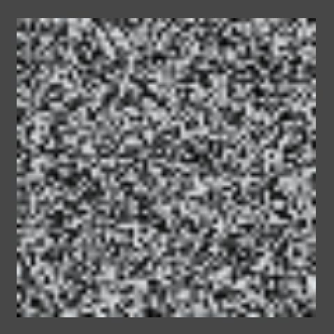 The same sequence at resolutions 32, 64, and 128.
This won't do. We want our pattern to be independent of the resolution and order in which we fill our texture. It is time to write our own pseudorandom noise code!
Create a script named Noise and turn it into a static class. This will become our noise library.
using UnityEngine;

public static class Noise {
}
What we want is a method that, given point in 3D space, returns a seemingly random value. Let's just return the point's x coordinate for now.
	public static float Value (Vector3 point) {
		return point.x;
	}
Now we can change the FillTexture method of TextureCreator so it uses this new method. Also remove the assigment to Random.seed, because we no longer need it.
		float stepSize = 1f / resolution;
		for (int y = 0; y < resolution; y++) {
			Vector3 point0 = Vector3.Lerp(point00, point01, (y + 0.5f) * stepSize);
			Vector3 point1 = Vector3.Lerp(point10, point11, (y + 0.5f) * stepSize);
			for (int x = 0; x < resolution; x++) {
				Vector3 point = Vector3.Lerp(point0, point1, (x + 0.5f) * stepSize);
				texture.SetPixel(x, y, Color.white * Noise.Value(point));
			}
		}
Of course Noise.Value doesn't produce anything that looks like noise yet. But how do we generate such a pattern? Let's start very simple, with alternating stripes of black and white.
We can generate vertical stripes by casting the point's x coordinate to an integer, discarding its fractional part. Then we return 1 when the integer is odd, otherwise we return 0. We could do this by returning the remainder of dividing our integer by two.
	public static float Value (Vector3 point) {
		int i = (int)point.x;
		return i % 2;
	}
We should now see unit-length stripes on our quad, but only if we move it far enough to the right or increase its scale. We could get a better look at our pattern if we scaled it down. Let's do so by adding a frequency parameter to our method. The idea is that if the frequency is doubled, the pattern changes twice as fast. We can do this by simply multiplying the point by the frequency.
	public static float Value (Vector3 point, float frequency) {
		point *= frequency;
		int i = (int)point.x;
		return i % 2;
	}
Then add a public frequency variable to TextureCreator so it becomes configurable, and pass it to the noise method.
	public float frequency = 1f;

	public void FillTexture () {
		if (texture.width != resolution) {
			texture.Resize(resolution, resolution);
		}

		Vector3 point00 = transform.TransformPoint(new Vector3(-0.5f,-0.5f));
		Vector3 point10 = transform.TransformPoint(new Vector3( 0.5f,-0.5f));
		Vector3 point01 = transform.TransformPoint(new Vector3(-0.5f, 0.5f));
		Vector3 point11 = transform.TransformPoint(new Vector3( 0.5f, 0.5f));

		float stepSize = 1f / resolution;
		for (int y = 0; y < resolution; y++) {
			Vector3 point0 = Vector3.Lerp(point00, point01, (y + 0.5f) * stepSize);
			Vector3 point1 = Vector3.Lerp(point10, point11, (y + 0.5f) * stepSize);
			for (int x = 0; x < resolution; x++) {
				Vector3 point = Vector3.Lerp(point0, point1, (x + 0.5f) * stepSize);
				texture.SetPixel(x, y, Color.white * Noise.Value(point, frequency));
			}
		}
		texture.Apply();
	}
Half the stripes at frequency 10.
Assuming the quad is not transformed, at a frequency of 10 we can see a total of five stripes – three black and two white – on the positive side, but nothing on the negative side. That's because the remainder on the left side is either zero or negative one. So we should return the absolute value of the remainder.
Alternatively, because integers are stored as binary numbers, we can look at the least significant bit to determine whether the number is odd. This can be done with the bitwise-and operator, discarding everything except the least significant bit. As a bonus, this approach is also very fast.
- How does
&work?
return i & 1;
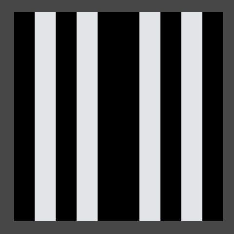 Stripes with a gap.
The stripes now appear on both sides, but the pattern is mirrored, which causes a gap. As casting to an integer discards the fractional part of a float, it effectively rounds down on the positive side, while rounding up on the negative side. We could solve this by subtracting one when on the negative side. But there's also a convenient method that does this for us, so let's use that.
		int i = Mathf.FloorToInt(point.x);
		return i & 1;
 Correct stripe pattern.
Now that we have produced a correct pattern by partitioning space, we can build our noise on top of that. Such noice is known as lattice noise, because it divides space into a regular lattice. In this case it's regular 1D intervals, while in 2D it would be a square grid and in 3D a cube grid.
The next step is to assign seemingly random values to each stripe coordinate, instead of just alternating black and white. This is done by using some function that converts any lattice coordinate into some other value. Such a function is known as a hash function, and there are many different flavors of those.
We will use a permutation array as our hashing method. This is simply an array containing a bunch of integers, let's use 0 through 7.
If we were to use our integer coordinate to index this array, we'd get a value up to seven. Let's do that and scale the result so we stay in the 0–1 range.
	private static int[] hash = {
		0, 1, 2, 3, 4, 5, 6, 7
	};

	public static float Value (Vector3 point, float frequency) {
		point *= frequency;
		int i = Mathf.FloorToInt(point.x);
		return hash[i] / 7f;
	}
However, this will result in an error as i goes out of the index range of our array when it goes above seven or below zero. Because our array has a length of eight, if we limit ourselves to the three least significant bits of i, the index will wrap around exactly when it needs to.
		point *= frequency;
		int i = Mathf.FloorToInt(point.x);
		i &= 7;
		return hash[i] / 7f;
 Using a hash array at resolution 32.
We now see up to eight different colors, but the pattern is still obviously regular and repeating. Let's make it less obvious by shuffling the values inside the array. That will result in a different permutation of the same collection of numbers. This is why such an array is often named a permutation array or a permutation table.
	private static int[] hash = {
		4, 2, 7, 5, 1, 6, 3, 0
	};
 Using a different permutation.
The pattern now looks less regular, but it still clearly repeats. What would happen if we add another permutation of the same sequence to the array? As this increases our array's size to 16, we also need to add an additional bit to our bit mask.
	private static int[] hash = {
		4, 2, 7, 5, 1, 6, 3, 0, 1, 5, 3, 7, 2, 0, 4, 6
	};

	public static float Value (Vector3 point, float frequency) {
		point *= frequency;
		int i = Mathf.FloorToInt(point.x);
		i &= 15;
		return hash[i] / 7f;
	}
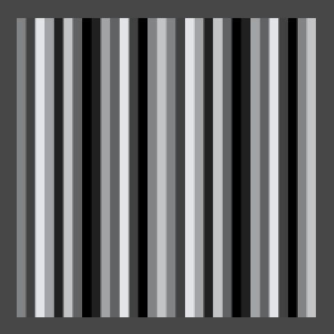 Using two permutations in one array.
We simply got a larger sequence that contains each value twice. We might as well make every value unique and increase our output resolution to 16 different values.
	private static int[] hash = {
		7, 3, 15, 8, 1, 6, 0, 2, 11, 5, 12, 4, 9, 14, 13, 10
	};

	public static float Value (Vector3 point, float frequency) {
		point *= frequency;
		int i = Mathf.FloorToInt(point.x);
		i &= 15;
		return hash[i] / 15f;
	}
16 distinct values.
The hash array will always produce a tiling pattern, but we only notice that when we see a large enough sampling of it. So let's increase its length to 256. If we also define the hash mask value as a constant, our method will work regardless of the array's size.
private static int[] hash = {
		151,160,137, 91, 90, 15,131, 13,201, 95, 96, 53,194,233,  7,225,
		140, 36,103, 30, 69,142,  8, 99, 37,240, 21, 10, 23,190,  6,148,
		247,120,234, 75,  0, 26,197, 62, 94,252,219,203,117, 35, 11, 32,
		 57,177, 33, 88,237,149, 56, 87,174, 20,125,136,171,168, 68,175,
		 74,165, 71,134,139, 48, 27,166, 77,146,158,231, 83,111,229,122,
		 60,211,133,230,220,105, 92, 41, 55, 46,245, 40,244,102,143, 54,
		 65, 25, 63,161,  1,216, 80, 73,209, 76,132,187,208, 89, 18,169,
		200,196,135,130,116,188,159, 86,164,100,109,198,173,186,  3, 64,
		 52,217,226,250,124,123,  5,202, 38,147,118,126,255, 82, 85,212,
		207,206, 59,227, 47, 16, 58, 17,182,189, 28, 42,223,183,170,213,
		119,248,152,  2, 44,154,163, 70,221,153,101,155,167, 43,172,  9,
		129, 22, 39,253, 19, 98,108,110, 79,113,224,232,178,185,112,104,
		218,246, 97,228,251, 34,242,193,238,210,144, 12,191,179,162,241,
		 81, 51,145,235,249, 14,239,107, 49,192,214, 31,181,199,106,157,
		184, 84,204,176,115,121, 50, 45,127,  4,150,254,138,236,205, 93,
		222,114, 67, 29, 24, 72,243,141,128,195, 78, 66,215, 61,156,180
	};

	private const int hashMask = 255;

	public static float Value (Vector3 point, float frequency) {
		point *= frequency;
		int i = Mathf.FloorToInt(point.x);
		i &= hashMask;
		return hash[i] * (1f / hashMask);
	}
 256 values, at frequency 32, 256, and 512.
This particular permutation is the same one that Ken Perlin uses in his reference implementations of his noise algorithm, which we'll cover later. Besides that, there is nothing special about it.
With this array it takes a while before we see it repeat. When using a frequency of 512 we can see that it repeats once, but at that point we can't even see the individual lines any more. You can increase the array size even more, or use other tricks to dramatically increase the period length, but 256 suffices for most cases.
Going Into Higher Dimensions
Let's extend this approach to two dimensions. Duplicate the Value method and add a 1D and a 2D suffix to them.
	public static float Value1D (Vector3 point, float frequency) {
		point *= frequency;
		int i = Mathf.FloorToInt(point.x);
		i &= hashMask;
		return hash[i] * (1f / hashMask);
	}

	public static float Value2D (Vector3 point, float frequency) {
		point *= frequency;
		int i = Mathf.FloorToInt(point.x);
		i &= hashMask;
		return hash[i] * (1f / hashMask);
	}
Then change TextureCreator.FillTexture so it uses the 2D version of our noise method.
texture.SetPixel(x, y, Color.white * Noise.Value2D(point, frequency));
Now we have to give the y coordinate the same treatment as the x coordinate. So add a second versions of the i variable, naming them ix and iy.
Instead of directly returning the hash of ix, we'll add it to iy and use that to index the hash array a second time. Of course, we need to make sure that their sum remains within bounds.
	public static float Value2D (Vector3 point, float frequency) {
		point *= frequency;
		int ix = Mathf.FloorToInt(point.x);
		int iy = Mathf.FloorToInt(point.y);
		ix &= hashMask;
		iy &= hashMask;
		return hash[(hash[ix] + iy) & hashMask] * (1f / hashMask);
	}
 2D hashing.
It looks pretty random, right? We are offseting the hash index off the y coordinate by the hash result of the x coordinate. But this means that the vertical patterns are all the same, they're just placed at different offsets. You can spot this in the image above if you know where to look. It contains two adjacent columns that are offset by exactly one step. This happens because the fourth and fifth numbers in the hash array are 91 and 90. So in case you cannot find them, they are the fourth and fifth column to the right of the center.
So should we eliminate all such sequences from the hash array? No, because there are many more small patterns that become obvious once you are aware of them. Instead of improving the hash array, you're better off using a different hashing method altogether. But again, for most purposes the illusion of randomness is convincing enough.
Of course there is also a third dimension, so let's copy our 2D method and change it into a 3D one. The approach is the same as going from 1D to 2D. Although the method is entirely new, I've only marked the adjustments needed to take the third dimension into account.
	public static float Value3D (Vector3 point, float frequency) {
		point *= frequency;
		int ix = Mathf.FloorToInt(point.x);
		int iy = Mathf.FloorToInt(point.y);
		int iz = Mathf.FloorToInt(point.z);
		ix &= hashMask;
		iy &= hashMask;
		iz &= hashMask;
		return hash[(hash[(hash[ix] + iy) & hashMask] + iz) & hashMask] * (1f / hashMask);
	}
Why are we actually masking iy and iz, if we mask them again after adding them to a hash? That is a good question, because a mask operator after adding should suffice. What you'll actually encounter a lot in practice is that the additional hash doesn't happen. But then the maximum possible index that we could get is 255 + 255, which is clearly out of bounds. This problem is solved by doubling the length of the hash array, repeating its contents. That way indices 256 through 511 give the same result as indices 0 through 255, so a new mask operation is no longer needed. So let's do that as well.
	private static int[] hash = {
		151,160,137, 91, 90, 15,131, 13,201, 95, 96, 53,194,233,  7,225,
		140, 36,103, 30, 69,142,  8, 99, 37,240, 21, 10, 23,190,  6,148,
		247,120,234, 75,  0, 26,197, 62, 94,252,219,203,117, 35, 11, 32,
		 57,177, 33, 88,237,149, 56, 87,174, 20,125,136,171,168, 68,175,
		 74,165, 71,134,139, 48, 27,166, 77,146,158,231, 83,111,229,122,
		 60,211,133,230,220,105, 92, 41, 55, 46,245, 40,244,102,143, 54,
		 65, 25, 63,161,  1,216, 80, 73,209, 76,132,187,208, 89, 18,169,
		200,196,135,130,116,188,159, 86,164,100,109,198,173,186,  3, 64,
		 52,217,226,250,124,123,  5,202, 38,147,118,126,255, 82, 85,212,
		207,206, 59,227, 47, 16, 58, 17,182,189, 28, 42,223,183,170,213,
		119,248,152,  2, 44,154,163, 70,221,153,101,155,167, 43,172,  9,
		129, 22, 39,253, 19, 98,108,110, 79,113,224,232,178,185,112,104,
		218,246, 97,228,251, 34,242,193,238,210,144, 12,191,179,162,241,
		 81, 51,145,235,249, 14,239,107, 49,192,214, 31,181,199,106,157,
		184, 84,204,176,115,121, 50, 45,127,  4,150,254,138,236,205, 93,
		222,114, 67, 29, 24, 72,243,141,128,195, 78, 66,215, 61,156,180,

		151,160,137, 91, 90, 15,131, 13,201, 95, 96, 53,194,233,  7,225,
		140, 36,103, 30, 69,142,  8, 99, 37,240, 21, 10, 23,190,  6,148,
		247,120,234, 75,  0, 26,197, 62, 94,252,219,203,117, 35, 11, 32,
		 57,177, 33, 88,237,149, 56, 87,174, 20,125,136,171,168, 68,175,
		 74,165, 71,134,139, 48, 27,166, 77,146,158,231, 83,111,229,122,
		 60,211,133,230,220,105, 92, 41, 55, 46,245, 40,244,102,143, 54,
		 65, 25, 63,161,  1,216, 80, 73,209, 76,132,187,208, 89, 18,169,
		200,196,135,130,116,188,159, 86,164,100,109,198,173,186,  3, 64,
		 52,217,226,250,124,123,  5,202, 38,147,118,126,255, 82, 85,212,
		207,206, 59,227, 47, 16, 58, 17,182,189, 28, 42,223,183,170,213,
		119,248,152,  2, 44,154,163, 70,221,153,101,155,167, 43,172,  9,
		129, 22, 39,253, 19, 98,108,110, 79,113,224,232,178,185,112,104,
		218,246, 97,228,251, 34,242,193,238,210,144, 12,191,179,162,241,
		 81, 51,145,235,249, 14,239,107, 49,192,214, 31,181,199,106,157,
		184, 84,204,176,115,121, 50, 45,127,  4,150,254,138,236,205, 93,
		222,114, 67, 29, 24, 72,243,141,128,195, 78, 66,215, 61,156,180
	};

	public static float Value2D (Vector3 point, float frequency) {
		point *= frequency;
		int ix = Mathf.FloorToInt(point.x);
		int iy = Mathf.FloorToInt(point.y);
		ix &= hashMask;
		iy &= hashMask;
		return hash[hash[ix] + iy] * (1f / hashMask);
	}

	public static float Value3D (Vector3 point, float frequency) {
		point *= frequency;
		int ix = Mathf.FloorToInt(point.x);
		int iy = Mathf.FloorToInt(point.y);
		int iz = Mathf.FloorToInt(point.z);
		ix &= hashMask;
		iy &= hashMask;
		iz &= hashMask;
		return hash[hash[hash[ix] + iy] + iz] * (1f / hashMask);
	}
Now we could once again change which method we use in our texture-filling loop, but that is getting tedious. Let's make it configurable instead.
Begin by creating a delegate type for our noise methods. As it belongs with the noise library place it in the same script, but outside of the Noise class.
using UnityEngine;

public delegate float NoiseMethod (Vector3 point, float frequency);

public static class Noise {
	…
}
Then add a public static array containing references to the value methods to Noise, ordered by their dimension.
	public static NoiseMethod[] valueMethods = {
		Value1D,
		Value2D,
		Value3D
	};
Also add a public dimension variable to TextureCreator so we can configure which noise value it should use. To limit the value we can set it to via the inspector, give it a range from 1 to 3.
	[Range(1, 3)]
	public int dimensions = 3;
Now we can let TextureCreator.FillTexture select the desired method from the value methods array, using dimensions minus one as an index. Then we can call this method to get our noise value.
		NoiseMethod method = Noise.valueMethods[dimensions - 1];
		float stepSize = 1f / resolution;
		for (int y = 0; y < resolution; y++) {
			Vector3 point0 = Vector3.Lerp(point00, point01, (y + 0.5f) * stepSize);
			Vector3 point1 = Vector3.Lerp(point10, point11, (y + 0.5f) * stepSize);
			for (int x = 0; x < resolution; x++) {
				Vector3 point = Vector3.Lerp(point0, point1, (x + 0.5f) * stepSize);
				texture.SetPixel(x, y, Color.white * method(point, frequency));
			}
		}
3D hasing and a dimension slider.
If our quad is not rotated, the 3D version of our noise looks similar to the 2D version. The only difference is that the values are hashed an additional time by the 3D method. This similarity vanishes when we rotate the quad so it is no longer aligned with the world axes.
 1D, 2D, and 3D hash values with rotation (45,45,0).
Interpolating Hash Values
We can now produce reasonably random-looking patterns that are also resolution-independent. However, there is a sharp transition between adjacent hash values, which is most often undesirable. Instead, we want a pattern that smoothly transitions from one hash value to the next.
For our 1D noise version, that would mean instead of one hash value we'll have to compute two. One for the lattice coordinate to the left of our sample point, and one for the lattice coordinate to the right of it. Let's rename i to i0 and add i1 to represent the next coordinate. We then retrieve the hashes for both of them, which we store in h0 and h1.
	public static float Value1D (Vector3 point, float frequency) {
		point *= frequency;
		int i0 = Mathf.FloorToInt(point.x);
		i0 &= hashMask;
		int i1 = i0 + 1;

		int h0 = hash[i0];
		int h1 = hash[i1];

		return h0 * (1f / hashMask);
	}
Now we have to interpolate between h0 and h1. The linear interpolant value is simply the distance from the left integer coordinate to the sample point. As we must compute this before masking the coordinate, we store this value in a new variable t.
	public static float Value1D (Vector3 point, float frequency) {
		point *= frequency;
		int i0 = Mathf.FloorToInt(point.x);
		float t = point.x - i0;
		i0 &= hashMask;
		int i1 = i0 + 1;

		int h0 = hash[i0];
		int h1 = hash[i1];

		return Mathf.Lerp(h0, h1, t) * (1f / hashMask);
	}
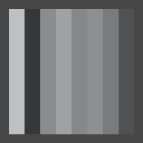
 Sharp vs. linear transitions in 1D at resolution 8.
This particular type of noise is known as Value noise.
Although the values of our noise are now interpolated, there are still sharp transitions. This is because we now see adjacent linear gradients that abruptly change direction. Instead of directly using the linear distance, we can turn it into a smooth curve by using a function that has a first derivative which is zero at both ends. That way the rate of change is always zero at gradient boundaries. Actually, let's go a step further and use a function with a second derivate that has the same properties. Such a function is 6t5 - 15t4 + 10t3.
Let's add a method that puts t though this function. Because we don't have an atomic power operation, we program it using multiplications only, for example as t t t (t (t 6 - 15) + 10).
- Why a 5th degree polynomial?
	private static float Smooth (float t) {
		return t * t * t * (t * (t * 6f - 15f) + 10f);
	}
Now we can smooth t before using it to interpolate between our hashes.
		t = Smooth(t);
		return Mathf.Lerp(h0, h1, t) * (1f / hashMask);

 Smooth transitions in 1D at resolution 8, 16, and 32.
The 1D noise only needed to interpolate along the x axis, but the 2D version also needs to interpolate along the y axis, performing a bilinear interpolation between four hashes. First, let's rewrite Value2D a bit so it has the same structure as the 1D version.
	public static float Value2D (Vector3 point, float frequency) {
		point *= frequency;
		int ix0 = Mathf.FloorToInt(point.x);
		int iy0 = Mathf.FloorToInt(point.y);
		ix0 &= hashMask;
		iy0 &= hashMask;

		int h0 = hash[ix0];
		int h00 = hash[h0 + iy0];

		return h00 * (1f / hashMask);
	}
Then add the hash of the opposite corner.
	public static float Value2D (Vector3 point, float frequency) {
		point *= frequency;
		int ix0 = Mathf.FloorToInt(point.x);
		int iy0 = Mathf.FloorToInt(point.y);
		ix0 &= hashMask;
		iy0 &= hashMask;
		int ix1 = ix0 + 1;
		int iy1 = iy0 + 1;

		int h0 = hash[ix0];
		int h1 = hash[ix1];
		int h00 = hash[h0 + iy0];
		int h11 = hash[h1 + iy1];

		return h00 * (1f / hashMask);
	}
But of course we need four hashes, not only the bottom left and top right ones.
		int h0 = hash[ix0];
		int h1 = hash[ix1];
		int h00 = hash[h0 + iy0];
		int h10 = hash[h1 + iy0];
		int h01 = hash[h0 + iy1];
		int h11 = hash[h1 + iy1];
And finally, we create the interpolants and perform the bilinear interpolation.
		int ix0 = Mathf.FloorToInt(point.x);
		int iy0 = Mathf.FloorToInt(point.y);
		float tx = point.x - ix0;
		float ty = point.y - iy0;
		ix0 &= hashMask;
		iy0 &= hashMask;
		int ix1 = ix0 + 1;
		int iy1 = iy0 + 1;

		int h0 = hash[ix0];
		int h1 = hash[ix1];
		int h00 = hash[h0 + iy0];
		int h10 = hash[h1 + iy0];
		int h01 = hash[h0 + iy1];
		int h11 = hash[h1 + iy1];

		tx = Smooth(tx);
		ty = Smooth(ty);
		return Mathf.Lerp(
			Mathf.Lerp(h00, h10, tx),
			Mathf.Lerp(h01, h11, tx),
			ty) * (1f / hashMask);
	}
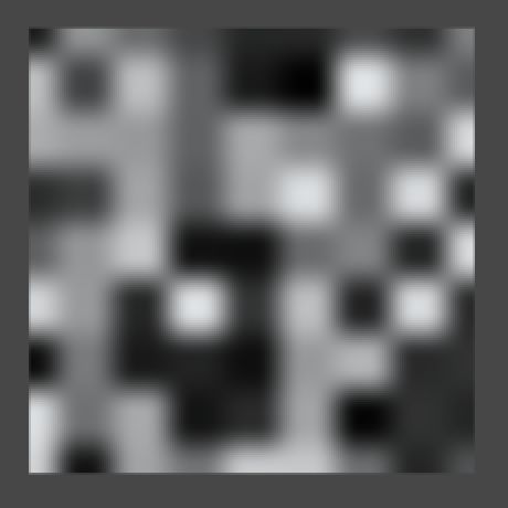
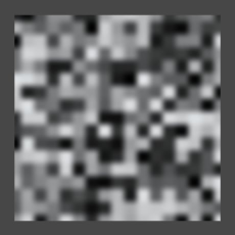
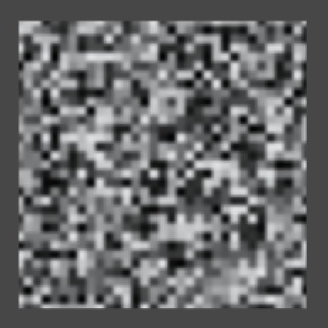 2D Value noise at resolution 8, 16, and 32.
When applying this approach to three dimensions the process is the same, it just gets bigger. you end up with eight hashes and need to perform a trilinear interpolation. I've copied the 2D code into the 3D method and marked the changes from there.
	public static float Value3D (Vector3 point, float frequency) {
		point *= frequency;
		int ix0 = Mathf.FloorToInt(point.x);
		int iy0 = Mathf.FloorToInt(point.y);
		int iz0 = Mathf.FloorToInt(point.z);
		float tx = point.x - ix0;
		float ty = point.y - iy0;
		float tz = point.z - iz0;
		ix0 &= hashMask;
		iy0 &= hashMask;
		iz0 &= hashMask;
		int ix1 = ix0 + 1;
		int iy1 = iy0 + 1;
		int iz1 = iz0 + 1;

		int h0 = hash[ix0];
		int h1 = hash[ix1];
		int h00 = hash[h0 + iy0];
		int h10 = hash[h1 + iy0];
		int h01 = hash[h0 + iy1];
		int h11 = hash[h1 + iy1];
		int h000 = hash[h00 + iz0];
		int h100 = hash[h10 + iz0];
		int h010 = hash[h01 + iz0];
		int h110 = hash[h11 + iz0];
		int h001 = hash[h00 + iz1];
		int h101 = hash[h10 + iz1];
		int h011 = hash[h01 + iz1];
		int h111 = hash[h11 + iz1];

		tx = Smooth(tx);
		ty = Smooth(ty);
		tz = Smooth(tz);
		return Mathf.Lerp(
			Mathf.Lerp(Mathf.Lerp(h000, h100, tx), Mathf.Lerp(h010, h110, tx), ty),
			Mathf.Lerp(Mathf.Lerp(h001, h101, tx), Mathf.Lerp(h011, h111, tx), ty),
			tz) * (1f / hashMask);
	}
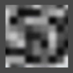
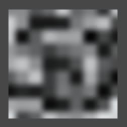
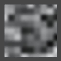
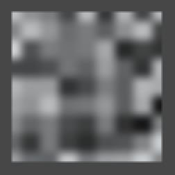
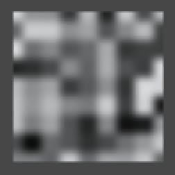 3D Value noise, moving to the next z coordinate in the lattice grid.
The 3D noise still appears the same as 2D noise when looking along the z axis. But now it smoothly morphs into a new pattern when moving along z, instead of abruptly changing. Because the rate of change is zero at the lattice points, when moving at constant speed the noise appears to pulse, oscillating between pure 2D patterns and fuzzy blends. Of course the picture changes dramatically when you rotate the quad.

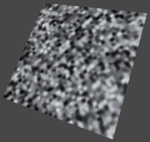 1D, 2D, and 3D Value noise with rotation (45,45,0).
Creating Gradient Noise
While Value noise is smooth, it has a blocky appearance. The patterns look random but are clearly constrained to a grid, which is undesirable when trying to create a more chaotic or natural-looking surface.
Until now we've selected a single fixed value per lattice coordinate, which means only the intensity of the image varies. If we could somehow add more variety – especially a sense of direction – we might be able to obfuscate that we're using a grid.
A solution is to associate gradients with each lattice coordinate, instead of constant values. If we orient those gradients in different directions and then interpolate between them, then the grid becomes a lot less obvious. As Ken Perlin was the first to use this technique, it is known as Perlin noise.
So let's create some Perlin noise! Begin by copying the three Value methods in Noise, renaming them to Perlin. Then also add a perlinMethods array. Let's go one step further and create an array of noise method arrays as well, containing our two existing arrays.
	public static NoiseMethod[] perlinMethods = {
		Perlin1D,
		Perlin2D,
		Perlin3D
	};

	public static NoiseMethod[][] noiseMethods = {
		valueMethods,
		perlinMethods
	};

	public static float Perlin1D (Vector3 point, float frequency) {
		…
	}

	public static float Perlin2D (Vector3 point, float frequency) {
		…
	}

	public static float Perlin3D (Vector3 point, float frequency) {
		…
	}
Then add a noise method type enumeration, which can be used to index the double array.
using UnityEngine;

public delegate float NoiseMethod (Vector3 point, float frequency);

public enum NoiseMethodType {
	Value,
	Perlin
}

public static class Noise {
	…
}
Now we can add another configuration option to TextureCreator, so we can use the inspector to switch between Value noise and Perlin noise.
	public NoiseMethodType type;

	public void FillTexture () {
		if (texture.width != resolution) {
			texture.Resize(resolution, resolution);
		}

		Vector3 point00 = transform.TransformPoint(new Vector3(-0.5f,-0.5f));
		Vector3 point10 = transform.TransformPoint(new Vector3( 0.5f,-0.5f));
		Vector3 point01 = transform.TransformPoint(new Vector3(-0.5f, 0.5f));
		Vector3 point11 = transform.TransformPoint(new Vector3( 0.5f, 0.5f));

		NoiseMethod method = Noise.noiseMethods[(int)type][dimensions - 1];
		float stepSize = 1f / resolution;
		for (int y = 0; y < resolution; y++) {
			Vector3 point0 = Vector3.Lerp(point00, point01, (y + 0.5f) * stepSize);
			Vector3 point1 = Vector3.Lerp(point10, point11, (y + 0.5f) * stepSize);
			for (int x = 0; x < resolution; x++) {
				Vector3 point = Vector3.Lerp(point0, point1, (x + 0.5f) * stepSize);
				texture.SetPixel(x, y, Color.white * method(point, frequency));
			}
		}
		texture.Apply();
	}
Selecing which noise type to use.
Of course we see no change yet when switching to Perlin noise, because those methods are still producing Value noise. So how how do we convert from using hash values to using hash gradients? Let's consider one-dimensional noise first, which so far is simply interpolating between two hash values.
The most basic one-dimensional gradient function is g(x) = x, which is simply x unmodified. In our case, we are only interested in the values of x in between two integer coodinates, so we can use our t variable, before it is smoothed. Let's visualize this gradient by simply returning t, ignoring the hashes for a moment.
	public static float Perlin1D (Vector3 point, float frequency) {
		point *= frequency;
		int i0 = Mathf.FloorToInt(point.x);
		float t = point.x - i0;
		i0 &= hashMask;
		int i1 = i0 + 1;

		int h0 = hash[i0];
		int h1 = hash[i1];

		return t;
	}
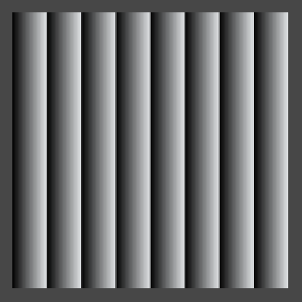 The most basic gradient.
Now every stripe has the same gradient, except that they are offset from one another. So for every t0, the gradient to the right of it is t1 = t0 - 1. Let's smoothly interpolate them.
		point *= frequency;
		int i0 = Mathf.FloorToInt(point.x);
		float t0 = point.x - i0;
		float t1 = t0 - 1f;
		i0 &= hashMask;
		int i1 = i0 + 1;

		int h0 = hash[i0];
		int h1 = hash[i1];

		float t = Smooth(t0);
		return Mathf.Lerp(t0, t1, t);
 Smoothly interpolating gradients.
The resulting image is dark because the gradients cancel each other out. Had we used linear interpolation it would be completely black, but because we're using smooth interpolation each gradient gets more dominant as it approaches zero. As the t1 values go below zero, we don't see them.
Indeed, Perlin noise can procude both positive and negative values. Ideally, its range is -1–1. To make this range visible, TextureCreator.FillTexture has to scale and offset the noise samples so -1 becomes 0, 0 becomes 0.5, and 1 stays 1, but we shouldn't do this when using Value noise.
		for (int y = 0; y < resolution; y++) {
			Vector3 point0 = Vector3.Lerp(point00, point01, (y + 0.5f) * stepSize);
			Vector3 point1 = Vector3.Lerp(point10, point11, (y + 0.5f) * stepSize);
			for (int x = 0; x < resolution; x++) {
				Vector3 point = Vector3.Lerp(point0, point1, (x + 0.5f) * stepSize);
				float sample = method(point, frequency);
				if (type != NoiseMethodType.Value) {
					sample = sample * 0.5f + 0.5f;
				}
				texture.SetPixel(x, y, Color.white * sample);
			}
		}
 Mapping -1–1 to 0–1.
To reintroduce randomness, we have to convert the hash values into gradient functions. Assuming we have an array of 1D gradients, we can simply use the hash values to index this array, applying a mask so the arrays don't need to be the same length.
	public static float Perlin1D (Vector3 point, float frequency) {
		point *= frequency;
		int i0 = Mathf.FloorToInt(point.x);
		float t0 = point.x - i0;
		float t1 = t0 - 1f;
		i0 &= hashMask;
		int i1 = i0 + 1;

		float g0 = gradients1D[hash[i0] & gradientsMask1D];
		float g1 = gradients1D[hash[i1] & gradientsMask1D];

		float t = Smooth(t0);
		return Mathf.Lerp(t0, t1, t);
	}
For gradients, we simply pick the two directions of movement possible in one dimension. This means we end up using positive gradients for even hash values, and negative gradients for odd hash values.
	private static float[] gradients1D = {
		1f, -1f
	};

	private const int gradientsMask1D = 1;
After retrieving these gradients, we compute their values at the current point by multiplying with t0 and t1, which can then be interpolated.
		float g0 = gradients1D[hash[i0] & gradientsMask1D];
		float g1 = gradients1D[hash[i1] & gradientsMask1D];

		float v0 = g0 * t0;
		float v1 = g1 * t1;

		float t = Smooth(t0);
		return Mathf.Lerp(v0, v1, t);
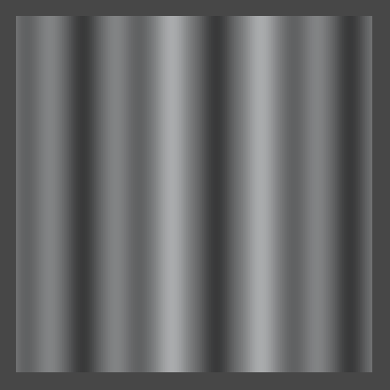 Mixing two different gradients.
Now adjacent gradients can point in either the same or opposite directions, going either up or down. So there are four possible transitions, and the order in which they appear depends on the hash values.
While this is already 1D Perlin noise, it doesn't yet cover the entire -1–1 range, so we need to normalize it. So what is currently the maximum possible value? If we were to linearly interpolate two gradients pointing in opposite directions, they would both be 0.5 at the halfway point, which means their interpolation is also 0.5 there. As the gradients start at zero, this must be the maximum possible value. Smoothly interpolating does not change this maximum. So doubling the result will produde the desired range.
return Mathf.Lerp(v0, v1, t) * 2f;
 Normalized 1D Perlin noise at resolution 8, 16, and 32.
For 2D Perlin noise we have to perform the same steps, but now in two dimensions. First, we need 2D gradient coefficients, so we need to use Vector2 structs instead of floats. The most obvious gradient choices are right, left, up, and down, so let's pick those.
	private static Vector2[] gradients2D = {
		new Vector2( 1f, 0f),
		new Vector2(-1f, 0f),
		new Vector2( 0f, 1f),
		new Vector2( 0f,-1f),
	};

	private const int gradientsMask2D = 3;
This time we're using gradient functions of the form g(x, y) = ax + by, where a and b are either -1, 0, or 1. Let's add a convenient method to compute this function for us, given a gradient vector.
- Why name it Dot?
	private static float Dot (Vector2 g, float x, float y) {
		return g.x * x + g.y * y;
	}
Next, we can compute gradients values just like we did for 1D Perlin noise.
	public static float Perlin2D (Vector3 point, float frequency) {
		point *= frequency;
		int ix0 = Mathf.FloorToInt(point.x);
		int iy0 = Mathf.FloorToInt(point.y);
		float tx0 = point.x - ix0;
		float ty0 = point.y - iy0;
		float tx1 = tx0 - 1f;
		float ty1 = ty0 - 1f;
		ix0 &= hashMask;
		iy0 &= hashMask;
		int ix1 = ix0 + 1;
		int iy1 = iy0 + 1;

		int h0 = hash[ix0];
		int h1 = hash[ix1];
		Vector2 g00 = gradients2D[hash[h0 + iy0] & gradientsMask2D];
		Vector2 g10 = gradients2D[hash[h1 + iy0] & gradientsMask2D];
		Vector2 g01 = gradients2D[hash[h0 + iy1] & gradientsMask2D];
		Vector2 g11 = gradients2D[hash[h1 + iy1] & gradientsMask2D];

		float v00 = Dot(g00, tx0, ty0);
		float v10 = Dot(g10, tx1, ty0);
		float v01 = Dot(g01, tx0, ty1);
		float v11 = Dot(g11, tx1, ty1);

		float tx = Smooth(tx0);
		float ty = Smooth(ty0);
		return Mathf.Lerp(
			Mathf.Lerp(v00, v10, tx),
			Mathf.Lerp(v01, v11, tx),
			ty) * 2f;
	}
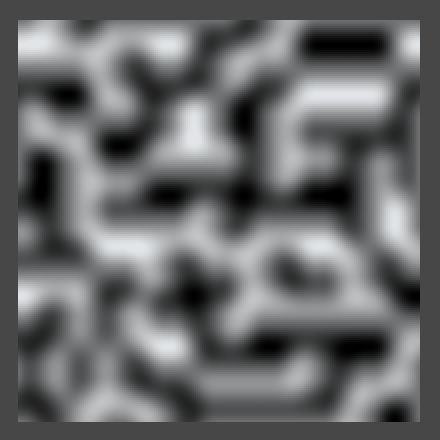
 Interpolating four gradients vs. showing only v00.
This is starting to look interesting, but the noise has a dominant horizontal and vertical alignment. What would happen if we made our gradients diagonal instead?
	private static Vector2[] gradients2D = {
		new Vector2( 1f, 1f),
		new Vector2(-1f, 1f),
		new Vector2( 1f,-1f),
		new Vector2(-1f,-1f)
	};
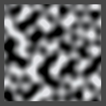
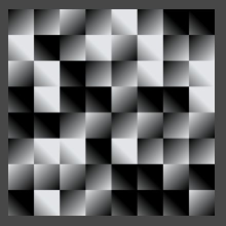 Diagonal gradients that go out of range, interpolated vs. only v00.
As you probably expected, we're now seeing a strong diagonal alignment. We also see that the noise goes out of range. That happens because when the four corner gradients of a lattice cell all end up pointing towards its center, the final interpolated value in the middle will be 1. So we shouldn't double our result when using these gradients.
While using either axis-aligned gradients or diagonal gradients doesn't look varied enough, using both at the same time will give us a lot more to work with. But then we better make sure that all gradient vectors have the same length, otherwise their intensity will vary a lot. We can do that by normalizing the diagonals.
	private static Vector2[] gradients2D = {
		new Vector2( 1f, 0f),
		new Vector2(-1f, 0f),
		new Vector2( 0f, 1f),
		new Vector2( 0f,-1f),
		new Vector2( 1f, 1f).normalized,
		new Vector2(-1f, 1f).normalized,
		new Vector2( 1f,-1f).normalized,
		new Vector2(-1f,-1f).normalized
	};

	private const int gradientsMask2D = 7;
In this case the maximum value is still reached at the center off a cell with four diagonal gradients pointing at its center, however that value is no longer 1 but √½. So we need to divide by √½, which is the same as multiplying by √2.
- Why is it √½?
		return Mathf.Lerp(
			Mathf.Lerp(v00, v10, tx),
			Mathf.Lerp(v01, v11, tx),
			ty) * sqr2;
Unfortunately the square root of 2 is not a rational number, so we cannot write it as a constant. We could write an approximation, like 1.4142136, but let's just use a static variable and have Mathf.Sqrt figure it out.
private static float sqr2 = Mathf.Sqrt(2f);
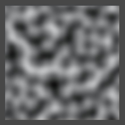

 Normalized 2D Perlin noise at resolution 8, 16, and 32.
We can still see horizontal and diagonal structures, but the probability of either showing up is equal. But what if we included even more gradients, like using sixteen rotated in 22.5 degree increments? It turns out that this doesn't really increase the apparent randomness of the patterns, so we stick with eight.
The same is true for three dimensions. Ken Perlin found that you don't need many gradients. He chose just twelve vectors for his improved noise, each pointing from the center of a cube to the middle of one of its edges. However, twelve is not a power of two, so bit masking doesn't work with that. He decided to lengthen his array by including four vectors twice. He picked four that form a regular tetrahedron so they don't introduce a directional bias. Let us use the same gradients.
	private static Vector3[] gradients3D = {
		new Vector3( 1f, 1f, 0f),
		new Vector3(-1f, 1f, 0f),
		new Vector3( 1f,-1f, 0f),
		new Vector3(-1f,-1f, 0f),
		new Vector3( 1f, 0f, 1f),
		new Vector3(-1f, 0f, 1f),
		new Vector3( 1f, 0f,-1f),
		new Vector3(-1f, 0f,-1f),
		new Vector3( 0f, 1f, 1f),
		new Vector3( 0f,-1f, 1f),
		new Vector3( 0f, 1f,-1f),
		new Vector3( 0f,-1f,-1f),

		new Vector3( 1f, 1f, 0f),
		new Vector3(-1f, 1f, 0f),
		new Vector3( 0f,-1f, 1f),
		new Vector3( 0f,-1f,-1f)
	};

	private const int gradientsMask3D = 15;
While we could normalize these gradients, as they all have the same length this is not really necessary. Furthermore, Because each individual vector only uses two dimensions, the maximum possible value is the same as for the unnormalized 2D diagonals case, which is 1. So we don't have to scale the interpolated value at all.
The only extra thing we need to do is add another Dot method that works for three dimensions.
	private static float Dot (Vector3 g, float x, float y, float z) {
		return g.x * x + g.y * y + g.z * z;
	}

	public static float Perlin3D (Vector3 point, float frequency) {
		point *= frequency;
		int ix0 = Mathf.FloorToInt(point.x);
		int iy0 = Mathf.FloorToInt(point.y);
		int iz0 = Mathf.FloorToInt(point.z);
		float tx0 = point.x - ix0;
		float ty0 = point.y - iy0;
		float tz0 = point.z - iz0;
		float tx1 = tx0 - 1f;
		float ty1 = ty0 - 1f;
		float tz1 = tz0 - 1f;
		ix0 &= hashMask;
		iy0 &= hashMask;
		iz0 &= hashMask;
		int ix1 = ix0 + 1;
		int iy1 = iy0 + 1;
		int iz1 = iz0 + 1;

		int h0 = hash[ix0];
		int h1 = hash[ix1];
		int h00 = hash[h0 + iy0];
		int h10 = hash[h1 + iy0];
		int h01 = hash[h0 + iy1];
		int h11 = hash[h1 + iy1];
		Vector3 g000 = gradients3D[hash[h00 + iz0] & gradientsMask3D];
		Vector3 g100 = gradients3D[hash[h10 + iz0] & gradientsMask3D];
		Vector3 g010 = gradients3D[hash[h01 + iz0] & gradientsMask3D];
		Vector3 g110 = gradients3D[hash[h11 + iz0] & gradientsMask3D];
		Vector3 g001 = gradients3D[hash[h00 + iz1] & gradientsMask3D];
		Vector3 g101 = gradients3D[hash[h10 + iz1] & gradientsMask3D];
		Vector3 g011 = gradients3D[hash[h01 + iz1] & gradientsMask3D];
		Vector3 g111 = gradients3D[hash[h11 + iz1] & gradientsMask3D];

		float v000 = Dot(g000, tx0, ty0, tz0);
		float v100 = Dot(g100, tx1, ty0, tz0);
		float v010 = Dot(g010, tx0, ty1, tz0);
		float v110 = Dot(g110, tx1, ty1, tz0);
		float v001 = Dot(g001, tx0, ty0, tz1);
		float v101 = Dot(g101, tx1, ty0, tz1);
		float v011 = Dot(g011, tx0, ty1, tz1);
		float v111 = Dot(g111, tx1, ty1, tz1);

		float tx = Smooth(tx0);
		float ty = Smooth(ty0);
		float tz = Smooth(tz0);
		return Mathf.Lerp(
			Mathf.Lerp(Mathf.Lerp(v000, v100, tx), Mathf.Lerp(v010, v110, tx), ty),
			Mathf.Lerp(Mathf.Lerp(v001, v101, tx), Mathf.Lerp(v011, v111, tx), ty),
			tz);
	}

 3D Perlin noise at resolution 8, 16, and 32.
Because we are using different gradients for 3D than for 2D, the two noise patterns appear slightly different when viewed along the z axis. While the 3D gradients are all the same length when taking all their dimensions into account, when you ignore one dimension this is no longer true.


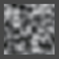
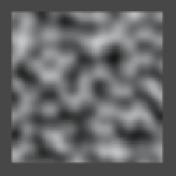
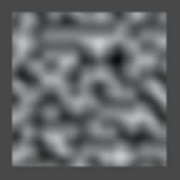 3D Perlin noise, moving to the next z coordinate in the lattice grid.
Of course 3D Perlin noise makes the most sense when animating 2D patterns or when really working with three dimensions.
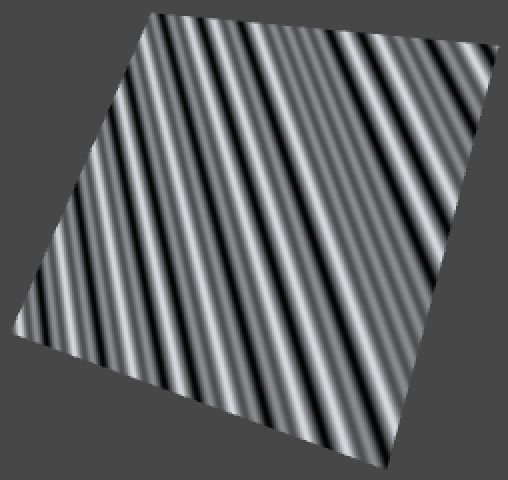
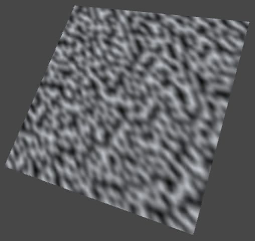 1D, 2D, and 3D Perlin noise with rotation (45,45,0).
Making Fractal Noise
Because our noise is based on a lattice, its features – though seemingly random – are all the same size. However, many things have both larger and smaller features. Think clouds, mountains, coastlines, and many plants. As you zoom in, you will discover more and more detail. Often, the details look similar to the larger shape, like a branch on a tree is could look like a smaller tree itself, with even smaller braches. These self-similar shapes are known as fractals.
Our noise patterns don't have this property, but we can make a limited version of it by combining samples at different frequencies. For example, adding frequency 8 and frequency 16 together. Here the frequency 16 samples represent the details, so they should be less pronounced than the larger features. Because the frequency is doubled, it makes sense to half its strength. Of couse we can go a step further, and also add a frequency 32 sample at quarter strength, and so on. Such a summation of noise frequencies is known as 1/f noise, or fractal noise, or fractional noise, pink noise, and some other names.
Let's add a Sum method to Noise that combines two samples, the second at double frequency and half strength or amplitude. We can give it a parameter to determine which method to use, so we don't need to create a separate summation method for all our noise types and dimensions.
	public static float Sum (NoiseMethod method, Vector3 point, float frequency) {
		return method(point, frequency) + method(point * 2f, frequency * 2f) * 0.5f;
	}
Now TextureCreator.FillTexture can pass its noise method to Sum instead of calling it directly.
				Vector3 point = Vector3.Lerp(point0, point1, (x + 0.5f) * stepSize);
				float sample = Noise.Sum(method, point, frequency);
				if (type != NoiseMethodType.Value) {
					sample = sample * 0.5f + 0.5f;
				}
				texture.SetPixel(x, y, Color.white * sample);
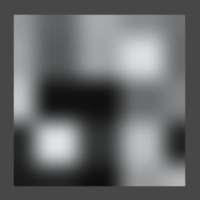
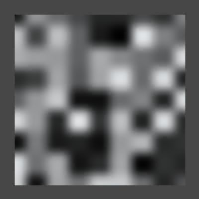 2D Value noise at resolution 4 and 8, separate and summed with 8 at half strength.
Of course the range of this summation is 0–1.5, or -1.5–1.5 when using Perlin noise, so to get a normalized result we have to divide by 1.5.
return ((method(point, frequency) + method(point * 2f, frequency * 2f) * 0.5f) / 1.5f;

 Normalized sum, for Value and Perlin noise.
Of course we don't always want to sum exactly two samples, so let's make configurable how many samples, or octaves, we want to include. Because each successive octave will be smaller than the previous, at some point adding more octaves won't visibly change the image any more. Besides that, more samples require more computation time, so this also limits how many octaves are practical.
Let's add an octaves setting to TextureCreator and give it a range from one to eight.
	public float frequency = 1f;

	[Range(1, 8)]
	public int octaves = 1;

	[Range(1, 3)]
	public int dimensions = 3;
Then pass it to Sum in FillTexture.
float sample = Noise.Sum(method, point, frequency, octaves);
Noise.Sum now has to accumulate all the octaves, at each step increasing the frequency, halving the amplitude, and keeping track of the total range for nomalization. Because it is pointless to ask for zero octaves, let's always compute the first, then loop through the others.
	public static float Sum (NoiseMethod method, Vector3 point, float frequency, int octaves) {
		float sum = method(point, frequency);
		float amplitude = 1f;
		float range = 1f;
		for (int o = 1; o < octaves; o++) {
			frequency *= 2f;
			amplitude *= 0.5f;
			range += amplitude;
			sum += method(point, frequency) * amplitude;
		}
		return sum / range;
	}


 Value and Perlin noise with base frequency 3, from one to five octaves.
It is not required that the frequency is exactly doubled each octave, neither does the amplitude need to be exactly halved. The factor by which the frequency changes is often known as the lacunarity, while the amplitude factor is often named persistence or gain. Let's add these options to TextureCreator with reasonable ranges.
	public float frequency = 1f;

	[Range(1, 8)]
	public int octaves = 1;

	[Range(1f, 4f)]
	public float lacunarity = 2f;

	[Range(0f, 1f)]
	public float persistence = 0.5f;
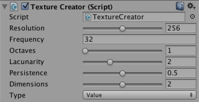 Lacunarity and persistence with typical values.
Of course we need to pass them to the Sum method.
float sample = Noise.Sum(method, point, frequency, octaves, lacunarity, persistence);
And Sum itself has to use them instead of contant values.
	public static float Sum (
		NoiseMethod method, Vector3 point, float frequency, int octaves, float lacunarity, float persistence
	) {
		float sum = method(point, frequency);
		float amplitude = 1f;
		float range = 1f;
		for (int o = 1; o < octaves; o++) {
			frequency *= lacunarity;
			amplitude *= persistence;
			range += amplitude;
			sum += method(point, frequency) * amplitude;
		}
		return sum / range;
	}
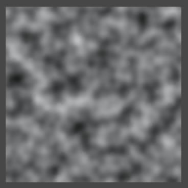
 Two octaves of Perlin noise with base frequency 8, using lacunarity 2, 3, and 4.


 Three octaves of Perlin noise with base frequency 8, using persistence ½, ¾, and 1.
You might have noticed that when changing the frequency or the lacunarity, it looks like you're zooming from the center of the image. This happens when the quad is placed at the origin. Because everything is relative to that point, the same features of successive octaves will overlap, producing lines or cones that are obviously not random. This is a problem in all dimensions. To avoid these artifacts, move away from the origin.
 Rotated summed 3D Value noise, positioned at (0,0,0) and at (1,2,3).
So far we've converted the noise values to grayscale colors, but we need not limit ourselves to that. To allow more interesting color transitions, let's wrap up TextureCreator by adding a gradient to it.
public Gradient coloring;
If you let the gradient go from black to white, you'll get the same result as before. So design something else instead. As an example, I put a narrow black region in the middle, made the lower half white–blue, and the upper half yellow–red. This will divide the patterns into two parts.
To actually show the colors, instead of multiplying our noise samples with a constant white color, we use them to evaluate the gradient in FillTexture.
texture.SetPixel(x, y, coloring.Evaluate(sample));
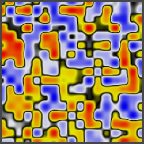
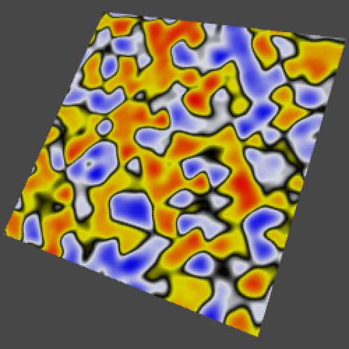
 Colored 2D and 3D Value noise, one octave with frequency 16, and six octaves with base frequency 3.
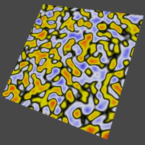

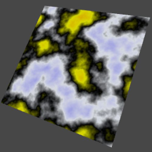 Colored 2D and 3D Perlin noise, one octave with frequency 16, and six octaves with base frequency 3.
Of course you can create many different results with other gradients, especially once you start playing with lacunarity and persistence as well. Have fun experimenting with noise settings, or immediately move on to Noise Derivatives.