Python计算机视觉编程(六)增强现实
增强现实
- 静态
- 在图像中投影并描绘3D模型
- 相机投影模型
- 针孔相机模型
- 内参数
- 外参数
- 相机标定原理——张正友标定
- 相机标定解决办法
- 封闭解
- 最大似然估计
- 径向畸变的处理
- 标定结果
- 从OpenCV到OpenGL
- 代码
- 动态
- 代码实现
静态
增强现实技术(Augmented Reality,简称 AR),是一种实时地计算摄影机影像的位置及角度并加上相应图像、视频、3D模型的技术,这种技术的目标是在屏幕上把虚拟世界套在现实世界并进行互动。

我们可以把过程大致分为以下四步:
- 识别参考平面
- 特征提取
- 特征描述
- 特征匹配
- 计算单应性矩阵
- 转换坐标系
- 在图像中投影并描绘3D模型
在图像中投影并描绘3D模型
前三个部分在之前的博客都有提及
python计算机视觉编程(三)——Harris角点 SIFT 匹配地理标记图像.
python计算机视觉编程(四)图像到图像的映射.
所以主要讲述一下第四点
相机投影模型
相机成像的过程实际是将三维空间中的点映射到二维空间的过程,可以简单的使用小孔成像模型来描述该过程。
针孔相机模型
- 相机坐标系(三维坐标系)
相机的中心被称为光心,以光心c为原点和坐标轴X,Y,Z组成了相机坐标系 - 图像坐标系(二维坐标系)
成像平面中,以成像平面的中心像主点为原点和坐标轴x,y组成了图像坐标系。

根据图片中的三角形相似可以得到两个坐标系的对应关系

但是该映射z却不是线性的,引入新坐标线性化,得到
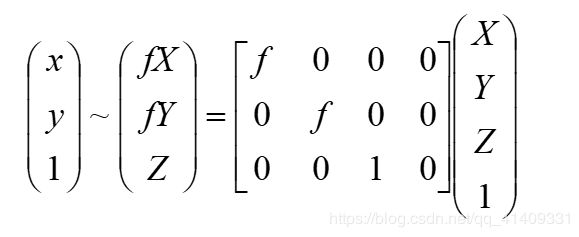
内参数
相机的内参数由下面的两部分组成:
- 射影变换本身的参数,相机的焦点到成像平面的距离,也就是焦距f。
- 从成像平面坐标系到像素坐标系的变换。上面推导中使用的像点坐标p=(x,y)是成像平面坐标系下,以成像平面的中心为原点。而实际像素点的表示方法是以像素来描述,坐标原点通常是图像的左上角,X轴沿着水平方向向左,Y轴竖直向下。像素是一个矩形块,所以像素坐标和成像平面坐标之间,相差了一个缩放和原点的平移。
假设像素坐标的水平方向的轴为x,竖直方向的轴为y,那么将一个成像平面的坐标(x,y)在水平方向上缩放a倍,在竖直方向上缩放b倍,同时平移(cx,cy),就可以得到像素坐标系的坐标(x’,y’),其公式如下: - x=a*x’+cx
- y=b*x’+cy
与上面得到的其次坐标联立,有

我们就能得到相机的内参矩阵
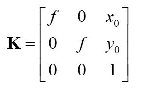
外参数
我们知道p=KP,其中p是图像坐标系的点,K是内参矩阵,P是相机坐标系。
而相机坐标系并不稳定,会变化,我们引进一个不变的世界坐标系。
设P’是相机坐标系的点,P是世界坐标系,R是旋转矩阵,t是一个平移向量,那么有P’=RP+t

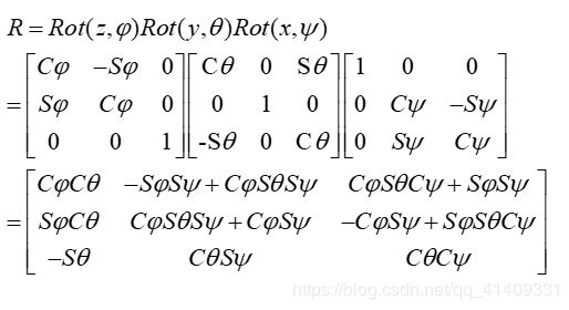
将其写成齐次坐标的形式,我们可以得到 外参数T
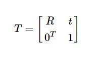
最后我们得到

相机标定原理——张正友标定
张正友标定只考虑了径向畸变,没有考虑切向畸变


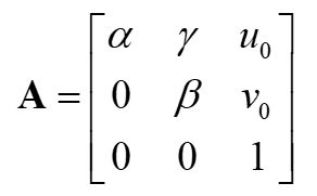
我们把世界坐标系放在平面上,即z=0,可以得到:

那么,关系可以改写为


λ 是任意标量。可知r1和r2是正交的,有:

相机标定解决办法
封闭解
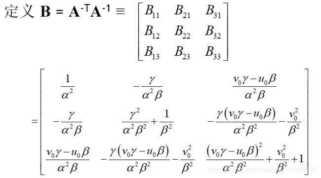
B是对称的,定义一个六维向量

设h中第j行为

我们得到

其中vij为

写成其次形式
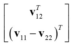
对n张图片有

式中v是一个2n*6的矩阵

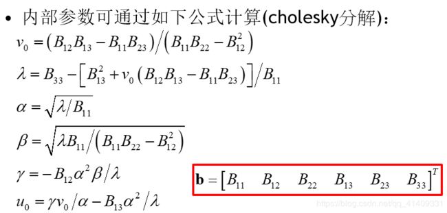
b被估计出来以后,我们可以计算内参矩阵A,之后外部参数也能算出来。

最大似然估计
上面的解决办法,在一般情况下是没有物理意义的。
我们给定n张图片,每张m个角点。最大似然可以从下列公式的最小值得到

径向畸变的处理

径向畸变一般很小,简单的忽略径向畸变后,可以用最大似然估计的方法估计另外五个参数。一种策略是估计其他参数后在估计k1和k2。然后从上式中,对每幅图的每个点可以得到两个方程

n幅图像中共有m个点,迭代所有方程得到一个2mn的方程组,或者以矩阵形式![]()
其中![]()
由最小二乘法得到

k1和k2估计出来后,可以通过解最大似然估计来重新估计其他参数。

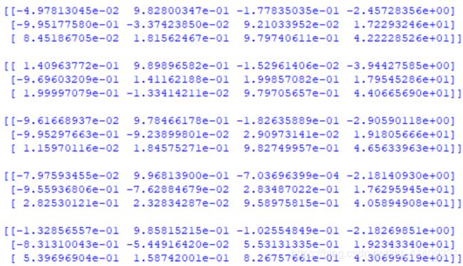
标定结果
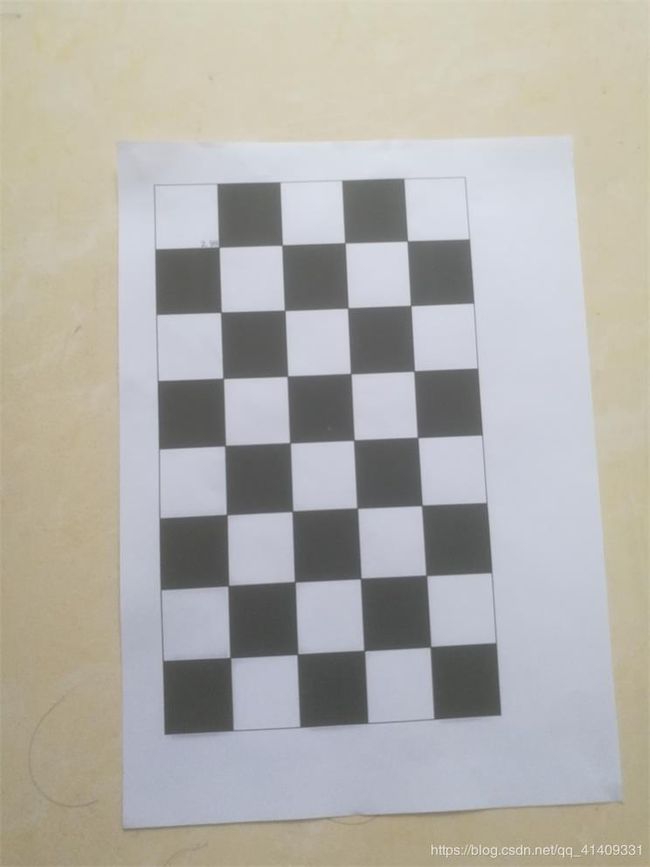
拍摄设备:荣耀V8
棋盘如下,共拍摄15张照片
内参矩阵

k1 k2
![]()
外参矩阵


从OpenCV到OpenGL
了解了上面的内容,得到摄像机的内参K和外参[R|T]后,就可以开始考虑将虚拟物体添加进来了。
代码
结果如开头图片
import math
import pickle
from pylab import *
from OpenGL.GL import *
from OpenGL.GLU import *
from OpenGL.GLUT import *
import pygame, pygame.image
from pygame.locals import *
from PCV.geometry import homography, camera
from PCV.localdescriptors import sift

def cube_points(c, wid):
    """ Creates a list of points for plotting
        a cube with plot. (the first 5 points are
        the bottom square, some sides repeated). """
    p = []
    # bottom
    p.append([c[0]-wid, c[1]-wid, c[2]-wid])
    p.append([c[0]-wid, c[1]+wid, c[2]-wid])
    p.append([c[0]+wid, c[1]+wid, c[2]-wid])
    p.append([c[0]+wid, c[1]-wid, c[2]-wid])
    p.append([c[0]-wid, c[1]-wid, c[2]-wid]) #same as first to close plot

    # top
    p.append([c[0]-wid, c[1]-wid, c[2]+wid])
    p.append([c[0]-wid, c[1]+wid, c[2]+wid])
    p.append([c[0]+wid, c[1]+wid, c[2]+wid])
    p.append([c[0]+wid, c[1]-wid, c[2]+wid])
    p.append([c[0]-wid, c[1]-wid, c[2]+wid]) #same as first to close plot

    # vertical sides
    p.append([c[0]-wid, c[1]-wid, c[2]+wid])
    p.append([c[0]-wid, c[1]+wid, c[2]+wid])
    p.append([c[0]-wid, c[1]+wid, c[2]-wid])
    p.append([c[0]+wid, c[1]+wid, c[2]-wid])
    p.append([c[0]+wid, c[1]+wid, c[2]+wid])
    p.append([c[0]+wid, c[1]-wid, c[2]+wid])
    p.append([c[0]+wid, c[1]-wid, c[2]-wid])

    return array(p).T

def my_calibration(sz):
    row, col = sz
    fx = 2555*col/2592
    fy = 2586*row/1936
    K = diag([fx, fy, 1])
    K[0, 2] = 0.5*col
    K[1, 2] = 0.5*row
    return K

def set_projection_from_camera(K):
	glMatrixMode(GL_PROJECTION)
	glLoadIdentity()
	fx = K[0,0]
	fy = K[1,1]
	fovy = 2*math.atan(0.5*height/fy)*180/math.pi
	aspect = (width*fy)/(height*fx)
	near = 0.1
	far = 100.0
	gluPerspective(fovy,aspect,near,far)
	glViewport(0,0,width,height)

def set_modelview_from_camera(Rt):
	glMatrixMode(GL_MODELVIEW)
	glLoadIdentity()
	Rx = np.array([[1,0,0],[0,0,-1],[0,1,0]])
	R = Rt[:,:3]
	U,S,V = np.linalg.svd(R)
	R = np.dot(U,V)
	R[0,:] = -R[0,:]
	t = Rt[:,3]
	M = np.eye(4)
	M[:3,:3] = np.dot(R,Rx)
	M[:3,3] = t
	M = M.T
	m = M.flatten()
	glLoadMatrixf(m)

def draw_background(imname):
	bg_image = pygame.image.load(imname).convert()
	bg_data = pygame.image.tostring(bg_image,"RGBX",1)
	glMatrixMode(GL_MODELVIEW)
	glLoadIdentity()

	glClear(GL_COLOR_BUFFER_BIT | GL_DEPTH_BUFFER_BIT)
	glEnable(GL_TEXTURE_2D)
	glBindTexture(GL_TEXTURE_2D,glGenTextures(1))
	glTexImage2D(GL_TEXTURE_2D,0,GL_RGBA,width,height,0,GL_RGBA,GL_UNSIGNED_BYTE,bg_data)
	glTexParameterf(GL_TEXTURE_2D,GL_TEXTURE_MAG_FILTER,GL_NEAREST)
	glTexParameterf(GL_TEXTURE_2D,GL_TEXTURE_MIN_FILTER,GL_NEAREST)
	glBegin(GL_QUADS)
	glTexCoord2f(0.0,0.0); glVertex3f(-1.0,-1.0,-1.0)
	glTexCoord2f(1.0,0.0); glVertex3f( 1.0,-1.0,-1.0)
	glTexCoord2f(1.0,1.0); glVertex3f( 1.0, 1.0,-1.0)
	glTexCoord2f(0.0,1.0); glVertex3f(-1.0, 1.0,-1.0)
	glEnd()
	glDeleteTextures(1)


def draw_teapot(size):
	glEnable(GL_LIGHTING)
	glEnable(GL_LIGHT0)
	glEnable(GL_DEPTH_TEST)
	glClear(GL_DEPTH_BUFFER_BIT)
	glMaterialfv(GL_FRONT,GL_AMBIENT,[0,0,0,0])
	glMaterialfv(GL_FRONT,GL_DIFFUSE,[0.5,0.0,0.0,0.0])
	glMaterialfv(GL_FRONT,GL_SPECULAR,[0.7,0.6,0.6,0.0])
	glMaterialf(GL_FRONT,GL_SHININESS,0.25*128.0)
	glutSolidTeapot(size)

width,height = 1000,747
def setup():
	pygame.init()
	pygame.display.set_mode((width,height),OPENGL | DOUBLEBUF)
	pygame.display.set_caption("OpenGL AR demo")

# compute features
sift.process_image('book_frontal.JPG', 'im0.sift')
l0, d0 = sift.read_features_from_file('im0.sift')

sift.process_image('book_perspective.JPG', 'im1.sift')
l1, d1 = sift.read_features_from_file('im1.sift')

# match features and estimate homography
matches = sift.match_twosided(d0, d1)
ndx = matches.nonzero()[0]
fp = homography.make_homog(l0[ndx, :2].T)
ndx2 = [int(matches[i]) for i in ndx]
tp = homography.make_homog(l1[ndx2, :2].T)

model = homography.RansacModel()
H, inliers = homography.H_from_ransac(fp, tp, model)

K = my_calibration((747, 1000))
cam1 = camera.Camera(hstack((K, dot(K, array([[0], [0], [-1]])))))
box = cube_points([0, 0, 0.1], 0.1)
box_cam1 = cam1.project(homography.make_homog(box[:, :5]))
box_trans = homography.normalize(dot(H,box_cam1))
cam2 = camera.Camera(dot(H, cam1.P))
A = dot(linalg.inv(K), cam2.P[:, :3])
A = array([A[:, 0], A[:, 1], cross(A[:, 0], A[:, 1])]).T
cam2.P[:, :3] = dot(K, A)

Rt=dot(linalg.inv(K),cam2.P)

setup()
draw_background("book_perspective.bmp")
set_projection_from_camera(K)
set_modelview_from_camera(Rt)
draw_teapot(0.05)

pygame.display.flip()
while True:
	for event in pygame.event.get():
		if event.type==pygame.QUIT:
			sys.exit()
动态
动态的增强现实相比静态需要对摄像头获取的图像进行实时处理,再在其上描绘3D模型,由于sift速度慢,使用效果可能不是很好,这里使用ORB(其他特征提取也行),整体流程与静态基本没差。参考了其他博主。https://bitesofcode.wordpress.com/2017/09/12/augmented-reality-with-python-and-opencv-part-1/
代码实现
import argparse

import cv2
import numpy as np
import math
import os
from objloader_simple import *

# Minimum number of matches that have to be found
# to consider the recognition valid
MIN_MATCHES = 10


def main():
    """
    This functions loads the target surface image,
    """
    homography = None
    # matrix of camera parameters (made up but works quite well for me)
    camera_parameters = np.array([[800, 0, 320], [0, 800, 240], [0, 0, 1]])
    # create ORB keypoint detector
    orb = cv2.ORB_create()
    # create BFMatcher object based on hamming distance
    bf = cv2.BFMatcher(cv2.NORM_HAMMING, crossCheck=True)
    # load the reference surface that will be searched in the video stream
    dir_name = os.getcwd()
    model = cv2.imread(os.path.join(dir_name, 'reference/model.jpg'), 0)
    # Compute model keypoints and its descriptors
    kp_model, des_model = orb.detectAndCompute(model, None)
    # Load 3D model from OBJ file
    obj = OBJ(os.path.join(dir_name, 'models/fox.obj'), swapyz=True)
    # init video capture
    cap = cv2.VideoCapture(0)

    while True:
        # read the current frame
        ret, frame = cap.read()
        if not ret:
            print "Unable to capture video"
            return
        # find and draw the keypoints of the frame
        kp_frame, des_frame = orb.detectAndCompute(frame, None)
        # match frame descriptors with model descriptors
        matches = bf.match(des_model, des_frame)
        # sort them in the order of their distance
        # the lower the distance, the better the match
        matches = sorted(matches, key=lambda x: x.distance)

        # compute Homography if enough matches are found
        if len(matches) > MIN_MATCHES:
            # differenciate between source points and destination points
            src_pts = np.float32([kp_model[m.queryIdx].pt for m in matches]).reshape(-1, 1, 2)
            dst_pts = np.float32([kp_frame[m.trainIdx].pt for m in matches]).reshape(-1, 1, 2)
            # compute Homography
            homography, mask = cv2.findHomography(src_pts, dst_pts, cv2.RANSAC, 5.0)
            if args.rectangle:
                # Draw a rectangle that marks the found model in the frame
                h, w = model.shape
                pts = np.float32([[0, 0], [0, h - 1], [w - 1, h - 1], [w - 1, 0]]).reshape(-1, 1, 2)
                # project corners into frame
                dst = cv2.perspectiveTransform(pts, homography)
                # connect them with lines
                frame = cv2.polylines(frame, [np.int32(dst)], True, 255, 3, cv2.LINE_AA)
            # if a valid homography matrix was found render cube on model plane
            if homography is not None:
                try:
                    # obtain 3D projection matrix from homography matrix and camera parameters
                    projection = projection_matrix(camera_parameters, homography)
                    # project cube or model
                    frame = render(frame, obj, projection, model, False)
                    #frame = render(frame, model, projection)
                except:
                    pass
            # draw first 10 matches.
            if args.matches:
                frame = cv2.drawMatches(model, kp_model, frame, kp_frame, matches[:10], 0, flags=2)
            # show result
            cv2.imshow('frame', frame)
            if cv2.waitKey(1) & 0xFF == ord('q'):
                break

        else:
            print "Not enough matches found - %d/%d" % (len(matches), MIN_MATCHES)

    cap.release()
    cv2.destroyAllWindows()
    return 0

def render(img, obj, projection, model, color=False):
    """
    Render a loaded obj model into the current video frame
    """
    vertices = obj.vertices
    scale_matrix = np.eye(3) * 3
    h, w = model.shape

    for face in obj.faces:
        face_vertices = face[0]
        points = np.array([vertices[vertex - 1] for vertex in face_vertices])
        points = np.dot(points, scale_matrix)
        # render model in the middle of the reference surface. To do so,
        # model points must be displaced
        points = np.array([[p[0] + w / 2, p[1] + h / 2, p[2]] for p in points])
        dst = cv2.perspectiveTransform(points.reshape(-1, 1, 3), projection)
        imgpts = np.int32(dst)
        if color is False:
            cv2.fillConvexPoly(img, imgpts, (137, 27, 211))
        else:
            color = hex_to_rgb(face[-1])
            color = color[::-1]  # reverse
            cv2.fillConvexPoly(img, imgpts, color)

    return img

def projection_matrix(camera_parameters, homography):
    """
    From the camera calibration matrix and the estimated homography
    compute the 3D projection matrix
    """
    # Compute rotation along the x and y axis as well as the translation
    homography = homography * (-1)
    rot_and_transl = np.dot(np.linalg.inv(camera_parameters), homography)
    col_1 = rot_and_transl[:, 0]
    col_2 = rot_and_transl[:, 1]
    col_3 = rot_and_transl[:, 2]
    # normalise vectors
    l = math.sqrt(np.linalg.norm(col_1, 2) * np.linalg.norm(col_2, 2))
    rot_1 = col_1 / l
    rot_2 = col_2 / l
    translation = col_3 / l
    # compute the orthonormal basis
    c = rot_1 + rot_2
    p = np.cross(rot_1, rot_2)
    d = np.cross(c, p)
    rot_1 = np.dot(c / np.linalg.norm(c, 2) + d / np.linalg.norm(d, 2), 1 / math.sqrt(2))
    rot_2 = np.dot(c / np.linalg.norm(c, 2) - d / np.linalg.norm(d, 2), 1 / math.sqrt(2))
    rot_3 = np.cross(rot_1, rot_2)
    # finally, compute the 3D projection matrix from the model to the current frame
    projection = np.stack((rot_1, rot_2, rot_3, translation)).T
    return np.dot(camera_parameters, projection)

def hex_to_rgb(hex_color):
    """
    Helper function to convert hex strings to RGB
    """
    hex_color = hex_color.lstrip('#')
    h_len = len(hex_color)
    return tuple(int(hex_color[i:i + h_len // 3], 16) for i in range(0, h_len, h_len // 3))


# Command line argument parsing
# NOT ALL OF THEM ARE SUPPORTED YET
parser = argparse.ArgumentParser(description='Augmented reality application')

parser.add_argument('-r','--rectangle', help = 'draw rectangle delimiting target surface on frame', action = 'store_true')
parser.add_argument('-mk','--model_keypoints', help = 'draw model keypoints', action = 'store_true')
parser.add_argument('-fk','--frame_keypoints', help = 'draw frame keypoints', action = 'store_true')
parser.add_argument('-ma','--matches', help = 'draw matches between keypoints', action = 'store_true')
# TODO jgallostraa -> add support for model specification
#parser.add_argument('-mo','--model', help = 'Specify model to be projected', action = 'store_true')

args = parser.parse_args()

if __name__ == '__main__':
    main()
objloader_simple.py
class OBJ:
    def __init__(self, filename, swapyz=False):
        """Loads a Wavefront OBJ file. """
        self.vertices = []
        self.normals = []
        self.texcoords = []
        self.faces = []
        material = None
        for line in open(filename, "r"):
            if line.startswith('#'): continue
            values = line.split()
            if not values: continue
            if values[0] == 'v':
                v = map(float, values[1:4])
                if swapyz:
                    v = v[0], v[2], v[1]
                self.vertices.append(v)
            elif values[0] == 'vn':
                v = map(float, values[1:4])
                if swapyz:
                    v = v[0], v[2], v[1]
                self.normals.append(v)
            elif values[0] == 'vt':
                self.texcoords.append(map(float, values[1:3]))
            #elif values[0] in ('usemtl', 'usemat'):
                #material = values[1]
            #elif values[0] == 'mtllib':
                #self.mtl = MTL(values[1])
            elif values[0] == 'f':
                face = []
                texcoords = []
                norms = []
                for v in values[1:]:
                    w = v.split('/')
                    face.append(int(w[0]))
                    if len(w) >= 2 and len(w[1]) > 0:
                        texcoords.append(int(w[1]))
                    else:
                        texcoords.append(0)
                    if len(w) >= 3 and len(w[2]) > 0:
                        norms.append(int(w[2]))
                    else:
                        norms.append(0)
                #self.faces.append((face, norms, texcoords, material))
                self.faces.append((face, norms, texcoords))

