verilog8位乘法器的流水线实现
实验目的
- 熟悉并掌握时序逻辑电路的设计方法
- 对利用功耗换取性能有更深一步的了解
- 熟悉掌握提升电路效率的方法
实验原理
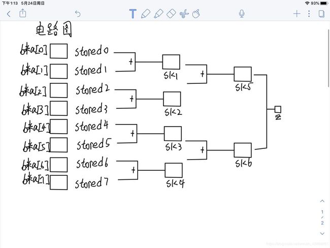
- 将b的每一位乘a数组得到结果左移相应的位数后逐级相加。
- 分频模块将50mhz的信号分解成200hz的信号
- 控制模块将输出分解成4组信号
- 4组信号刷新数码管
8位流水线乘法器,四个时钟周期得到结果:
module mulit_8bitspipelining(a,b,clk,rst,z);
	input	[7:0]a,b;
	input 	clk;
	input   rst;
	output  reg [15:0]z;

	reg [15:0] stored0;
	reg [15:0] stored1;
	reg [15:0] stored2;
	reg [15:0] stored3;
	reg [15:0] stored4;
	reg [15:0] stored5;
	reg [15:0] stored6;
	reg [15:0] stored7;

	reg [15:0] sk1;
	reg [15:0] sk2;
	reg [15:0] sk3;
	reg [15:0] sk4;
	reg [15:0] sk5;
	reg [15:0] sk6;
	always @(posedge clk or negedge rst) //clk 上升沿或 rst下降沿执行
		if (!rst)						//寄存器清零
			begin
				z<=0;
				stored0 <= 0;
				stored1 <= 0;
				stored2 <= 0;
				stored3 <= 0;
				stored4 <= 0;
				stored5 <= 0;
				stored6 <= 0;
				stored7 <= 0;
				sk1<=0;
				sk2<=0;
				sk3<=0;
				sk4<=0;
			end
		else
			begin
				if (a[0]==1) stored0<={8'b0,b};
				else 	stored0<=16'b0;
				if (a[1]==1) stored1<={7'b0,b,1'b0};
				else 	stored0<=16'b0;
				if (a[2]==1) stored2<={6'b0,b,2'b0};
				else 	stored0<=16'b0;
				if (a[3]==1) stored3<={5'b0,b,3'b0};
				else 	stored0<=16'b0;
				if (a[4]==1) stored4<={4'b0,b,4'b0};
				else 	stored0<=16'b0;
				if (a[5]==1) stored5<={3'b0,b,5'b0};
				else 	stored0<=16'b0;
				if (a[6]==1) stored6<={2'b0,b,6'b0};
				else 	stored0<=16'b0;
				if (a[7]==1) stored7<={1'b0,b,7'b0};
				else 	stored0<=16'b0;


				sk1<=stored0+stored1;
				sk2<=stored2+stored3;
				sk3<=stored4+stored5;//各级相加
				sk4<=stored6+stored7;

				sk5<=sk1+sk2;
				sk6<=sk3+sk4;

				z<=sk5+sk6;
			end

endmodule
分频模块:
module clkdivider(clk50mhz,rst,clk200hz );
	input clk50mhz;
	input rst;
	output reg clk200hz;

	reg [7:0] cnt; //内部节点

always@(posedge clk50mhz or negedge rst)
begin
	if(!rst)
		begin
		cnt			<= 	8'b0;
		clk200hz	<=	1'b0;
		end
	else  if (cnt < 8'd249)
		begin
		cnt			<= 	cnt + 1'b1;
		end
	else if (cnt == 8'd249)
		begin
		cnt			<= 	8'b0;
		clk200hz	<=	~clk200hz;
		end
end
endmodule
数码管控制模块
 module clkdivider(clk50mhz,rst,clk200hz );
	input clk50mhz;
	input rst;
	output reg clk200hz;

	reg [7:0] cnt; //内部节点

always@(posedge clk50mhz or negedge rst)
begin
	if(!rst)
		begin
		cnt			<= 	8'b0;
		clk200hz	<=	1'b0;
		end
	else  if (cnt < 8'd249)
		begin
		cnt			<= 	cnt + 1'b1;
		end
	else if (cnt == 8'd249)
		begin
		cnt			<= 	8'b0;
		clk200hz	<=	~clk200hz;
		end
end
endmodule
数码管控制模块:
module statecontrol (clk200hz,rst,z,out1,out2,out3,out4);
input clk200hz;
input rst;
input [15:0]z;
reg  [3:0]segdig;
reg  [3:0]segcontrol;
reg  [1:0]state;
output reg	 [7:0]out1;
output reg	 [7:0]out2;
output reg	 [7:0]out3;
output reg	 [7:0]out4;

always@(posedge clk200hz or negedge rst)
begin
	if(!rst)
		begin
		segdig			<= 	4'b0;
		segcontrol		<=	4'b0;
		state			<=	2'b0;
		end
	else
	begin
		case(state)
		2'b00:
			begin
			segdig		<=	z[3:0];
			segcontrol	<=	4'b0001;
			state		<=	state + 1'b1;
			end
		2'b01:
			begin
			segdig		<=	z[7:4];
			segcontrol	<=	4'b0010;
			state		<=	state + 1'b1;
			end
		2'b10:
			begin
			segdig		<=	z[11:8];
			segcontrol	<=	4'b0100;
			state		<=	state + 1'b1;
			end
		2'b11:
			begin
			segdig		<=	z[15:12];
			segcontrol	<=	4'b1000;
			state		<=	state + 1'b1;
			end
		endcase
	case(segcontrol)
	4'b0001:
	begin
	case(segdig)
	4'h0: out1[7:0]=8'b1000_0000;
	4'h1: out1[7:0]=8'b1111_1001;
	4'h2: out1[7:0]=8'b1010_0100;
	4'h3: out1[7:0]=8'b1011_0000;
	4'h4: out1[7:0]=8'b1001_1001;
	4'h5: out1[7:0]=8'b1001_0010;
	4'h6: out1[7:0]=8'b1000_0010;
	4'h7: out1[7:0]=8'b1111_1000;
	4'h8: out1[7:0]=8'b1000_0000;
	4'h9: out1[7:0]=8'b1001_0000;
	default: out1[7:0]=8'b1111_1111;
	endcase
	end
//second segment
	4'b0010:
	begin
	case(segdig)
	4'h0: out2[7:0]=8'b1000_0000;
	4'h1: out2[7:0]=8'b1111_1001;
	4'h2: out2[7:0]=8'b1010_0100;
	4'h3: out2[7:0]=8'b1011_0000;
	4'h4: out2[7:0]=8'b1001_1001;
	4'h5: out2[7:0]=8'b1001_0010;
	4'h6: out2[7:0]=8'b1000_0010;
	4'h7: out2[7:0]=8'b1111_1000;
	4'h8: out2[7:0]=8'b1000_0000;
	4'h9: out2[7:0]=8'b1001_0000;
	default: out2[7:0]=8'b1111_1111;
	endcase
	end
//third segment
	4'b0100:
	begin
	case(segdig)
	4'h0: out3[7:0]=8'b1000_0000;
	4'h1: out3[7:0]=8'b1111_1001;
	4'h2: out3[7:0]=8'b1010_0100;
	4'h3: out3[7:0]=8'b1011_0000;
	4'h4: out3[7:0]=8'b1001_1001;
	4'h5: out3[7:0]=8'b1001_0010;
	4'h6: out3[7:0]=8'b1000_0010;
	4'h7: out3[7:0]=8'b1111_1000;
	4'h8: out3[7:0]=8'b1000_0000;
	4'h9: out3[7:0]=8'b1001_0000;
	default: out3[7:0]=8'b1111_1111;
	endcase
	end
/
测试激励:
module test_SEG7_8x8time;
	reg[7:0] x,y;
	reg rst;
	reg clk50mhz;
	wire clk200hz;//
	wire[6:0] OSEG1,OSEG2,OSEG3,OSEG4;
	wire [15:0]z;

	//给定50mhz的时钟信号
	/* always
	begin
		clk50mhz = 1'b0;
		clk50mhz = #20 1'b1;
		#20;
	end */

	clkdivider outclk200hz(clk50mhz,rst,clk200hz);
	mulit_8bitspipelining finalmodule(x,y,clk200hz,rst,z);
	statecontrol  u0(clk200hz,rst,z,OSEG1,OSEG2,OSEG3,OSEG4);
	initial
	begin
		rst <= 1'b1;
		clk50mhz<=1'b0;
		x <=8'b0;
		y <=8'b0;
	#256 rst <= 1'b0;
	#200 rst <= 1'b1;
	#512 $stop();
	end
	always
	begin
	#2 clk50mhz<=~clk50mhz;
	end
	always
	begin
	#1
		x<=x+1;
		y<=y+1;
	#3;
	end

	initial
	begin
	$monitor($time,"X= %8b,Y= %8b ",x,y,"====%7b  ",OSEG4,
			"%7b  ",OSEG3,"%7b  ",OSEG2,"%7b  ",OSEG1);
	end
endmodule
实验结果

分频工作正常,4个时钟周期后出结果。