最低成本打造ros机器人底盘:ros系统与底盘stm32驱动板通信
MPRO 用于调试ros小车底盘,pid开发学学,电机驱动板反馈脉冲等数据的上位机工具。欢迎下载试用。
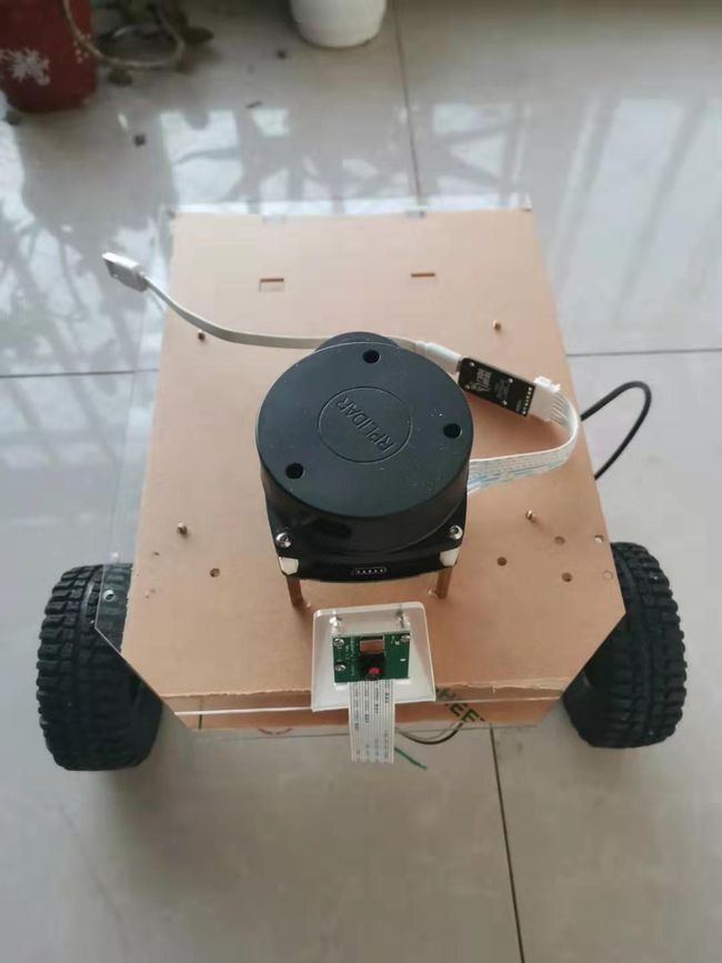
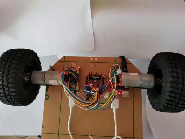
MPRO搭载stm32单片机驱动GA370编码电机,实现PID速度调节,转向控制。
实体图如下,采用杜邦线加模块设计。简单易用,可实现插拔,随意插拔适配。
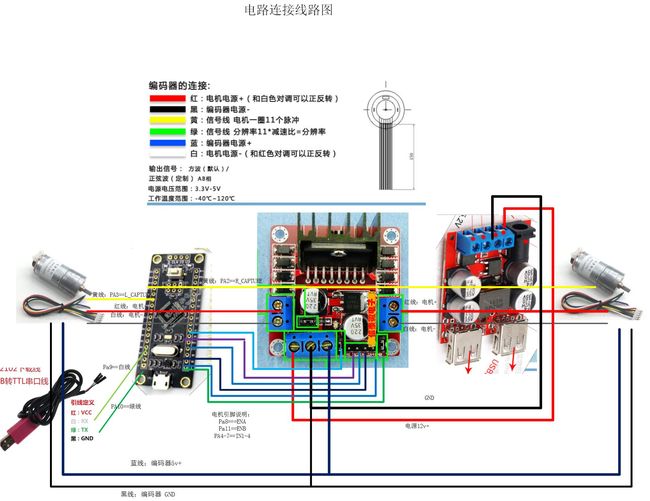
公开线路连接图,
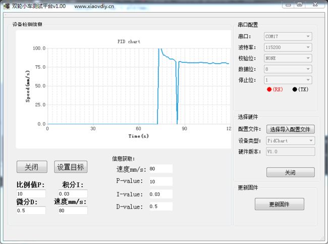
这里使用上位机软件进行pid调试
这里感谢miiboo 和http://stevenshi.me/
设计思路
有的朋友使用全向移动底座,有的使用两轮差动或四轮驱动实现移动底座;为了保持代码通用性,运动学解析这一部分没有特别的说明,移动底座只接收 x 与 y 两个方向的线速度以及一个绕 z 轴的角速度;针对不同的移动底座,还需要设计不同的运动学解析函数,以便于将线速度与角速度转变成电机运动指令,从而控制电机运动。ROS 部分实现一个节点,该节点订阅 cmd_vel 话题,并将该话题转变成 x y 两个方向的线速度以及一个绕 z 轴的角速度,通过串口发送到移动底座,即给STM32;另外该节点还需要发布导航需要的 odom 消息,这个消息需要移动底座提供,通过STM32的串口发送机器人的位置、速度、偏航角等信息,经过特殊的变换之后再发布。
stm32
串口1
//用于接收上位机的指令 ros位上位机
void USART1_IRQHandler(void)
{
if(USART_GetITStatus(USART1, USART_IT_RXNE) != RESET)
{
u8 tmp,ret ;
tmp = USART_ReceiveData(USART1);
ret = UART_CtlPkgRead(tmp);
if(ret ==0 )
uart1recflg =1;
}
}
参考MT法则,求编码速度这里编码速度只用到了单相。我们用TIMEr2就完成了测速和pid调节
u8 Ledflg=0;
unsigned int cnt=0;
extern u8 flg30s;
extern u8 count;
extern u8 switch2s;
double nLeft,nRight,nLeftO,nRightO;
void TIM2_IRQHandler(void)
{
static u8 start=0,start2=0; //开始计时标志
static u8 Z=11; //转动一圈脉冲数目
static u8 flag=0,flag2=0; //计数1S
static u32 pusleLCnt,pusleRcnt;
static u16 M1=0,N1=0; //单位时间内脉冲数
static u16 aTemp1=0,aTemp2=0; //赞存时间
static u16 count=0,count2=0,cnt=0; //中断计数
static u16 pulse_counter = 0; //脉冲计数
static u16 pulse_counter2 = 0; //脉冲计数
static double M2=0,N2=0; //单位时间内高频
static double f0=1000000; //频率1Mhz
static char ledflg =0;
static unsigned char pv=104;//减速比
//---------------------------------------------------------------
if(TIM_GetITStatus(TIM2, TIM_IT_Update) != RESET) //1ms 中断
{
if(cnt++==1000) //1s钟时间到
{
flag=1;
cnt=0;
if(ledflg ==0)
{
ledflg =1;
GPIO_SetBits(GPIOC, LED1_PIN);
} else
{
GPIO_ResetBits(GPIOC, LED1_PIN);
ledflg =0;
}
			}
			if(start==1)//如果第一个脉冲进来触发
			{
				if(count++==1000) //1s钟时间到
				{
					flag=1;
					count=0;

				}
				//------------------------------------------
				if(flag==1)  //
				{
					M1=pulse_counter; //得到脉冲个数
					wheelParam.RightPusle =pusleRcnt;
					aTemp1=pulse_counter;  //
					flag = 2; //
														//(脉冲总数/1圈的脉冲个数 )*πD /1S=转速
					wheelParam.RightSpeed = ((double)pusleRcnt /11/ pv)*314;//mm/s
					pusleRcnt =0;
				}
				//------------------------------------------
				if(flag==2)//
				{
					if(aTemp1!=pulse_counter)//下一个脉冲
					{
							start=0;
							M2=1000000+1000*count;        // 总时间1s+1ms*count
							nRight=(f0*M1)*60/(Z*M2);         //得到转速
							count=0;
							pulse_counter=0;
					}
				}
			}
			if(start2==1)//
            {
				if(count2++==1000) //1s钟时间到
				{
					flag2=1;
					count2=0;
				}
				//------------------------------------------
				if(flag2==1)  //
				{
					N1=pulse_counter2; //得到脉冲个数
					wheelParam.LeftPusle =      pusleLCnt;
					aTemp2=pulse_counter2;  //
					flag2 = 2; //
													//(脉冲总数/1圈的脉冲个数 )*πD /1S=转速
				    wheelParam.LeftSpeed = ((double)pusleLCnt /11/ pv)*314;//mm/s
				    pusleLCnt =0;
				}
				//------------------------------------------
				if(flag2==2)//
				{
					if(aTemp2!=pulse_counter2)//下一个脉冲
					{
						start2=0;
						N2=1000000+1000*count2;        // 总时间1s+1ms*count
						nLeft=(f0*N1)*60/(Z*N2);         //得到转速
						count2=0;
						pulse_counter2=0;
					}
				}
            }
    }
    TIM_ClearITPendingBit(TIM2, TIM_IT_Update  );
    //---------------------------------------------------------------
    if(TIM_GetITStatus(TIM2, TIM_IT_CC3) != RESET)  //right wheel 实际对应右车轮 PA2
    {
		pulse_counter++; //
		if(pulse_counter==1)//
		{
			flag=0;  //
			start=1; //
		}

		pusleRcnt ++;

	    TIM_ClearITPendingBit(TIM2, TIM_IT_CC3);
    }
	if(TIM_GetITStatus(TIM2, TIM_IT_CC4) != RESET) //实际对应左车轮 PA3
    {
		pulse_counter2++;
		if(pulse_counter2==1)
		{
			flag2=0;  //
			start2=1;
		}
	    pusleLCnt++;
		TIM_ClearITPendingBit(TIM2, TIM_IT_CC4);
    }
}
stm32将cmd_vel转换成左右论速度也是在 s’t’m32完成
left_vel = self.dx - self.dr * self.wheel_dist / 2 ;
right_vel = self.dx + self.dr * self.wheel_dist / 2;
self.dx是在x上的线速度。dr是绕z轴的角速度。wheel_dist是两个轮子之间的距离。这样就实现昂前进,左右转了。
在stm32上需要经过转换发布里程计
odometry.c 里程计计算
#include “odometry.h”
/*********************************************** 输出 *****************************************************************/
float position_x=0,position_y=0,oriention=0,velocity_linear=0,velocity_angular=0;
/*********************************************** 输入 *****************************************************************/
extern float odometry_right,odometry_left;//串口得到的左右轮速度
/*********************************************** 变量 *****************************************************************/
float wheel_interval= 268.0859f;// 272.0f; // 1.0146
//float wheel_interval=276.089f; //轴距校正值=原轴距/0.987
float multiplier=4.0f; //倍频数
float deceleration_ratio=90.0f; //减速比
float wheel_diameter=100.0f; //轮子直径,单位mm
float pi_1_2=1.570796f; //π/2
float pi=3.141593f; //π
float pi_3_2=4.712389f; //π3/2
float pi_2_1=6.283186f; //π2
float dt=0.005f; //采样时间间隔5ms
float line_number=4096.0f; //码盘线数
float oriention_interval=0; //dt时间内方向变化值
float sin_=0; //角度计算值
float cos_=0;
float delta_distance=0,delta_oriention=0; //采样时间间隔内运动的距离
float const_frame=0,const_angle=0,distance_sum=0,distance_diff=0;
float oriention_1=0;
u8 once=1;
/****************************************************************************************************************/
//里程计计算函数
void odometry(float right,float left)
{
if(once) //常数仅计算一次
{
const_frame=wheel_diameterpi/(line_numbermultiplier*deceleration_ratio);
const_angle=const_frame/wheel_interval;
once=0;
}
distance_sum = 0.5f*(right+left);//在很短的时间内,小车行驶的路程为两轮速度和
distance_diff = right-left;//在很短的时间内,小车行驶的角度为两轮速度差

//根据左右轮的方向,纠正短时间内,小车行驶的路程和角度量的正负
if((odometry_right>0)&&(odometry_left>0))            //左右均正
{
    delta_distance = distance_sum;
    delta_oriention = distance_diff;
}
else if((odometry_right<0)&&(odometry_left<0))       //左右均负
{
    delta_distance = -distance_sum;
    delta_oriention = -distance_diff;
}
else if((odometry_right<0)&&(odometry_left>0))       //左正右负
{
    delta_distance = -distance_diff;
    delta_oriention = -2.0f*distance_sum;
}
else if((odometry_right>0)&&(odometry_left<0))       //左负右正
{
    delta_distance = distance_diff;
    delta_oriention = 2.0f*distance_sum;
}
else
{
    delta_distance=0;
    delta_oriention=0;
}

oriention_interval = delta_oriention * const_angle;//采样时间内走的角度
oriention = oriention + oriention_interval;//计算出里程计方向角
oriention_1 = oriention + 0.5f * oriention_interval;//里程计方向角数据位数变化,用于三角函数计算

sin_ = sin(oriention_1);//计算出采样时间内y坐标
cos_ = cos(oriention_1);//计算出采样时间内x坐标

position_x = position_x + delta_distance * cos_ * const_frame;//计算出里程计x坐标
position_y = position_y + delta_distance * sin_ * const_frame;//计算出里程计y坐标

velocity_linear = delta_distance*const_frame / dt;//计算出里程计线速度
velocity_angular = oriention_interval / dt;//计算出里程计角速度

//方向角角度纠正
if(oriention > pi)
{
    oriention -= pi_2_1;
}
else
{
    if(oriention < -pi)
    {
        oriention += pi_2_1;
    }
}
}
ROS
需要设计一个 ROS 节点,该节点订阅 cmd_vel 话题,并发布 odom 消息;解析订阅的 cmd_vel 话题,转变成线速度以及角速度参数通过串口发送至移动底座;并实时监听串口送来的移动底座的位置、速度、偏航角等信息,整合成 odom 消息格式,发布出去。因为串口发送的都是16进制数据,因此涉及到浮点与16进制的转换,可以直接读内存实现:
1
2
3
4
5
//通过联合体获取浮点与16进制
typedef union{
             float fv;

             uint8_t cv[4];
}float_union;
串口发送的数据格式也就是移动底座接收数据包的格式可以定义为:
head
head
velocity_x
velocity_y
angular_v
CRC
0xff
0xff
float
float
float
unsigned char
velocity_x 表示 x 方向线速度,velocity_y 表示 y 方向线速度,angular_v 表示绕 z 轴的角速度,因为移动底座为贴地面运行,因此只有绕 z 轴的角速度,数据发送的总长度为15字节。
串口接收的数据格式也就是移动底座发送的数据包格式可以定义为:
head
head
x-position
y-position
x-speed
y-speed
angular-speed
pose-angular
CRC
0xaa
0xaa
float
float
float
float
float
float
u8
x-position 表示机器人实时 x 坐标位置,y-position表示机器人实时 y 坐标位置,x-velocity表示机器人实时 x 坐标方向速度,y-velocity表示机器人实时 y 坐标方向速度,angular velocity表示机器人当前角速度,pose angular表示机器人当前偏航角。数据上传的总长度为27字节。校验和从有效数据开始取异或即可,如下示例:
1
data[8] = data[2]data[3]data[4]data[5]data[6]^data[7];//不计算数据包的头
ROS 端串口的数据发送与数据读取可以参考站内文章ROS串口通信,需要注意的是在订阅 cmd_vel 话题时的回调函数中,参数类型选择 const geometry_msgs::Twist,另外在从串口获取到里程计信息后需要将偏航角转换成四元数才能进行发布:
偏航角转换成四元数才能发布
odom_quat = tf::createQuaternionMsgFromYaw(yaw.fvalue);
//发布坐标变换父子坐标系
odom_trans.header.frame_id = “odom”;
odom_trans.child_frame_id = “base_link”;
//发布tf坐标变换
odom_broadcaster.sendTransform(odom_trans);
//获取当前时间
current_time = ros::Time::now();
//载入里程计时间戳
odom.header.stamp = current_time;
//里程计位置数据
odom.pose.pose.position.x = posx.fvalue;
//载入线速度和角速度
odom.twist.twist.linear.x = vx.fvalue;
odom.twist.twist.angular.z = va.fvalue;
//发布里程计消息
read_pub.publish(odom);
ROS_INFO(“publish odometry”);
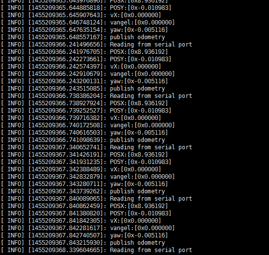
测试

原文链接:http://www.xiaovdiy.cn/?post=459
加入QQ群一起交流 ros机器人-gpscar定位
583302177