FPGA实现VGA显示图片
利用FPGA在带有VGA接口的液晶显示器上显示图片。
电路原理图:
端口说明: VGA_R2-VGAB0的8个端口位VGA的RGB数据位, VGA_HS为行同步信号,VGA_VS为场同步信号。
以分辨率为640x480为例,刷新速率为60Hz,每幅图像每行有800个clk,有525个行,完成一幅图像的时间是1s/60=16.6ms,完成一行的时间为16.6/525=31.75us,完成一个像素的时间约为31.75us/800=40ns(16.6/(525*800))。因此为了方便设计,接口时钟设置为25MHz,每个时钟送一个数据。
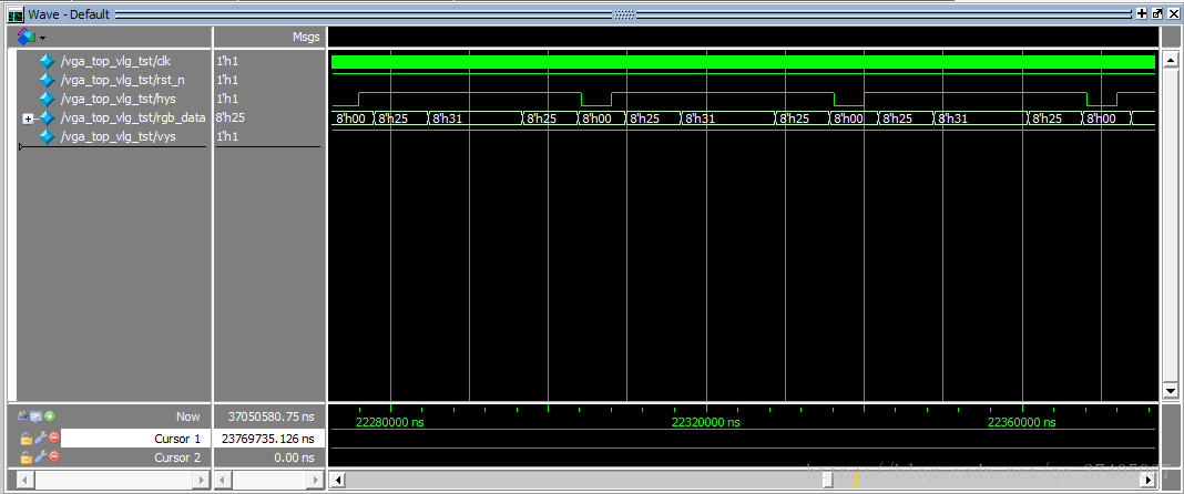
VGA时序图:
行信号的时序图如上图hys。行同步信号的低电平时间为96个clk,高电平期间延时45个clk后才能显示有效的数据,周期为800个clk。
场同步信号如上图vys。场同步信号低电平时间为2个行周期,两个低电平之间的时间为一帧画面。场同步信号确定数据显示点在哪一行,期间的484个行周期数据有效。每个有效的行周期时间内对应646个有效的数据点,所以分辨率为640x480。
VGA显示的时钟信号为25MHz是由PLL模块分频的到的。图片的数据存在FPGA的ROM中,VGA显示程序如下:
//VGA显示

module vga( clk_25M , rst_n ,
            hys , vys ,
			   rgb_data );

input clk_25M;     //25MHz时钟信号
input rst_n;       //复位信号
output hys;        //行同步信号
output vys;        //场同步信号
output [7:0] rgb_data; //RGB数据

reg hys;
reg vys;
reg [7:0] rgb_data;  //高3位R 中3位G 低2位B

//----------------------------------------------
//计数器

reg [9:0] cnt_hs;  //行信号clk计数
reg [9:0] cnt_vs;  //场信号clk计数

wire add_cnt_hs;   //行信号clk计数器加1条件
wire end_cnt_hs;   //行信号clk计数器结束条件

wire add_cnt_vs;   //场信号clk计数器加1条件
wire end_cnt_vs;   //场信号clk计数器结束条件

always @( posedge clk_25M or negedge rst_n ) begin
	if( !rst_n )
		cnt_hs <= 10'd0;
	else if( add_cnt_hs ) begin
		if( end_cnt_hs )
			cnt_hs <= 10'd0;
		else
			cnt_hs <= cnt_hs + 1'b1;
	end
end

assign add_cnt_hs = 1'b1;
assign end_cnt_hs = add_cnt_hs && ( cnt_hs == 800-1 );  //end_cnt_hs=1 结束计数

always @( posedge clk_25M or negedge rst_n ) begin
	if( !rst_n )
		cnt_vs <= 10'd0;
	else if( add_cnt_vs ) begin
		if( end_cnt_vs )
			cnt_vs <= 10'd0;
		else
			cnt_vs <= cnt_vs + 1'b1;
	end
end

assign add_cnt_vs = end_cnt_hs;
assign end_cnt_vs = add_cnt_vs && ( cnt_vs == 525-1 );

wire [9:0] vga_x;	//VGA的x坐标
wire [9:0] vga_y;	//VGA的y坐标

assign vga_x = cnt_hs - 10'd144;
assign vga_y = cnt_vs - 10'd35;

//-------------------------------------------------------------------
//行信号与场信号
always @( posedge clk_25M or negedge rst_n ) begin
	if( !rst_n )
		hys <= 1'b1;
	else if( cnt_hs == 10'd95 )
		hys <= 1'b1;
	else if( end_cnt_hs )
		hys <= 1'b0;
end

always @( posedge clk_25M or negedge rst_n ) begin
	if( !rst_n )
		vys <= 1'b1;
	else if( cnt_vs == 10'd1 )
		vys <= 1'b1;
	else if( end_cnt_vs )
		vys <= 1'b0;
end

//--------------------------------------------------------------
//rom存储

reg [14:0] bmp_rom_add;   //存储地址
wire [7:0] bmp_rom_data;	//图片rom的数据

snake Rom
(
	.clock( clk_25M ),
	.address( bmp_rom_add ),
	.q( bmp_rom_data	)
);
//---------------------------------------------------------------

`define picture_x 10'd150    //图片宽度
`define picture_y 10'd150    //图片高度

`define origin_x  10'd245    //图片显示起点(x,y)
`define origin_y  10'd150

wire	bmp_add;	//图片位置信号
wire  bmp_en;	//图片使能信号

//组合电路,用于生成图片位置信号
assign 	bmp_add = (vga_x >= `origin_x - 10'd3 ) && (vga_x < `origin_x + `picture_x - 10'd3 ) && (vga_y >= `origin_y) && (vga_y < `origin_y + `picture_y);
//组合电路,用于生成图片使能信号
assign 	bmp_en = (vga_x >= `origin_x) && (vga_x < `origin_x + `picture_x) && (vga_y >= `origin_y) && (vga_y < `origin_y + `picture_y);

//时序电路,用来给bmp_rom_add寄存器赋值
always @ (posedge clk_25M or negedge rst_n) begin
	if(!rst_n)
		bmp_rom_add <= 15'd0;

	else if( (vga_x == `origin_x - 10'd3) && (vga_y == `origin_y ) && bmp_add )  //图片起始点 地址清0
		bmp_rom_add <= 15'd0;

	else if(bmp_add)  //图片生成位置
		bmp_rom_add = bmp_rom_add + 1'b1;
end

//---------------------------------------------

//时序电路,用来给rgb_data寄存器赋值
always @ (posedge clk_25M or negedge rst_n) begin    //每个时钟上升沿赋值
	if(!rst_n)
		rgb_data <= 8'b0;
	else if( bmp_en )
		rgb_data <= bmp_rom_data;   //图片RGB数据
	else
		rgb_data <= 8'b000_000_00;
end

endmodule
在顶层模块中将50MHz时钟分频,对VGA模块例化
module game( clk , rst_n ,
             hys , vys , rgb_data ,
				 been );

input clk;
input rst_n;

output [7:0] rgb_data;    //VGA数据输出
output hys;
output vys;

output been;              //喇叭输出

wire clk_25M;
wire locked;

//------------------------------------------------------------

pll i2(
	.inclk0(clk),   //50MHz输入
	.c0(clk_25M),   //25Mhz输出
	.locked(locked) );

vga i1( .clk_25M(clk_25M) , .rst_n(rst_n) ,
        .hys(hys) , .vys(vys) ,
		  .rgb_data(rgb_data) );

endmodule
效果图:


