HDLBits 系列(40)如何写 TestBench 文件?
目录
- 序言
- 变量定义
- 时钟设计
- 设计输入
- 模块例化
- 实战演练
序言
由于入门的测试文件很简单,所以一直以来也都是直接给出测试文件,直到今天才想着去总结一个测试文件的写法。这篇博客将根据HDLBits的题目来总结如何书写Testbench文件,肯定有不完善的地方,仅仅作为一次总结吧。
TestBench文件,又称为TB文件,是用来对设计文件进行测试的程序,它与设计文件不同的地方在于,它使用的语法可以是不可综合的,比较灵活,不仅仅可以使用Verilog来写Tb文件,还可以使用其他语言,例如sv等。
写好一个基本的测试文件比较简单,但是写好一个比较完善的测试文件还是比较具有挑战性的。
Tb文件包括那些组件呢?
- 变量定义;
- 时钟生成;
- 待测试模块输入设计;
- 例化待设计模块。
那我们就开始吧。
变量定义
这个比较简单,所谓的变量定义,就是将待测试设计的输入在Tb文件中进行定义,方便后面对其数值进行设计。
待测试模块的输入定义为reg类型,因为我们要对其进行设计,输出定义为wire类型,它作为例化模块的输出,所以必须定义为wire类型。
例如,我们要测试一个D触发器:
module dff(
input clk,
input d,
input areset,
output q;
);
reg q_mid;
always@(posedge clk or posedge areset ) begin
	if(areset) q_mid <= 0;
	else q_mid <= d;
end
assign q = q_mid;
endmodule
我们在写测试文件的时候,对其输入输出进行定义,如下:
module test_dff();
// input define
reg clk;
reg d;
reg areset;
// output define
wire q;

//other parts
//......
endmodule
好了,这部分讲完了,进入下一部分,时钟生成。
时钟设计
对于时钟的设计,我们有两种写法,都是通过循环的方式来实现。
- forever
- always
第一种方式,也是我比较喜欢的方式,使用forever进行时钟的设计:
还是以上一个例子为例,待测试模块为dff:
module test_dff();
// input define
reg clk;
reg d;
reg areset;
// output define
wire q;

localparam PERIOD = 4;
// clk generate
initial begin
	clk = 0;
	forever
		# (PERIOD/2) clk = ~clk;
end
//other parts
//......
endmodule
可以看到,时钟生成部分很容易,需要注意的是必须在initial的内容进行输入的设计(时钟也属于输入),可以这么说,测试文件的reg(输入)几乎都是在initial内部完成的,这是一种有时间顺序的系列行为。
另一种方式是使用always的方式来设计时钟,如下:
module test_dff();
// input define
reg clk;
reg d;
reg areset;
// output define
wire q;

localparam PERIOD = 4;
// clk generate
initial begin
	clk = 0;
end
always begin
	#(PERIOD/2) clk = ~clk;
end

//other parts
//......
endmodule
可以看出区别,这种方式是在initial里面首先将clk初始化为0,之后在initial外部进行clk循环反转设计。
这是规则,需要严格遵守。
介绍完这两种方式之后,我们来看看HDLBits中对应这一部分的例题:
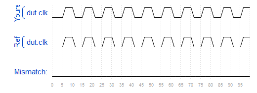
Tb/clock
原题复现:
You are provided a module with the following declaration:
module dut ( input clk ) ;
Write a testbench that creates one instance of module dut (with any instance name), and create a clock signal to drive the module’s clk input. The clock has a period of 10 ps. The clock should be initialized to zero with its first transition being 0 to 1.

好吧,给出我的设计:
module top_module ( );
    reg clk;
    initial begin
       clk = 0;
        forever
        #5 clk = ~clk;
    end

    dut inst_dut(
        .clk(clk)
    );

endmodule
设计输入
其实时钟也是输入,输入的设计和时钟的设计方式没有什么差别,只不过更加的多样化,我们可以使用task,function等等,当然也可以直接设计。
这里就不那么多废话了,突然感觉前面说了很多多余的东西,这里就怎么简单怎么来吧。
看这个例子:
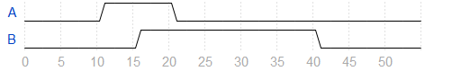
input design
原题复现:
Create a Verilog testbench that will produce the following waveform for outputs A and B:
我的设计:
module top_module ( output reg A, output reg B );//

    // generate input patterns here
    initial begin
        A = 0;
        B = 0;
        #10
        A = 1;
        #5
        B = 1;
        #5
        A = 0;
        #20
        B = 0;

    end

endmodule
当然,在实际写tb文件时候,肯定不是这样的整体格式,这里是为了适应做相应的题目需要。
实际中的格式是:
module top_module (  );//

    // generate input patterns here
    initial begin
        A = 0;
        B = 0;
        #10
        A = 1;
        #5
        B = 1;
        #5
        A = 0;
        #20
        B = 0;

    end

endmodule
模块例化
模块例化是测试文件中必须的,因为我们写测试文件的目的就是测试待测试模块。
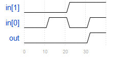
举个例子,我们下面来测试一个与门:
题目链接
You are given the following AND gate you wish to test:
module andgate (
    input [1:0] in,
    output out
);
Write a testbench that instantiates this AND gate and tests all 4 input combinations, by generating the following timing diagram:
我的设计:
module top_module();
    reg [1:0] in;
    wire out;

    initial begin
       in = 2'b00;
        #10
        in = 2'b01;
        #10
        in = 2'b10;
        #10
        in = 2'b11;
    end

    andgate inst(
        .in(in),
        .out(out)
    );

endmodule
实战演练
题目链接
The waveform below sets clk, in, and s:
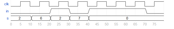
Module q7 has the following declaration:
module q7 (
    input clk,
    input in,
    input [2:0] s,
    output out
);
Write a testbench that instantiates module q7 and generates these input signals exactly as shown in the waveform above.
我的设计:
module top_module();

    reg clk;
    reg in;
    reg [2:0] s;
    wire out;

    initial begin
       clk = 0;
       forever begin
          #5 clk = ~clk;
       end
    end

    initial begin
    	in = 0;
        s = 2;
        #10
        s = 6;
        #10
        in = 1;
        s = 2;
        #10
        in = 0;
        s = 7;
        #10
        in = 1;
        s = 0;
        #30
        in = 0;
    end

    q7 inst(
        .clk(clk),
        .in(in),
        .s(s),
        .out(out)

    );


endmodule
在加上一个题目:
Tff testbench
You are given a T flip-flop module with the following declaration:
module tff (
    input clk,
    input reset,   // active-high synchronous reset
    input t,       // toggle
    output q
);
Write a testbench that instantiates one tff and will reset the T flip-flop then toggle it to the “1” state.
我的设计为:
module top_module ();

    reg clk;
    reg reset;
    reg t;
    wire q;

    initial begin
       clk = 0;
       forever
           #2 clk = ~clk;
    end

    initial begin
       reset = 1;
       t = 0;
       #4
       reset = 0;
        t = 1;

    end

    tff inst(
        .clk(clk),
        .reset(reset),
        .t(t),
        .q(q)
    );


endmodule
这篇博文就到这里吧,这是最基础,最简单的测试文件的写法,当然,基础很重要,在此基础上,才能够在上一层楼。