技术分享 | 避坑指南-无人机自主降落代码解析
前言 本主要讲解promtheus仿真环境中静态目标的自主降落, 涉及整体逻辑, 识别降落点, 坐标系变换. 不会涉及仿真环境搭建。本人之前的属于纯作计算机视觉工作的, 如果你和我一样在此之前没有接触过机器人控制, 无人机相关的内容, 那这篇文章对于入门prometheus的目标检测模块很适合, 视觉方面简单(opencv 写好的接口), 控制方面简单但全面。刚开始接触这方面知识, 如有错误请指正。
launch地址: Simulator/gazebo_simulator/launch_detection/sitl_landing_static_target.launch
promtheus自主降落-静态目标-仿真环境 静态目标自主降落的代码有3个部分组成仿真环境, 降落点识别, 控制逻辑组成。  重点关注在降落点识别模块, 即 prometheus_detection的landpad_det, 其次是逻辑控制 prometheus_mission的 autonomous_landing, 对于仿真环境部分为公有模块暂时忽略。
旋转矩阵, 坐标系变换不熟悉的强烈建议先看台大机器人学之运动学——林沛群的P2-P16部分。
网址: https://www.bilibili.com/video/BV1v4411H7ez?p=1
1、降落点识别 Prometheus/Modules/object_detection/cpp_nodes/landpad_det.cpp
输入:
- 图像数据: 用于识别降落点。
- 开关: 用于控制是否进行识别(暂时定主无人机)。
输出:
- 图像数据: 将检测结果画在原始图片上。
- 位置数据: 降落点在相机坐标系下的位置等信息。
- Debug信息。
流程:
- 获取数据。
- 调用ArUco Marker库识别对象,获得识别到Marker(二维码)的四个角位置, Marker ID对
- 筛选一个最好的Marker。
- 计算降落点: 计算, Marker对于相机坐标系的旋转矩阵, 以及Marker中心点在相机坐标系的坐标。
- 目标数据发布: 转化为prometheus_msgs::DetectionInfo格式的数据发布。
** 1.1 ArUco Marker** 官方: OpenCV: Detection of ArUco Markers 网址: https://docs.opencv.org/4.5.3/d5/dae/tutorial_aruco_detection.html
1.1.1 获取Marker的id, 坐标 // ArUco Marker字典选择以及旋转向量和评议向量初始化 Ptrcv::aruco::Dictionary dictionary = cv::aruco::getPredefinedDictionary(10) //------------------调用ArUco Marker库对图像进行识别-------------- // markerids存储每个识别到二维码的编号 markerCorners每个二维码对应的四个角点的像素坐标 std::vector markerids, markerids_deted; vector
- cv::aruco::getPredefinedDictionary(10) 获取一个 Marker_id --> Marker 字典. 参数(10)表示获取的那个字典, 不同的字典的区别在于Marker的大小不同。
- cv::aruco::DetectorParameters::create() 获取默认的识别器识别参数, 比如图像二值化阈值等。
- cv::aruco::detectMarkers(img, dictionary, markerCorners_deted, markerids_deted, parameters, rejectedCandidate)。 a)img 要识别的图像。 b) dictionary 和 parameters 上面定义的。 c)markerCorners_deted 保存Marker识别结果四个点的图片坐标系的坐。 d)markerids_deted 与 markerCorners_deted 一一对应的id。 e)rejectedCandidate 形状和Marker相似但不是Marker, 结构和markerCorners_deted一样。
1.1.2 计算旋转向量, 转移向量 旋转向量: 用于表示Marker在相机坐标系的姿态 偏移向量: 用于表示Marker在相机坐标系的位置 aruco::estimatePoseSingleMarkers(markerCornersONE, landpad_det_len * 0.133334, camera_matrix, distortion_coefficients, rvecs, tvecs);
- 第一个参数(MarkerCornersONE): Marker 四个角的坐标(图片坐标系为基)。
- 第二个参数(landpad_det_len * ....): Marker的实际大小。
- 第三, 四个参数(camera_matrix, distortion_coefficients)为相机的参数, 相机畸变参数。
- 最后两个参数为输出, 旋转向量, 偏移向量(以相机坐标系为基)。
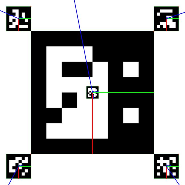
*1.2 Marker 筛选 * 降落板,以及每个Marker对应的id, 程序每次只处理一个Marker, 如果同时检测到多个Marker则各个Marker的优先级为: 43 --> 1,2,3,4 --> 19; 理想情况下在远处的无人机会最先发现最大的Marker 19, 然后检测到1,2,3,4 Marker调整位置, 最后检测到最小的Marker 43 提高降落位置精度。 
if (markerids_deted.size() > 0) { for (int tt = 0; tt < markerids_deted.size(); tt++) { if (19 == markerids_deted[tt]) { markerids.push_back(markerids_deted[tt]); markerCorners.push_back(markerCorners_deted[tt]); } } if (markerids.size() == 0) { for (int tt = 0; tt < markerids_deted.size(); tt++) { if (43 == markerids_deted[tt]) { markerids.push_back(markerids_deted[tt]); markerCorners.push_back(markerCorners_deted[tt]); } } } if (markerids.size() == 0) { for (int tt = 0; tt < markerids_deted.size(); tt++) { if (1 == markerids_deted[tt]) { markerids.push_back(markerids_deted[tt]); markerCorners.push_back(markerCorners_deted[tt]); } } } if (markerids.size() == 0) { for (int tt = 0; tt < markerids_deted.size(); tt++) { if (2 == markerids_deted[tt]) { markerids.push_back(markerids_deted[tt]); markerCorners.push_back(markerCorners_deted[tt]); } } } if (markerids.size() == 0) { for (int tt = 0; tt < markerids_deted.size(); tt++) { if (3 == markerids_deted[tt]) { markerids.push_back(markerids_deted[tt]); markerCorners.push_back(markerCorners_deted[tt]); } } } if (markerids.size() == 0) { for (int tt = 0; tt < markerids_deted.size(); tt++) { if (4 == markerids_deted[tt]) { markerids.push_back(markerids_deted[tt]); markerCorners.push_back(markerCorners_deted[tt]); } } } }
** 1.3 计算降落点** 旋转向量 --> 旋转矩阵 --> 旋转四元数
cv::Mat rotation_matrix; cv::Rodrigues(rvecs[0], rotation_matrix); Eigen::Matrix3d rotation_matrix_eigen; cv::cv2eigen(rotation_matrix, rotation_matrix_eigen); Eigen::Quaterniond q = Eigen::Quaterniond(rotation_matrix_eigen); q.normalize();
6个Maker下, 计算旋转矩阵 --> 降落点(相机坐标系为基)
if (19 == markerids[tt] || 43 == markerids[tt]) { id_to8_t[0] = 0.; id_to8_t[1] = 0.; id_to8_t[2] = 0.; } else if (1 == markerids[tt]) { id_to8_t[0] = -(landpad_det_len * 0.666667 + landpad_det_len * 0.133334) / 2.; id_to8_t[1] = (landpad_det_len * 0.666667 + landpad_det_len * 0.133334) / 2.; id_to8_t[2] = 0.; } else if (2 == markerids[tt]) { id_to8_t[0] = -(landpad_det_len * 0.666667 + landpad_det_len * 0.133334) / 2.; id_to8_t[1] = -(landpad_det_len * 0.666667 + landpad_det_len * 0.133334) / 2.; id_to8_t[2] = 0.; } else if (3 == markerids[tt]) { id_to8_t[0] = (landpad_det_len * 0.666667 + landpad_det_len * 0.133334) / 2.; id_to8_t[1] = -(landpad_det_len * 0.666667 + landpad_det_len * 0.133334) / 2.; id_to8_t[2] = 0.; } else if (4 == markerids[tt]) { id_to8_t[0] = (landpad_det_len * 0.666667 + landpad_det_len * 0.133334) / 2.; id_to8_t[1] = (landpad_det_len * 0.666667 + landpad_det_len * 0.133334) / 2.; id_to8_t[2] = 0.; }
cv::Mat id_to8_t_mat{id_to8_t}; id_to8_t_mat.convertTo(id_to8_t_mat, CV_32FC1);
rotation_matrix.convertTo(rotation_matrix, CV_32FC1); // cv::invert(rotation_matrix, rotation_matrix); 旋转向量 --> 旋转矩阵 + 偏移向量 // id_to8_mat 定位中心转换到纸面中心 // rotation_matrix * id_to8_t_mat 在Marker为基的坐标系下的坐标乘上,旋转向量等于在以相机坐标系下为基的坐标 cv::Mat id_8_t = rotation_matrix * id_to8_t_mat + vec_t_mat; // cv::Mat id_8_t = vec_t_mat;
最开始, 我一没有想明白 cv::Mat id_8_t = rotation_matrix * id_to8_t_mat + vec_t_mat id_to8_t_mat为什么前面没有负号, 如果没有负号, 无人机在看到1,2,3,4时会远离飞行, 而不会往中间飞。 
上图红色为x轴, 绿色为y轴皆指向正方向. 以右下角4号Marker为例子, id_to8_t_mat为正时, 计算得到的id_8_t不应该在4号的右下角去了, 而不会在左上角的中心了,
else if (4 == markerids[tt]) { id_to8_t[0] = (landpad_det_len * 0.666667 + landpad_det_len * 0.133334) / 2.; id_to8_t[1] = (landpad_det_len * 0.666667 + landpad_det_len * 0.133334) / 2.; id_to8_t[2] = 0.; } cv::Mat id_8_t = rotation_matrix * id_to8_t_mat + vec_t_mat;
直到看到 , "相机是朝向下方" 以及以下文字。"最后的坐标是要换算在机体坐标下的, 而不是在相机坐标系之下。”
关于坐标系转换的说明:识别算法发布的目标位置位于相机坐标系(从相机往前看,物体在相机右方x为正,下方y为正,前方z为正) 首先,从相机坐标系转换至机体坐标系(从机体往前看,物体在相机前方x为正,左方y为正,上方z为正):由于此demo相机朝下安装,且xy方向无偏移量。
pos_body_frame[0] = - Detection_raw.position[1]; pos_body_frame[1] = - Detection_raw.position[0]; pos_body_frame[2] = - Detection_raw.position[2];
2、控制逻辑 主要输入:
- 键盘控制指令
- 降落点坐标(相机坐标轴下): prometheus_msgs::DetectionInfo
- 无人机当前状态 prometheus_msgs::DroneState
主要输出:
- 无人机控制数据
- 无人机共有4种状态
enum EXEC_STATE { WAITING_RESULT, TRACKING, LOST, LANDING, };
初始时为WATING_RESULT状态, 等待降落点识别模块找到降落点, 找到降落点后进入TRACKING状态。
if(landpad_det.is_detected) { exec_state = TRACKING; message = "Get the detection result."; cout << message < 在TRACKING状态下, 如果当前不再悬停指令下且没有再找到降落点则转为LOST状态。 if(!landpad_det.is_detected && !hold_mode) { exec_state = LOST; message = "Lost the Landing Pad."; cout << message < 在TRACKING状态下, 如果机体离降落点的距离(欧式距离)小于阈值, 或则飞行高度过低, 进入LANDING状态。 // 抵达上锁点,进入LANDING distance_to_pad = landpad_det.pos_body_enu_frame.norm(); // 达到降落距离,上锁降落 if(distance_to_pad < arm_distance_to_pad) { exec_state = LANDING; message = "Catched the Landing Pad."; cout << message < 在TRACKING状态下, 如果未满足进入LANDING的条件, 则以机体距离降落点的距离设置的一定比例设置飞机的数据, 即机体离目标越远速度越快, 越近降落点速度越慢(机体惯性坐标系下) Command_Now.header.stamp = ros::Time::now(); Command_Now.Command_ID = Command_Now.Command_ID + 1; Command_Now.source = NODE_NAME; Command_Now.Mode = prometheus_msgs::ControlCommand::Move; Command_Now.Reference_State.Move_frame = prometheus_msgs::PositionReference::ENU_FRAME; Command_Now.Reference_State.Move_mode = prometheus_msgs::PositionReference::XYZ_VEL; //xy velocity z position for (int i=0; i<3; i++) { Command_Now.Reference_State.velocity_ref[i] = kp_land[i] * landpad_det.pos_body_enu_frame[i]; } // 如果目标也在移动, 则加上目标的速度 if(moving_target) { Command_Now.Reference_State.velocity_ref[0] += target_vel_xy[0]; Command_Now.Reference_State.velocity_ref[1] += target_vel_xy[1]; } 在LOST状态下, 机体原地向上飞行, 尝试找到降落点. 如果机体的高度在达到阈值高度仍然未找到目标, 则判定为定点降落失败, 并进入LANDING。 2.1 坐标系变换 从降落点识别模块获得降落点坐标是基于相机坐标系的, 需要处理转换为机体坐标系, 惯性坐标系下的点。 相机坐标系 --> 机体坐标系: camera_offset是相机距离机体质心的偏移量. 对于机体来说机头方向为x为正, 机体左边为y为正, 机体上方z为正。 // 识别算法发布的目标位置位于相机坐标系(从相机往前看,物体在相机右方x为正,下方y为正,前方z为正) // 相机安装误差 在mission_utils.h中设置 landpad_det.pos_body_frame[0] = -landpad_det.Detection_info.position[1] + camera_offset[0]; landpad_det.pos_body_frame[1] = -landpad_det.Detection_info.position[0] + camera_offset[1]; landpad_det.pos_body_frame[2] = -landpad_det.Detection_info.position[2] + camera_offset[2]; 机体系 -> 机体惯性系 (原点在机体的惯性系) (对无人机姿态进行解耦): R_Body_to_ENU, 机体坐标系到惯性坐标系的转移矩阵, 有飞机当前姿态(欧拉角) --> 转为旋转矩阵。 landpad_det.pos_body_enu_frame = R_Body_to_ENU * landpad_det.pos_body_frame; Eigen::Matrix3f get_rotation_matrix(float phi, float theta, float psi) { Eigen::Matrix3f R_Body_to_ENU; } 机体惯性系 --> 惯性系: 机体质心到惯性坐标系原点的偏移量。 landpad_det.pos_enu_frame[0] = _DroneState.position[0] + landpad_det.pos_body_enu_frame[0]; landpad_det.pos_enu_frame[1] = _DroneState.position[1] + landpad_det.pos_body_enu_frame[1]; landpad_det.pos_enu_frame[2] = _DroneState.position[2] + landpad_det.pos_body_enu_frame[2]; 结尾 最后作为这方面刚入门者, 总结下在阅读这部分代码时所踩的坑, 先简单过一遍代码, 忽略细节了解逻辑, 大概了解代码那些可以当作黑盒使用, 那些是需要深入的。对于需要深入的且之前未曾接触过的不要一来就直接看文章, 要先看相关视频。遇到和自己看法不同的代码, 先忽略往后面看代码有些时候答案就藏在后面, 如果还是为解决就再仔细阅读一遍代码相关的文章介绍。 技术发展的日新月异,阿木实验室将紧跟技术的脚步,不断把机器人行业最新的技术和硬件推荐给大家。看到经过我们培训的学员在技术上突飞猛进,是我们培训最大的价值。如果你在机器人行业,就请关注我们的公众号,我们将持续发布机器人行业最有价值的信息和技术。 阿木实验室致力于前沿IT科技的教育和智能装备,让机器人研发更高效!float r11 = cos(theta)*cos(psi);
float r12 = - cos(phi)*sin(psi) + sin(phi)*sin(theta)*cos(psi);
float r13 = sin(phi)*sin(psi) + cos(phi)*sin(theta)*cos(psi);
float r21 = cos(theta)*sin(psi);
float r22 = cos(phi)*cos(psi) + sin(phi)*sin(theta)*sin(psi);
float r23 = - sin(phi)*cos(psi) + cos(phi)*sin(theta)*sin(psi);
float r31 = - sin(theta);
float r32 = sin(phi)*cos(theta);
float r33 = cos(phi)*cos(theta);
R_Body_to_ENU << r11,r12,r13,r21,r22,r23,r31,r32,r33;
return R_Body_to_ENU;