Verilog学习笔记——入门
Verilog学习笔记
-
-
- 01 基本逻辑门代码设计与仿真
-
- Veriog基本逻辑门代码结构——以一位反相器为例
- ModelSim仿真基本流程
- 02 组合逻辑代码设计与仿真——多路选择器
-
- 二选一逻辑——assign问号冒号语句、always语句块
- 多路选择逻辑——case语句
- 03组合逻辑代码设计与仿真——补码转换和七段译码
-
- 补码转换
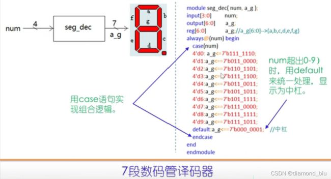
- 七段数码管译码
- 04 时序逻辑代码设计和仿真——计数器和伪随机码发生器
-
- 计数器
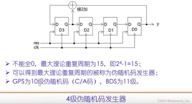
- 4级伪随机码发生器
- 05 时序逻辑代码设计和仿真——秒计数器
-
- 秒计数器
- 数码管0-9秒循环显示
- 数码管0-59秒循环显示
- 06 时序逻辑代码设计和仿真——相邻点累加
-
- 相邻16点相加输出
- 07 简单状态机代码设计——三角波发生器
-
- 三角波发生器
- 梯形波发生器
- 08 状态机代码设计与仿真——串口数据接收器
-
- 串口协议简介
- 串口数据接收模块
- 串口数据接收器
- 09 状态机代码设计与仿真——串口数据发送
-
- 串口数据发送模块
- 串口数据发送器
- 10 状态机代码设计与仿真——串口指令处理器
-
- 串口指令处理器
-
来源:B站《Verilog零基础入门——边看边练》——北京交通大学 李金城
01 基本逻辑门代码设计与仿真
Veriog基本逻辑门代码结构——以一位反相器为例
//2021-1-10,gyf
//反相器
`timescale 1ns/10ps //`timescale 时间单位/精度
module inv(A,Y);//module 名称(端口列表);
  input A;//输入端口,此处位宽为1,input[7:0] A;表示位宽为8
  output Y;//输出端口
  assign Y=~A;//assign组合逻辑赋值语句,定义Y与A的关系
endmodule

//-----testbench of inv----------
module inv_tb;//testbench模块,没有端口
reg aa;
wire yy;
//异名例化,A端口接aa,Y端口接yy
inv inv(
  .A(aa),
  .Y(yy));
//initial——end语句按时间为变量赋值,#10表示经过10个时间单位
initial begin
      aa<=0;//位宽为8时赋值:aa<=4'b00000000;
  #10 aa<=1;
  #10 aa<=0;
  #10 aa<=1;
  #10 $stop; //仿真停止,$stop语句为verilog系统任务
end
endmodule
ModelSim仿真基本流程
1.切换工作目录:File-Change Director
cd e://my_verilog
2.创建Library:File-New-Library,名称为work
//在当前目录创建逻辑库work
vlib work
//映射逻辑库名到指定的目录
vmap work work
3.编译:Compile选择inv.v,编译完成后可以看到work下两个module:inv与inv_tb,后者是top level module
vlog -reportprogress 300 -work work E:/my_verilog/inv.v
4.仿真:
选中inv_tb-右击-simulate
添加波形:Object窗口右击需要添加的波形-Add to-Wave-Signal in region
开始仿真:Restart-Run-All,即可在Wave窗口查看波形
结束仿真
vsim -voptargs=+acc work.inv_tb
add wave sim:/inv_tb/*
run -all
quit -sim
02 组合逻辑代码设计与仿真——多路选择器
二选一逻辑——assign问号冒号语句、always语句块
模块fn_sw:
- sel为0时,y时a和b的与;、
- sel为1时,y时a和b的异或。
//2022-1-11,gyf
//二选一逻辑
`timescale 1ns/10ps
module fn_sw(a,b,sel,y);
  input a,b,sel;
  output y;
  //使用assign语句实现组合逻辑
  //assign y=sel?(a^b):(a&b);

  //使用always语句块实现组合逻辑
  reg y;//always语句块里赋值的变量需要是reg型
  always @(a or b or sel) begin //敏感变量,组合逻辑输入
    //if-else语句二选一
    if(sel==1)begin
      y<=a^b;//reg型变量赋值用带箭头的等号!
    end
    else begin
      y=a&b;
    end
  end
endmodule

//-----testbench of fn_sw-----
module fn_sw_tb;
  reg a,b,sel;//对应输出定义为reg型,输出定义为wire型
  wire y;
  fn_sw fn_sw(
    .a(a),
    .b(b),
    .sel(sel),
    .y(y)) ;
  initial begin
        a<=0;b<=0;sel<=0;
    #10 a<=0;b<=0;sel<=1;
    #10 a<=0;b<=1;sel<=0;
    #10 a<=0;b<=1;sel<=1;
    #10 a<=1;b<=0;sel<=0;
    #10 a<=1;b<=0;sel<=1;
    #10 a<=1;b<=1;sel<=0;
    #10 a<=1;b<=1;sel<=1;
    #10 $stop;
  end
endmodule
多路选择逻辑——case语句
模块fn_sw_4:
- sel为00时,y时a和b的与;
- sel为01时,y时a和b的或;
- sel为10时,y时a和b的异或;
- sel为1时,y时a和b的同或。
//2022-1-11,gyf
//四选一逻辑
`timescale 1ns/10ps
module fn_sw_4(a,b,sel,y);
  input a,b;
  input[1:0] sel;
  output y;

  reg y;
  always @(a or b or sel) begin
    //case语句多路选择
    case(sel)
      2'b00: begin y<=a&b; end
      2'b01: begin y<=a|b; end
      2'b10: begin y<=a^b; end
      2'b11: begin y<=~(a^b); end
    endcase
  end
endmodule

//-----testbench of fn_sw_4-----
module fn_sw_4_tb;
  reg[3:0] absel;
  wire y;
  fn_sw_4 fn_sw_4(
    .a(absel[0]),
    .b(absel[1]),
    .sel(absel[3:2]),
    .y(y));
  initial begin
         absel<=4'b000;
    #200 $stop;
  end
  always #10 absel<=absel+1;//always #语句遍历逻辑值,每10个时间单位absle+1
endmodule
03组合逻辑代码设计与仿真——补码转换和七段译码
补码转换
//2022-1-11,gyf
//补码转换逻辑
`timescale 1ns/10ps
module comp_conv(a,a_comp);
  input[7:0] a;
  output[7:0] a_comp;
  //位拼接与二选一结合,简化逻辑
  a_comp=a[7]?{a[7],~a[6:0]+1},a;
endmodule

//-----testbench of comp_conv-----
module comp_conv_tb;
  reg[7:0] a_in;
  wire[7:0] y_out;
  comp_conv comp_conv(
    .a(a_in),
    .a_comp(y_out));
  initial begin
          a_in<=0;
    #3000 $stop;//2^8*10=2560
  end
  always #10 a_in<=a_in+1;
endmodule
仿真波形如下:
![]()
七段数码管译码
//2022-1-11,gyf
//七段数码管译码器
`timescale 1ns/10ps
module seg_dec(num,a_g);
  input[3:0] num;//0~9,四位
  output[6:0] a_g;
  reg[6:0] a_g;//a_g[6:0]-->{a,b,c,d,e,d,g}
  always @(num) begin
    case(num)
      4'd0:begin a_g<=7'b111_1110; end
      4'd1:begin a_g<=7'b011_0000; end
      4'd2:begin a_g<=7'b110_1101; end
      4'd3:begin a_g<=7'b111_1100; end
      4'd4:begin a_g<=7'b011_0011; end
      4'd5:begin a_g<=7'b101_1011; end
      4'd6:begin a_g<=7'b101_1111; end
      4'd7:begin a_g<=7'b111_0000; end
      4'd8:begin a_g<=7'b111_1111; end
      4'd9:begin a_g<=7'b111_1011; end
      default:begin a_g<=7'b000_0001;end//case的default部分,输入超出预期
    endcase
  end
endmodule

//-----testbench of seg_dec-----
module seg_dec_tb;
  reg[3:0] num;
  wire[6:0] a_g;
  seg_dec seg_dec(
    .num(num),
    .a_g(a_g));
  initial begin
         num<=0;
    #120 $stop;
  end
  always #10 num<=num+1;
endmodule
04 时序逻辑代码设计和仿真——计数器和伪随机码发生器
计数器
- 时序逻辑=组合逻辑+触发器
- always的敏感变量是时钟clock的上升沿或复位res的下降沿,这是时序逻辑的特点。只有到达时钟clock的上升沿或复位res的下降沿时,always才动,这是典型的**触发器(时钟信号、复位信号、边沿触发)**的结构。
- 在always部分赋值的变量定义为reg型
//2022-1-11,gyf
//计数器
`timescale 1ns/10ps
module counter(clk,res,y);
  input clk,res;
  output[7:0] y;
  reg[7:0] y;//!!!触发器定义为reg变量
  always @(posedge clk or negedge res) begin
    if(~res)begin//res下降为0时复位,因此正常计数时应为1
      y<=0;//触发器复位时的动作
    end
    else begin
      y<=y+1;//触发器正常工作时的状态
    end
  end
endmodule

//-----testbench of counter-------
module counter_tb;
  reg clk,res;
  wire[7:0] y;
  counter counter(
    .clk(clk),
    .res(res),
    .y(y));
  initial begin
          clk<=0;res<=0;
    #17 res<=1;//17个时间单位时开始计数
    #6000 $stop;
  end
  always #5 clk=~clk;//时钟周期为10个时间单位
endmodule
仿真波形如下:![[外链图片转存失败,源站可能有防盗链机制,建议将图片保存下来直接上传(img-rtmM18oE-1642093104018)(C:\Users\lenovo\Desktop\verilog学习笔记\捕获6.PNG)]](http://img.e-com-net.com/image/info8/a8bdbc3f862543a38fd9ff31acbf320a.jpg) 模拟信号输出(选中信号右键-format-analog(automatic)):8位计数器计数到255后从0在开始计数
模拟信号输出(选中信号右键-format-analog(automatic)):8位计数器计数到255后从0在开始计数

4级伪随机码发生器
- 不能全0,全0后模2加仍为0,因此复位信号不能为4b’0000,周期为15
- 寄存器右移高位给低位,不推荐使用”>>“写右移,写成d[2:0]<=d[3:1]
//2022-1-11,gyf
//四级伪随机码发生器
`timescale 1ns/10ps
module m_gen(clk,res,y);
  input clk,res;
  output y;
  reg[3:0] d;
  assign y=d[0];
  always @(posedge clk or negedge res) begin
    if(~res)begin
      d=4'b1111;
    end
    else begin
      d[2:0]=d[3:1];//右移一位
      d[3]<=d[3]+d[0];//模2加
    end
  end
endmodule

//-----testbench of m_gen-----
module m_gen_tb;
  reg clk,res;
  wire y;
  m_gen m_gen(
    .clk(clk),
    .res(res),
    .y(y));
  initial begin
        clk<=0;res<=0;
    #17 res<=1;//17个时间单位时开始生成伪随机序列
    #600 $stop;
  end
  always #5 clk=~clk;//时钟周期为10个时间单位
endmodule
05 时序逻辑代码设计和仿真——秒计数器
秒计数器
- 系统时钟24MHZ表示1s震荡24×106次,MHz(即1000kHz)
- 计数器从0~24×106-1计数,需要25位,每循环一次即为1s
- 设置触发器每看到0置1,非0置0,即得到秒脉冲
- 对秒脉冲计数,看到脉冲计数加一(0~9循环计数),由此得到秒计数器
//2022-1-13,gyf
//秒计数器
`timescale 1ns/10ps
module s_counter(clk,res,s_num);
  input clk,res;
  output[3:0] s_num;

  parameter frequency_clk=24;//设置参数表示24MHz
  reg[24:0] con_t;//秒脉冲分频计数器
  reg s_pulse;//秒脉冲尖
  reg[3:0] s_num;//虽然是输出端口,但若在always块里赋值仍需要定义为reg

  always@(posedge clk or negedge res) begin
    if(~res)begin
      con_t<=0;
      s_pulse<=0;//!!触发器记得写复位清零
      s_num=0;//!!同样触发器记得写复位
    end
    else begin
      //if(con_t==frequency_clk*1000000-1)begin//如果计数满,则重新计数
      if(con_t==frequency_clk*1000-1)begin//修改后变为24KHz
        con_t<=0;
      end
      else begin
        con_t<=con_t+1;//对时钟上升沿计数
      end

      if(con_t==0)begin//con_t每秒产生一个脉冲
        s_pulse<=1;
      end
      else begin
        s_pulse<=0;
      end

      if(s_pulse==1)begin//对脉冲计数,0~9循环计数
        if(s_num==9)begin//满9置0
          s_num<=0;
        end
        else begin
          s_num<=s_num+1;
        end
      end
    end
  end
endmodule

//-----testbench of s_counter------
module s_counter_tb;
  reg clk,res;
  wire[3:0] s_num;
  s_counter s_counter(
    .clk(clk),
    .res(res),
    .s_num(s_num));
  initial begin
        clk<=0;res<=0;
    #17 res<=1;//时钟复位解除
    #1000 $stop;
  end
  always #5 clk=~clk;
endmodule
由于24MHz数值过大,仿真很慢,clk过密。这里把分频系数缩小1000倍再仿真,仿真波形如下:


观察波形可以看到,每到达240000000ps=240000ns,即240000个单位时间,24000个clk系统时钟周期,con_t计数24000次,s_pulse出现一个脉冲,s_num加一1。
数码管0-9秒循环显示
//2022-1-13,gyf
//数码管0-9循环显示
`timescale 1ns/10ps
module top(clk,res,a_g);
  input clk,res;
  output[6:0] a_g;
  wire[3:0] s_num;//顶层模块内部信号,如果指示为了连接,定义为wire即可
  s_counter U1(//模块名 例化名
    .clk(clk),
    .res(res),
    .s_num(s_num));
  seg_dec U2(
    .num(s_num),//括号中为顶层信号名称,不是端口需定义为wire连接
    .a_g(a_g));
endmodule

//秒计数器
module s_counter(clk,res,s_num);
  input clk,res;
  output[3:0] s_num;

  parameter frequency_clk=24;//设置参数表示24MHz
  reg[24:0] con_t;//秒脉冲分频计数器
  reg s_pulse;//秒脉冲尖
  reg[3:0] s_num;//虽然是输出端口,但若在always块里赋值仍需要定义为reg

  always@(posedge clk or negedge res) begin
    if(~res)begin
      con_t<=0;
      s_pulse<=0;//!!触发器记得写复位清零
      s_num=0;//!!同样触发器记得写复位
    end
    else begin
      //if(con_t==frequency_clk*1000000-1)begin//如果计数满,则重新计数
      if(con_t==frequency_clk*1000-1)begin//修改后变为24KHz
        con_t<=0;
      end
      else begin
        con_t<=con_t+1;//对时钟上升沿计数
      end

      if(con_t==0)begin//con_t每秒产生一个脉冲
        s_pulse<=1;
      end
      else begin
        s_pulse<=0;
      end

      if(s_pulse==1)begin//对脉冲计数,0~9循环计数
        if(s_num==9)begin//满9置0
          s_num<=0;
        end
        else begin
          s_num<=s_num+1;
        end
      end
    end
  end
endmodule

//七段数码管译码器
module seg_dec(num,a_g);
  input[3:0] num;//0~9,四位
  output[6:0] a_g;
  reg[6:0] a_g;//a_g[6:0]-->{a,b,c,d,e,d,g}
  always @(num) begin
    case(num)
      4'd0:begin a_g<=7'b111_1110; end
      4'd1:begin a_g<=7'b011_0000; end
      4'd2:begin a_g<=7'b110_1101; end
      4'd3:begin a_g<=7'b111_1100; end
      4'd4:begin a_g<=7'b011_0011; end
      4'd5:begin a_g<=7'b101_1011; end
      4'd6:begin a_g<=7'b101_1111; end
      4'd7:begin a_g<=7'b111_0000; end
      4'd8:begin a_g<=7'b111_1111; end
      4'd9:begin a_g<=7'b111_1011; end
      default:begin a_g<=7'b000_0001;end//default部分,输入超出预期
    endcase
  end
endmodule

//-----testbench of top--------
module top_tb;
  reg clk,res;
  wire[6:0] a_g;
  top top(
    .clk(clk),
    .res(res),
    .a_g(a_g));
  initial begin
        clk<=0;res<=0;
    #17 res<=1;
    #30000 $stop;
  end
  always #5 clk=~clk;
endmodule
数码管0-59秒循环显示
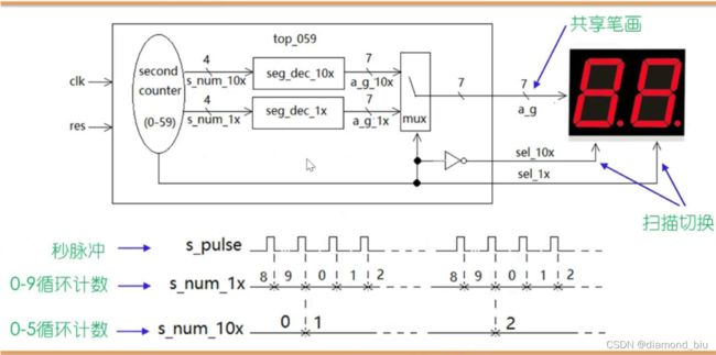
扫描切换这里不大理解是什么意思,怎么实现对两个数码管的控制呢。
06 时序逻辑代码设计和仿真——相邻点累加
相邻16点相加输出
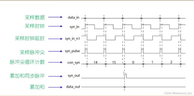
- 对输入的采样信号data_in求补码,对其升位,再进行16点相加后输出
- 为保证相加的节奏与采样时钟的节奏相同,对采样时钟的上升沿识别,获取其采样脉冲尖
- syn_in_n1是syn_in的反向延时,将syn_in&syn_in_n1得到syn_out采样脉冲尖,syn_out与data_in同时变化
- 对syn_pulse进行0-15计数,用于控制累加的节奏,每当计数器为15,将累加结果送入data_out,并产生累加和同步脉冲
一旦定义了触发器,就需要对其复位
//2022-1-13,gyf
//相邻16点相加
`timescale 1ns/10ps
module sigma_16p(clk,res,data_in,syn_in,data_out,syn_out);
  input clk,res;
  input[7:0] data_in;//采样信号
  input syn_in;//采样时钟
  output[11:0] data_out;//累加结果输出
  output syn_out;//累加结果同步脉冲

  reg syn_in_n1;//syn_in的反向延时,一旦定义了触发器就需要对其复位
  wire syn_pulse;//采样时钟上升沿识别脉冲,组合逻辑产生定义为wire
  assign syn_pulse=syn_in&syn_in_n1;
  reg[3:0] con_syn;//采样时钟循环计数器

  wire[7:0] comp_8;//补码
  wire[11:0] d_12;//升为12位
  assign comp_8=data_in[7]?{data_in[7],~data_in[6:0]+1}:data_in;//补码运算
  assign d_12={comp_8[7],comp_8[7],comp_8[7],comp_8[7],comp_8};//升位有符号扩展

  reg[11:0] sigma;//累加计算
  reg[11:0] data_out;//参与运算需要设置为reg
  reg syn_out;

  always@(posedge clk or negedge res) begin
    if(~res)begin
      syn_in_n1<=0;
      con_syn<=0;
      sigma<=0;
      syn_out<=0;
    end
    else begin
      syn_in_n1<=~syn_in;//输入时钟的反向延时
      if(syn_pulse)begin
        con_syn<=con_syn+1;//定义4位,满16自动溢出为1
      end

      if(syn_pulse)begin
        if(con_syn==15)begin
          sigma<=d_12;//计数满15时,d_12的结果已经送到,需要将其赋给sigma
          data_out<=sigma; //同时将sigma的结果送出到data_out
          syn_out=1;//还需要将syn_out置1,但syn_pulse很长时间才来一次,需要在其他时间置0
        end
        else begin
          sigma=sigma+d_12;
        end
      end
      else begin
        syn_out<=0;
      end
    end
  end
endmodule

//-----testbench of sigma_16p-------
module sigma_16p_tb;
  reg clk,res;
  reg[7:0] data_in;
  reg syn_in;
  wire[11:0] data_out;
  wire syn_out;
  sigma_16p sigma_16p(
    .clk(clk),
    .res(res),
    .data_in(data_in),
    .syn_in(syn_in),
    .data_out(data_out),
    .syn_out(syn_out));
  initial begin
        clk<=0;res<=0;data_in=1;syn_in=0;
    #17 res<=1;
    #5000 $stop;
  end
  always #5 clk<=~clk;
  always #100 syn_in<=~syn_in;//采样时钟
endmodule
仿真波形如下:
图中第一次data_out输出为15,这是因为后面计数时,con_syn计数满15时,d_12的结果已经送到,代码实现为sigma<=d_12,也即是说con_syn=0时,sigma已为1,而第一轮计数时,con_syn=0时sigma初值为0。
07 简单状态机代码设计——三角波发生器
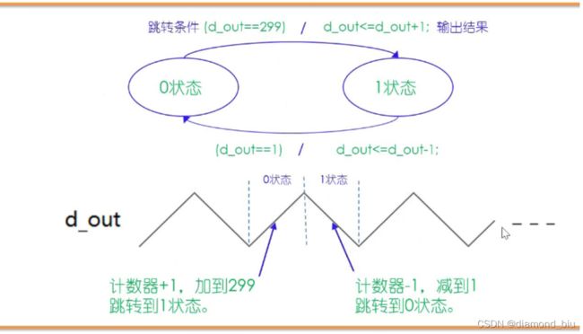
- 0状态:反复加1,直到299;
- 1状态:反复减1,直到1;
三角波发生器
//2022-1-13,gyf
//最简单的状态机:三角波发生器
`timescale 1ns/10ps
module tri_gen(clk,res,d_out);
  input clk,res;
  output[8:0] d_out;//累加到299,需要9位
  reg state;//定义主状态机寄存器,由于只有2个状态,1 bit即可
  reg[8:0] d_out;

  always@(posedge clk or negedge res)begin
    if(~res)begin
      state<=0;
      d_out<=0;
    end
    else begin
      case(state)
        0://上升
          begin
            //!!!当d_out=299时,+1与判断语句可理解为同步进行,即跳转到state 1时d_out=300
            d_out<=d_out+1;
            if(d_out==299)begin
              state<=1;
            end
          end
        1://下降
          begin
            //!!!同样当d_out=1时,-1与判断语句可理解为同步进行,即跳转到state 0时d_out=0
            d_out<=d_out-1;
            if(d_out==1)begin
              state<=0;
            end
          end
      endcase
    end
  end
endmodule

//----testbench of tri_gen------
module tri_gen_tb;
  reg clk,res;
  wire[8:0] d_out;
  tri_gen U1(
    .clk(clk),
    .res(res),
    .d_out(d_out));
  initial begin
        clk<=0;res<=0;
    #17 res<=1;
    #8000 $stop;
  end
  always #5 clk<=~clk;
endmodule
可以看到state 0上升,state 1下降。
![]()
此外,当state由0变为1时,d_out值为300,即加到299后跳转到1状态,波形的峰值为300,最低值为0。
梯形波发生器
存在3个状态:上升、平顶(200个周期)、下降,state需要2 bit,同时需要default
//2022-1-13,gyf
//最简单的状态机:三角波发生器
`timescale 1ns/10ps
module tri_gen(clk,res,d_out);
  input clk,res;
  output[8:0] d_out;//累加到299,需要9位
  reg[1:0] state;//定义主状态机寄存器,由于有3个状态,需要2 bit
  reg[8:0] d_out;

  reg[7:0] con;//计数器,记录平顶周期个数

  always@(posedge clk or negedge res)begin
    if(~res)begin
      state<=0;
      d_out<=0;
      con<=0;
    end
    else begin
      case(state)
        0://上升
          begin
            //!!!当d_out=299时,+1与判断语句可理解为同步进行,即跳转到state 1时d_out=300
            d_out<=d_out+1;
            if(d_out==299)begin
              state<=1;
            end
          end
        1://不变
          begin
            //当con=200时,跳转到2状态,同时con清0
            if(con==200)begin
              state<=2;
              con<=0;
            end
            else begin
              con<=con+1;
            end
          end
        2://下降
          begin
            //!!!同样当d_out=1时,-1与判断语句可理解为同步进行,即跳转到state 0时d_out=0
            d_out<=d_out-1;
            if(d_out==1)begin
              state<=0;
            end
          end
        default://
          begin
            state<=0;
            con<=0;
            d_out<=0;
          end
      endcase
    end
  end
endmodule

//----testbench of tri_gen------
module tri_gen_tb;
  reg clk,res;
  wire[8:0] d_out;
  tri_gen U1(
    .clk(clk),
    .res(res),
    .d_out(d_out));
  initial begin
        clk<=0;res<=0;
    #17 res<=1;
    #20000 $stop;
  end
  always #5 clk<=~clk;
endmodule
仿真波形如下:

可以看到state 0上升,state1持平,state 2下降。![]()

可以看到状态0变为状态1后的下一个时钟周期con开始从1计数,当计数为200时,状态1变为状态2,con清0。
实际处于峰值300的时间由202个时钟周期。
状态2与状态0之间再添加一个持平状态
//2022-1-13,gyf
//最简单的状态机:三角波发生器
`timescale 1ns/10ps
module tri_gen(clk,res,d_out);
  input clk,res;
  output[8:0] d_out;//累加到299,需要9位
  reg[1:0] state;//定义主状态机寄存器,由于有3个状态,需要2 bit
  reg[8:0] d_out;

  reg[7:0] con;//计数器,记录平顶周期个数

  always@(posedge clk or negedge res)begin
    if(~res)begin
      state<=0;
      d_out<=0;
      con<=0;
    end
    else begin
      case(state)
        0://上升
          begin
            //!!!当d_out=299时,+1与判断语句可理解为同步进行,即跳转到state 1时d_out=300
            d_out<=d_out+1;
            if(d_out==299)begin
              state<=1;
            end
          end
        1://不变
          begin
            //当con=200时,跳转到2状态,同时con清0
            if(con==200)begin
              state<=2;
              con<=0;
            end
            else begin
              con<=con+1;
            end
          end
        2://下降
          begin
            //!!!同样当d_out=1时,-1与判断语句可理解为同步进行,即跳转到state 0时d_out=0
            d_out<=d_out-1;
            if(d_out==1)begin
              state<=3;
            end
          end
        3://不变
          begin
            //当con=200时,跳转到2状态,同时con清0
            if(con==200)begin
              state<=0;
              con<=0;
            end
            else begin
              con<=con+1;
            end
          end
      endcase
    end
  end
endmodule

//----testbench of tri_gen------
module tri_gen_tb;
  reg clk,res;
  wire[8:0] d_out;
  tri_gen U1(
    .clk(clk),
    .res(res),
    .d_out(d_out));
  initial begin
        clk<=0;res<=0;
    #17 res<=1;
    #40000 $stop;
  end
  always #5 clk<=~clk;
endmodule
08 状态机代码设计与仿真——串口数据接收器
串口协议简介
- 串口发送端口空闲时为高:空闲识别
- 发送端口拉低表示数据传送开始:找下降沿确定开始传输
- 字节数据低位先发:b0先发,b7后发
- 字节发送后拉高表示字节传送结束
- 字节位宽可以不为8
- 常用波特率有4800、9600、115200,波特率表示每秒传送码元符号的个数,码元指携带数据信息的信号单元
串口数据接收模块
串口:指数据在有限的几个 IO 上按照顺序,一位一位的进行传输。串口是一个泛称,UART,TTL,RS232,RS485都遵循类似的通信时序协议,因此都被通称为串口,嵌入式里面说的串口,一般是指UART口。

- RX为串口输入
- data_out为接收到的串口字节
- 每接收完一个字节,en_data_out就产生一个同步脉冲
- 用户见到en_data_out即可收数
- 波特率4800,系统时钟频率24MHz,1秒传输4800个码元,1s震荡24000k次
串口数据接收器
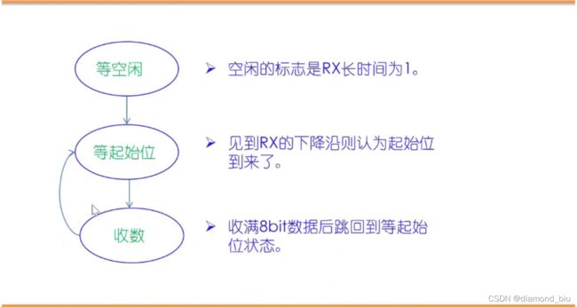
- 状态转换:等空闲-等起始位-接收b0b7-等起始位-接收b0b7…
- 空闲识别:RX长时间为1,这里规定连续接收15个1
- 找起始位:找RX下降沿,即~RX&RX_delay
- 在比特中间接收数据最可靠,因此等待1.5Tbit后开始接收b0,之后等待1Tbit接收,收满8bit后等起始位
- 24MHz,4800波特率,1s有24000000个时钟周期,传输4800个码元,每个码元的传输需要5000个时钟周期
//2022-2-15,gyf
//串口数据接收
`timescale 1ns/10ps
module UART_RXer(clk,res,RX,data_out,en_data_out);
  input clk,res,RX;
  output[7:0] data_out;//接收字节输出
  output en_data_out;//输出使能

  reg[7:0] data_out;//接收字节输出
  reg en_data_out;
  reg[3:0] state;//定义主状态机寄存器,10个状态,需4位
  reg[12:0] con;//计数器,用于计算比特宽度,5000周期/码元,con需要13位。1.5Tbit=7500,仍为13位。
  reg[3:0] con_bits;//用于计算比特数
  reg RX_delay;//RX的延时

  always@(posedge clk or negedge res)begin
    if(~res)begin
      state<=0;
      con<=0;
      con_bits<=0;
      RX_delay<=0;
      data_out<=0;
      en_data_out<=0;
    end
    else begin
      RX_delay<=RX;//RX延时
      case(state)
        0://等空闲
          begin
            if(con==4999)begin
             con<=0;
            end
            else begin
               con<=con+1;//5000个时钟周期接收一位
            end
            if(con==0)begin
              if(RX)begin
                con_bits<=con_bits+1;//空闲识别,RX=1时,连续接收12个1,con_bits计数
              end
              else begin
                con_bits<=0;
              end
            end
            if(con_bits==12)begin
              state<=1;//连续接收12个1,空闲状态0进入状态1
            end
          end
        1://等起始位
          begin
            en_data_out<=0;
            if(~RX&RX_delay)begin
              state<=2;//找起始位,RX下降沿
            end
          end
        2://收最低位b0,等1.5Tbits接收
          begin
            if(con==7499)begin
              con<=0;
              data_out[0]<=RX;
              state<=3;
            end
            else begin
              con<=con+1;
            end
          end
        3://收b1,等1Tbits接收
          begin
            if(con==4999)begin
              con<=0;
              data_out[1]<=RX;
              state<=4;
            end
            else begin
              con<=con+1;
            end
          end
        4://收b2
          begin
            if(con==4999)begin
              con<=0;
              data_out[2]<=RX;
              state<=5;
            end
            else begin
              con<=con+1;
            end
          end
        5://收3
          begin
            if(con==4999)begin
              con<=0;
              data_out[3]<=RX;
              state<=6;
            end
            else begin
              con<=con+1;
            end
          end
        6://收b4
          begin
            if(con==4999)begin
              con<=0;
              data_out[4]<=RX;
              state<=7;
            end
            else begin
              con<=con+1;
            end
          end
        7://收b5
          begin
            if(con==4999)begin
              con<=0;
              data_out[5]<=RX;
              state<=8;
            end
            else begin
              con<=con+1;
            end
          end
        8://收b6
          begin
            if(con==4999)begin
              con<=0;
              data_out[6]<=RX;
              state<=9;
            end
            else begin
              con<=con+1;
            end
          end
        9://收b7
          begin
            if(con==4999)begin
              con<=0;
              data_out[7]<=RX;
              state<=10;
            end
            else begin
              con<=con+1;
            end
          end
        10://产生使能脉冲后立即回到1状态
        begin
          en_data_out<=1;
          state<=1;
        end
        default://
          begin
            state<=0;
            con<=0;
            con_bits<=0;
            en_data_out<=0;
          end
      endcase
    end
  end
endmodule

//----testbench of UART_RXer-----
module UART_RXer_tb;
  reg clk,res,RX;
  wire[7:0] data_out;//接收字节输出
  wire en_data_out;//输出使能

  reg[25:0] RX_send;//人为设置的串口字节发送数据
  always @* begin
    RX=RX_send[0];//连接RX!!!
  end
  reg[12:0] con;

  UART_RXer UART_RXer(//同名例化,名称完全一致,无需.(aa)AA结构
    clk,res,RX,data_out,en_data_out);
  initial begin
    clk<=0;
    res<=0;
    RX_send<={1'b1,8'haa,1'b0,16'hffff};//设置右移发送,依次为:16个1、起始位0、01010101 1
    con<=0;
    #17 res<=1;
    #1000 $stop;
  end
  always #5 clk<=~clk;
  always@(posedge clk)begin
    if(con==4999)begin
      con<=0;
    end
    else begin
      con<=con+1;
    end
    if(con==0)begin
      RX_send<={RX_send[0],RX_send[25:1]};
    end
  end
endmodule
注意:一旦定义了reg就要复位。
09 状态机代码设计与仿真——串口数据发送
串口数据发送模块
- TX为串口输出端口
- rdy为空闲标志,字节发送时rdy为高
- data_in为准备发送的字节
- en_data_in为字节发送使能端口,高使能
- 发送波特率4800,系统时钟频率为24MHz
串口数据发送器
- 状态转换:等待发送使能-填充发送寄存器-发送寄存器右移
//2022-2-15,gyf
//串口数据发送
`timescale 1ns/10ps
module UART_TXer(clk,res,data_in,en_data_in,TX,rdy);
  input clk,res;
  input[7:0] data_in;//准备发送的数据
  input en_data_in;//发送使能
  output TX;
  output rdy;//空闲标志,0表示空闲

  reg state;//主状态机寄存器
  reg[9:0] send_buf;//发送寄存器
  assign TX=send_buf[0];//连接TX
  reg[12:0] con;//用于计算波特周期
  reg[9:0] send_flag;//用于判断右移结束
  reg rdy;//空闲标志,0空闲

  always @(posedge clk or negedge res) begin
    if(~res)begin
      state<=0;
      send_buf<=1;
      con<=0;
      send_flag<=10'b10_0000_0000;//值为1时右移结束
      rdy<=0;
    end
    else begin
      case(state)
        0://等待使能信号,填充发送寄存器
        begin
          if(en_data_in)begin
            send_buf<={1'b1,data_in,1'b0};
            send_flag<=10'b10_0000_0000;
            rdy<=1;
            state<=1;
          end
        end
        1://串口发送寄存器右移
        begin
          if(con==4999)begin
            con<=0;
          end
          else begin
            con<=con+1;
          end
          if(con==4999)begin
            send_buf<={send_buf[0],send_buf[9:1]};
            send_flag<={send_flag[0],send_flag[9:1]};
          end
          if(send_flag[0])begin
            rdy<=0;
            state<=0;//发送结束
          end
        end
      endcase
    end
  end
endmodule
//----testbench of UART_TXer----
module UART_TXer_tb;
  reg clk,res;
  reg[7:0] data_in;
  reg en_data_in;
  wire TX;
  wire rdy;
  UART_TXer UART_TXer(clk,res,data_in,en_data_in,TX,rdy);//同名例化
  initial begin
    clk<=0;
    res<=0;
    data_in<=8'h7f;
    en_data_in<=0;
    #17 res<=1;
    #30 en_data_in<=1;
    #10 en_data_in<=0;
    #1000 $stop;
  end
  always #5 clk<=~clk;
endmodule
仿真波形如下:
en_data_in冒尖,发送使能,填充send_buf={1’b1,data_in,1’b0},rdy<=1,同时进入state 1。
state 1中con计数,每5000周期send_buf左移一位。send_buf发生结束后,rdy<=0;

TX始终等于保持send_buf最低位,相当于每5000周期发送1位。

10 状态机代码设计与仿真——串口指令处理器
串口指令处理器
- 串口接收模块:接收指令和数据输入,并行输出
- 指令处理模块:对指令与数据处理,得到结果后并行输出
- 串口发送模块:指令运算结果输出
- 每次连续收到3个字节,第一个字节为指令cmd,第二、三个字节为操作数A、B
- 指令集如下:8’h0a : A+B; 8’h0b : A-B; 8’h0c : A&B; 8’h0d : A|B
状态转化:state 0 - state 1 - state 2 - state 0 - state 1 - state 2 - …
- state 0:接收指令和数据,见到en_din_pro为1则收数
- state 1:处理指令和数据,根据指令计算
- state 2:返回指令执行结果,返回计算结果
//2022-2-15,gyf
//指令处理器
module cmd_pro(clk,res,din_pro,en_din_pro,dout_pro,en_dout_pro,rdy);
  input clk,res;
  input[7:0] din_pro;//指令和数据输入端口
  input en_din_pro;//输入使能
  output[7:0] dout_pro;//指令执行结果
  output en_dout_pro;//指令输出使能
  output rdy;//串口发送模块空闲,0空闲

  parameter add_ab=8'h0a;
  parameter sub_ab=8'h0b;
  parameter and_ab=8'h0c;
  parameter or_ab=8'h0d;

  reg[2:0] state;//主状态机寄存器
  reg[7:0] cmd_reg,A_reg,B_reg;//存放指令、A、B;
  reg[7:0] dout_pro;
  reg en_dout_pro;

  always@(posedge clk or negedge res)begin
    if(~res)begin
      state<=0;
      cmd_reg<=0;
      A_reg<=0;
      B_reg<=0;
      dout_pro<=0;
      en_dout_pro<=0;
    end
    else begin
      case(state)
        0://等指令
        begin
          en_dout_pro<=0;
          if(en_din_pro)begin
            cmd_reg<=din_pro;
            state<=1;
          end
        end
        1://收操作数A
        begin
          if(en_din_pro)begin
            A_reg<=din_pro;
            state<=2;
          end
        end
        2://收操作数B
        begin
          if(en_din_pro)begin
            B_reg<=din_pro;
            state<=3;
          end
        end
        3://指令译码和运算执行
        begin
          state<=4;
          case(cmd_reg)
            add_ab:begin dout_pro<=A_reg+B_reg;end
            sub_ab:begin dout_pro<=A_reg-B_reg;end
            and_ab:begin dout_pro<=A_reg&B_reg;end
            or_ab:begin dout_pro<=A_reg|B_reg;end
          endcase
        end
        4://发送指令执行的结果
        begin
          if(~rdy)begin//rdy低,接收器空闲
            en_dout_pro<=1;
            state<=0;
          end
        end
        default://
        begin
          state<=0;
          en_dout_pro<=0;
        end
      endcase
    end
  end
endmodule
顶层封装模中,输入/信号均定义为wire,表示连接关系。不写逻辑。
//2022-2-15,gyf
//串口指令处理器
`timescale 1ns/10ps
module UART_top(clk,res,RX,TX);
  input clk,res,RX;
  output TX;

  wire[7:0] din_pro;
  wire en_din_pro;
  wire[7:0] dout_pro;
  wire en_dout_pro;
  wire rdy;

  UART_RXer UART_RXer(
    .clk(clk),
    .res(res),
    .RX(RX),
    .data_out(din_pro),
    .en_data_out(en_din_pro));
  UART_TXer UART_TXer(
    .clk(clk),
    .res(res),
    .data_in(dout_pro),
    .en_data_in(en_dout_pro),
    .TX(TX),
    .rdy(rdy));
  cmd_pro cmd_pro(//也可以直接同名例化
    .clk(clk),
    .res(res),
    .din_pro(din_pro),
    .en_din_pro(en_din_pro),
    .dout_pro(dout_pro),
    .en_dout_pro(en_dout_pro),
    .rdy(rdy));
endmodule

//----testbench of UART_top----
module UART_top_tb;
  reg clk,res;
  wire RX;
  wire TX;

  reg[45:0] RX_send;//里面装有串口字节发送数据
  assign RX=RX_send[0];
  reg[12:0] con;

  UART_top UART_top(clk,res,RX,TX);//同名例化
  initial begin
    clk<=0;
    res<=0;
    RX_send<={1'b1,8'h09,1'b0,1'b1,8'h06,1'b0,1'b1,8'h0a,1'b0,16'hffff};
    con<=0;
    #17 res<=1;
    #4000000 $stop;
  end
  always #5 clk=~clk;
  always@(posedge clk or negedge res)begin
    if(~res)begin
    end
    if(con==4999)begin
      con<=0;
    end
    else begin
      con<=con+1;
    end
    if(con==0)begin
      RX_send<={RX_send[0],RX_send[45:1]};
    end
  end
endmodule
仿真波形如下:
RX_send:ffff 0-0101-0000-1 0-0110-0000-1 0-1001-0000-1
按照串口通信协议,发送端口拉低表示数据开始传输,因此每字节数据以0开始,以1结尾。


