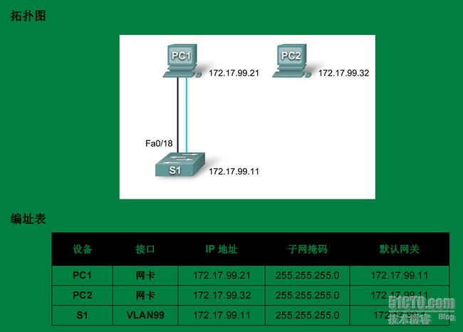
拓扑是官方下载的, 内容是我亲手实验的记录 希望大家可以参考
学习目标
1 检查检验默认配置
Switch#show version
Switch#show running-config
2创建基本交换机配置
3 配置口令
4保存结果并检验
Switch#show startup-config
一 理解交换机基本配置
1 Switch#show running-config 知道是24个快速以太网端口 2个G比特端口
Building configuration...
Current configuration : 925 bytes
!
version 12.2
no service password-encryption
!
hostname Switch
!
!
!
interface FastEthernet0/1
!
interface FastEthernet0/2
!
......
interface FastEthernet0/22
!
interface FastEthernet0/23
!
interface FastEthernet0/24
!
interface GigabitEthernet1/1
!
interface GigabitEthernet1/2
!
interface Vlan1
no ip address
shutdown
!
line con 0
!
line vty 0 4
login
line vty 5 15
login
!
!
End
2 Switch#show startup-config
startup-config is not present
3 Switch#show version 版本信息
Cisco IOS Software, C2960 Software (C2960-LANBASE-M), Version 12.2(25)FX, RELEASE SOFTWARE (fc1)
Copyright (c) 1986-2005 by Cisco Systems, Inc.
Compiled Wed 12-Oct-05 22:05 by pt_team
ROM: C2960 Boot Loader (C2960-HBOOT-M) Version 12.2(25r)FX, RELEASE SOFTWARE (fc4)
System returned to ROM by power-on
Cisco WS-C2960-24TT (RC32300) processor (revision C0) with 21039K bytes of memory.
24 FastEthernet/IEEE 802.3 interface(s)
2 Gigabit Ethernet/IEEE 802.3 interface(s)
64K bytes of flash-simulated non-volatile configuration memory.
Base ethernet MAC Address : 0060.47AC.1EB8
Motherboard assembly number : 73-9832-06
Power supply part number : 341-0097-02
4 Switch#show vlan
VLAN Name Status Ports
---- -------------------------------- --------- -------------------------------
1 default active Fa0/1, Fa0/2, Fa0/3, Fa0/4
Fa0/5, Fa0/6, Fa0/7, Fa0/8
Fa0/9, Fa0/10, Fa0/11, Fa0/12
Fa0/13, Fa0/14, Fa0/15, Fa0/16
Fa0/17, Fa0/18, Fa0/19, Fa0/20
Fa0/21, Fa0/22, Fa0/23, Fa0/24
Gig1/1, Gig1/2
10 VLAN10 active
30 VLAN30 active
1002 fddi-default active
1003 token-ring-default active
1004 fddinet-default active
1005 trnet-default active
二 对交换机进行基本的配置
1 设置登陆口令cisco 并使用登陆口令配置 vty线路 0 到 15
S1#configure terminal
Enter the configuration commands, one for each line. When you are finished,
return to global configuration mode by entering the exit command or pressing
Ctrl-Z.
S1(config)#line console 0
S1(config-line)#password cisco
S1(config-line)#login
S1(config-line)#line vty 0 15
S1(config-line)#password cisco
S1(config-line)#login
S1(config-line)#exit
2 设置特权口令密码为 class
S1(config)#enable secret class
3 创建便于在pc机上管理switch的vlan 99 这个是任意的
Switch(config)# vlan 99
Switch(config-vlan)#exit
Switch(config)# vlan 99
Switch(config-vlan)#exit
Switch(config)#inter vlan 99
%LINK-5-CHANGED: Interface Vlan99, changed state to upSwitch(config-if)#
Switch(config-if)#ip add 172.17.99.11 255.255.255.0
Switch(config-if)#no shut
Switch(config-if)#exit
Switch(config)#
%SYS-5-CONFIG_I: Configured from console by console
Switch#
4 将交换机的所有端口加入vlan 99
S1#configure terminal
S1(config)#interface range fa0/1 - 24
Switch(config-if-range)#switchport access vlan 99
%LINEPROTO-5-UPDOWN: Line protocol on Interface Vlan99, changed state to upSwitch(config-if-range)#exit
Switch(config)#
5 配置交换机的默认网关 注意是在全局配置模式下完成
Switch(config)# ip default-gateway 172.17.99.1
Switch(config)#
%SYS-5-CONFIG_I: Configured from console by console
6 查看管理lan 设置
Switch#show inter vlan 99
Vlan99 is up, line protocol is up
Hardware is CPU Interface, address is 0060.47ac.1eb8 (bia 0060.47ac.1eb8)
Internet address is 172.17.99.11/24
MTU 1500 bytes, BW 100000 Kbit, DLY 1000000 usec,
reliability 255/255, txload 1/255, rxload 1/255
Encapsulation ARPA, loopback not set
ARP type: ARPA, ARP Timeout 04:00:00
Last input 21:40:21, output never, output hang never
Last clearing of "show interface" counters never
Input queue: 0/75/0/0 (size/max/drops/flushes); Total output drops: 0
Queueing strategy: fifo
Output queue: 0/40 (size/max)
5 minute input rate 0 bits/sec, 0 packets/sec
5 minute output rate 0 bits/sec, 0 packets/sec
1682 packets input, 530955 bytes, 0 no buffer
Received 0 broadcasts (0 IP multicast)
0 runts, 0 giants, 0 throttles
0 input errors, 0 CRC, 0 frame, 0 overrun, 0 ignored
563859 packets output, 0 bytes, 0 underruns
0 output errors, 23 interface resets
0 output buffer failures, 0 output buffers swapped out
7 设置pc
PC1 172.17.99.21 255.255.255.0 172.17.99.11
PC2 172.17.99.22 255.255.255.0 172.17.99.11
S1 VLAN99 172.17.99.11 255.255.255.0 172.17.99.1
8 保存配置并检验
Switch#copy run start
Destination filename [startup-config]?
Building configuration...
[OK]
Switch#show startup-config
Using 1768 bytes
!
version 12.2
no service password-encryption
!
hostname Switch
!
enable secret 5 $1$mERr$9cTjUIEqNGurQiFU.ZeCi1
!
!
!
interface FastEthernet0/1
switchport access vlan 99
!
interface FastEthernet0/2
switchport access vlan 99
!
....
interface FastEthernet0/23
switchport access vlan 99
!
interface FastEthernet0/24
switchport access vlan 99
!
interface GigabitEthernet1/1
!
interface GigabitEthernet1/2
!
interface Vlan1
no ip address
shutdown
!
interface Vlan99
ip address 172.17.99.11 255.255.255.0
!
ip default-gateway 172.17.99.1
注意
!
line con 0
password cisco
login
!
line vty 0 4
password cisco
login
line vty 5 15
password cisco
login
!
!
end
pc2上检查
PC>ping 172.17.99.21
PC>ping 172.17.99.22
PC>ping 172.17.99.11
成功。。
