Verilog设计实例(5)详解全类别加法器(二)
文章目录
- 写在前面
- 正文
- 超前进位加法器
- 4位超前进位加法器
- 任意位宽的超前进位加法器
- 参考资料
- 交个朋友
写在前面
相关博文
个人博客首页
正文
超前进位加法器
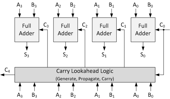
超前加法器由许多级联在一起的全加法器组成。 它仅通过简单的逻辑门就可以将两个二进制数相加。 下图显示了连接在一起以产生4位超前进位加法器的4个全加器。 超前进位加法器类似于纹波提前加法器。 不同之处在于,超前进位加法器能够在完全加法器完成其运算之前计算进位。 这比起波纹加法器具有优势,因为它能够更快地将两个数字加在一起。 缺点是需要更多逻辑。 您会发现在设计FPGA和ASIC时,执行速度和使用的资源之间通常会达到平衡。
所谓超前进位,就是在加法运算得到结果之前,得到进位,如何判断是否进位呢?
以上图为例给出三步判断:
- 如果Ai与Bi都为1,则一定进位,否则不一定进位;由此确定一定进位的情况,可以用与门实现。伪代码表示为:Gi = Ai & Bi;
- 第一步确定了一定进位的情况,这一步确定可能进位的情况,也就是Ai或Bi有一个1,可以使用或门判断,伪代码为:Pi = Ai | Bi;
- 这一步进一步确定第二部不确定的情况,如果低一位(进位用Ci表示,则低为可以表示为C_i-1)确定了进位,并且Pi为1,则一定进位,也即Ci = 1。
最后得到进位公式为:
C_(i+1) = G_i | ( P_i & C_i ) ;
由此得到的伪代码为:
  // Create the Generate (G) Terms:  Gi=Ai*Bi
  assign w_G[0] = i_add1[0] & i_add2[0];
  assign w_G[1] = i_add1[1] & i_add2[1];
  assign w_G[2] = i_add1[2] & i_add2[2];
  assign w_G[3] = i_add1[3] & i_add2[3];

  // Create the Propagate Terms: Pi=Ai+Bi
  assign w_P[0] = i_add1[0] | i_add2[0];
  assign w_P[1] = i_add1[1] | i_add2[1];
  assign w_P[2] = i_add1[2] | i_add2[2];
  assign w_P[3] = i_add1[3] | i_add2[3];

  // Create the Carry Terms:
  assign w_C[0] = 1'b0; // no carry input
  assign w_C[1] = w_G[0] | (w_P[0] & w_C[0]);
  assign w_C[2] = w_G[1] | (w_P[1] & w_C[1]);
  assign w_C[3] = w_G[2] | (w_P[2] & w_C[2]);
  assign w_C[4] = w_G[3] | (w_P[3] & w_C[3]);
4位超前进位加法器
逻辑设计
由上述原理,得到的逻辑设计Verilog代码为:
`timescale 1ns / 1ps
//////////////////////////////////////////////////////////////////////////////////
// Engineer: Reborn Lee
// Module Name: carry_lookahead_adder_4_bit
// Additional Comments:
// https://blog.csdn.net/Reborn_Lee
//////////////////////////////////////////////////////////////////////////////////
`include "full_adder.v"

module carry_lookahead_adder_4_bit
  (
   input [3:0]  i_add1,
   input [3:0]  i_add2,
   output [4:0] o_result
   );

  wire [4:0]    w_C;
  wire [3:0]    w_G, w_P, w_SUM;

  full_adder full_adder_bit_0
    (
      .i_bit1(i_add1[0]),
      .i_bit2(i_add2[0]),
      .i_carry(w_C[0]),
      .o_sum(w_SUM[0]),
      .o_carry()
      );

  full_adder full_adder_bit_1
    (
      .i_bit1(i_add1[1]),
      .i_bit2(i_add2[1]),
      .i_carry(w_C[1]),
      .o_sum(w_SUM[1]),
      .o_carry()
      );

  full_adder full_adder_bit_2
    (
      .i_bit1(i_add1[2]),
      .i_bit2(i_add2[2]),
      .i_carry(w_C[2]),
      .o_sum(w_SUM[2]),
      .o_carry()
      );

  full_adder full_adder_bit_3
    (
      .i_bit1(i_add1[3]),
      .i_bit2(i_add2[3]),
      .i_carry(w_C[3]),
      .o_sum(w_SUM[3]),
      .o_carry()
      );

  // Create the Generate (G) Terms:  Gi=Ai*Bi
  assign w_G[0] = i_add1[0] & i_add2[0];
  assign w_G[1] = i_add1[1] & i_add2[1];
  assign w_G[2] = i_add1[2] & i_add2[2];
  assign w_G[3] = i_add1[3] & i_add2[3];

  // Create the Propagate Terms: Pi=Ai+Bi
  assign w_P[0] = i_add1[0] | i_add2[0];
  assign w_P[1] = i_add1[1] | i_add2[1];
  assign w_P[2] = i_add1[2] | i_add2[2];
  assign w_P[3] = i_add1[3] | i_add2[3];

  // Create the Carry Terms:
  assign w_C[0] = 1'b0; // no carry input
  assign w_C[1] = w_G[0] | (w_P[0] & w_C[0]);
  assign w_C[2] = w_G[1] | (w_P[1] & w_C[1]);
  assign w_C[3] = w_G[2] | (w_P[2] & w_C[2]);
  assign w_C[4] = w_G[3] | (w_P[3] & w_C[3]);

  assign o_result = {w_C[4], w_SUM};   // Verilog Concatenation

endmodule // carry_lookahead_adder_4_bit
注:头文件中包含的全加器为:
`timescale 1ns / 1ps
//////////////////////////////////////////////////////////////////////////////////
// Engineer: Reborn Lee
// Module Name: full_adder
// https://blog.csdn.net/Reborn_Lee
//////////////////////////////////////////////////////////////////////////////////


module full_adder(
	input  i_bit1,
 	input  i_bit2,
 	input  i_carry,
	output o_sum,
 	output o_carry

    );


	assign o_sum   = i_bit1 ^ i_bit2 ^ i_carry;
        assign o_carry = ((i_bit1 ^ i_bit2) & i_carry) | (i_bit1 & i_bit2);


// More clear method

//   wire   w_WIRE_1;
//   wire   w_WIRE_2;
//   wire   w_WIRE_3;

//   assign w_WIRE_1 = i_bit1 ^ i_bit2;
//   assign w_WIRE_2 = w_WIRE_1 & i_carry;
//   assign w_WIRE_3 = i_bit1 & i_bit2;

//   assign o_sum   = w_WIRE_1 ^ i_carry;
//   assign o_carry = w_WIRE_2 | w_WIRE_3;


  // The third method
 // assign {o_carry, o_sum} = i_bit1 + i_bit2 + i_carry;


endmodule
功能仿真
`timescale 1ns/1ps
module carry_lookahead_adder_4_bit_tb;

   reg [3:0]  i_add1;
   reg [3:0]  i_add2;
   wire [4:0] o_result;


   initial begin
   	i_add1 = 'd5;
	i_add2 = 'd11;

	# 10
	i_add1 = 'd6;
	i_add2 = 'd15;

	# 10
	i_add1 = 'd11;
	i_add2 = 'd13;

	# 10
	i_add1 = 'd15;
	i_add2 = 'd15;

	#10 $finish;
   end


 // Monitor values of these variables and print them into the log file for debug
   initial
      $monitor ("i_add1 = %b, i_add2 = %b, o_result = %b", i_add1, i_add2, o_result);


   carry_lookahead_adder_4_bit inst_carry_lookahead_adder_4_bit(
   	.i_add1(i_add1),
   	.i_add2(i_add2),
   	.o_result(o_result)
   	);

endmodule
仿真波形及数据
i_add1 = 0101, i_add2 = 1011, o_result = 10000
i_add1 = 0110, i_add2 = 1111, o_result = 10101
i_add1 = 1011, i_add2 = 1101, o_result = 11000
i_add1 = 1111, i_add2 = 1111, o_result = 11110
任意位宽的超前进位加法器
逻辑设计
使用参数化的方式定义位宽为 WIDTH,且使用generate for循环语句来进行全加器例化以及进位产生,设计文件如下:
`include "full_adder.v"

module carry_lookahead_adder
  #(parameter WIDTH = 3)
  (
   input [WIDTH-1:0] i_add1,
   input [WIDTH-1:0] i_add2,
   output [WIDTH:0]  o_result
   );

  wire [WIDTH:0]     w_C;
  wire [WIDTH-1:0]   w_G, w_P, w_SUM;

  // Create the Full Adders
  genvar             ii;
  generate
    for (ii=0; ii
- 注意要对第一个进位进行置0,因为第一个全加器没有进位。
功能仿真
功能仿真同上一个tb文件类似,这里不在赘余了。
参考资料
- 参考资料1
- 参考资料2
交个朋友
-
个人微信公众号:FPGA LAB,左下角二维码;
-
知乎:李锐博恩,右下角二维码。

-
FPGA/IC技术交流2020

