PYNQ-关于PYNQ的GPIO的使用(RPI接口和arduino接口)或者常用的IO设备(如UART SPI IIC TIMER)
学习内容
- PYNQ的串口使用拓展
- GPIO的配置
- 类比配置别的IO功能
开发环境
PYNQ 这里我用的是2.3的官方镜像,jupyter-Notebook
官方文档参考
[https://pynq.readthedocs.io/en/latest/pynq_libraries.html#pynqmicroblaze]
1.PYNQ的串口使用拓展
前文提到了uart的配置的方式是用的RPI接口,下面我将简单说一下用arduino接口。别的地方的配置和前文的串口的配置相同吧,这里只需要把MBlibrary加载的ip改为arduino,如文:
lib = MicroblazeLibrary(base.ARDUINO, ['uart'])
device = lib.uart_open(0,1)
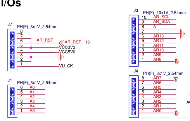
这里要说明下uart管脚的定义配置,这里是说如何进行编号:给出原理图

从右到左 从下到上由0 递增编号
AxiGPIO
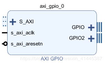
AxiGPIO类提供了从外部通用外围设备(如LED,按钮,使用AXI GPIO控制器IP连接到PL的开关)读取,写入和接收中断的方法。

AxiGPIO模块控制PL中AXI GPIO控制器的实例。每个AXI GPIO最多可具有两个通道,每个通道最多具有32个引脚。

read()和write()方法用于一个信道(所有的GPIO的)上读取和写入数据。
setdirection()并setlength()可以用来配置IP。方向可以是“内”,“外”和“内”。
默认情况下,方向是“ inout”。指定“入”或“出”将仅分别允许对IP进行读取和写入,而尝试读取 “出”或写入 “入”将导致错误。
可以将长度设置为仅写入较小范围的GPIO。
GPIO也可以视为数组。这允许设置特定的位,并且避免使用位掩码。
来自AXI GPIO 的中断信号ip2intc_irpt可以直接连接到AXI中断控制器,以在PS中引起中断。有关AsyncIO和中断的更多信息,请参见PYNQ和Asyncio 部分。
LED,Switch,Button和RGBLED类扩展了AxiGPIO控制器,并针对相应的外设进行了自定义。这些类期望[led|switch|button|rgbleds]_gpio 在与此类一起使用的覆盖中存在被称为的AXI GPIO实例。
例子
该示例仅用于说明,以显示如何使用AxiGPIO类。实际上,LED,按钮,开关和RGBLED类可用于扩展AxiGPIO类,这些类应用于覆盖层中的这些外设。
加载覆盖后,可以通过将AXI GPIO控制器的名称传递给该类来实例化AxiGPIO实例。
加载overlay:
from pynq import Overlay
from pynq.lib import AxiGPIO
ol = Overlay("base.bit")
配置io
led_ip = ol.ip_dict['gpio_leds']
switches_ip = ol.ip_dict['gpio_switches']
leds = AxiGPIO(led_ip).channel1
switches = AxiGPIO(switches_ip).channel1
简单的读写:
mask = 0xffffffff
leds.write(0xf, mask)
switches.read()
使用AXI GPIO作为数组:
switches.setdirection("in")
switches.setlength(3)
switches.read()
这种是官方给的AXI GPIO的例子,这里我没有经过实践验证,所以,我这里就不多说明。下面将介绍另外一种方法,和前文应用方式相同
MB调用GPIO

通样是打开官方的文档查看在MB里有哪些可以进行配置的操作,这里我们可以进行调用
GPIO Devices
GPIO devices allow for one or multiple pins to be read and written directly. All of these functions are in gpio.h
gpio type
A handle to one or more pins which can be set simultaneously.
gpio gpio_open(int pin)
Returns a new handle to a GPIO device for a specific pin on the I/O switch. This function can only be called if there is an I/O switch in the design.
gpio gpio_open_device(unsigned int device)
Returns a handle to an AXI GPIO controller based either on the base address or device index. The handle will allow for all pins on channel 1 to be set simultaneously.
gpio gpio_configure(gpio parent, int low, int hi, int channel)
Returns a new handle tied to the specified pins of the controller. This function does not change the configuration of the parent handle.
void gpio_set_direction(gpio device, int direction)
Sets the direction of all pins tied to the specified handle. The direction can either be GPIO_IN or GPIO_OUT.
void gpio_write(gpio device, unsigned int value)
Sets the value of the output pins represented by the handle. If the handle represents multiple pins then the least significant bit refers to the lowest index pin. Writing to pins configured as input has no effect.
unsigned int gpio_read(gpio device)
Reads the value of input pins represented by the handle, If the handle represents multiple pins then the least significant bit refers to the lowest index pin. Read from pins configured as output results in 0 being returned.
void gpio_close(gpio_device)
Returns the specified pins to high-impedance output and closes the device.
函数使用
这里我们需要用到的是gpio gpio_open(int pin),void gpio_set_direction(gpio device, int direction),void gpio_write(gpio device, unsigned int value),unsigned int gpio_read(gpio device)
这些函数比较好理解我就不过多说明了,直接看下配置程序:
首先加载官方的overlays,并且把mb.lib包含下:
from pynq.overlays.base import BaseOverlay
from pynq.lib import MicroblazeLibrary
base = BaseOverlay('base.bit')
print('finish')
打开GPIO
#如果用别的接口只需要把这里的RPI改为相应名称。
lib = MicroblazeLibrary(base.RPI, ['gpio'])
device = lib.gpio_open(14)
device1 = lib.gpio_open(15)
输入输出配置
gpio_set_direction(device, 1)#输入
gpio_set_direction(device1, 0)#输出
GPIO写操作
#只可以进行写0,写1
gpio_write(device, 1)
GPIO读操作
#可以用py打印下读到的值
read_num=gpio_write(device1)
print(read_num)
IO操作的拓展
其实可以从前文的uart和本文的gpio操作进行类比在官方文档中的配置,文档中都有详细的说明,只要慢慢啃就可以,这里像别的SPI IIC的io配置都可以类似这更改这里:
lib = MicroblazeLibrary(base.接口, ['设备'])
即可
比如这里如果想利用RPI的iic接口:
lib = MicroblazeLibrary(base.RPI, ['iic'])
如果想并用gpio和uart那么只需要在list增加即可,如:
lib = MicroblazeLibrary(base.RPI, ['gpio','uart'])
别的操作大家可以自己尝试,好了就为大家介绍到这里。