PYNQ-Z2 初识(十二) 自定义IP核,通过PWM IP核实现led呼吸灯
ip核是开发过程中非常重要的东西,我感觉就有点像是python的很多库一样。
除了xilinx提供的ip核外,我们还可以自定义ip核
此次参考ALINX_ZYNQ(我没打错)的开发教程做一个可以通过PWN控制LED的IP核心。
首先第一步肯定是创建工程和添加zynq
创建IP
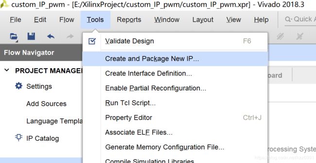
然后就是创建一个新的自定义ip了
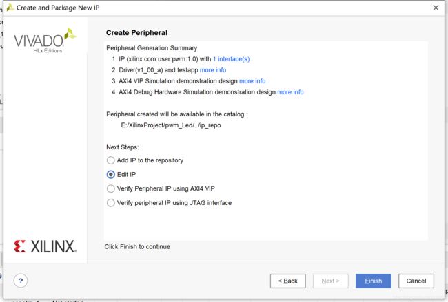
创建一个AXI4的外设

完成之后点击左侧的IP Catalog,可以找到刚才创建的IP,右键Edit in IP packager
之后会打开一个新的工程
IP核心内容
PWM
所谓PWM,指脉冲宽度调制,简单的讲就是生成一个宽度可变的方波,对于我们而言,可以通过计数阈值,计数器每到N就重置,那么N就控制了周期,然后计数器小于n大于0的时候输出高电平,大于n小于N的时候输出低电平,就控制了高电平的占比,也就是占空比。通过这种方式可以实现呼吸灯、电机调速等功能。
源文件的定义
点击Add source,添加一个叫pwm_generator.v的源文件,接口什么的咱们进文档去写。

既然是PWM,首先应该有个计数功能,我们定义几个变量:时钟clk,复位rst,使能en以及计数最大值period。
那么这块的内容应该有
always @(posedge clk or negedge rst)
	/***********计数功能***********/
	begin
		if(!rst)//如果复位就置0
			count <= 0;
		else if (count >= period - 1 || en == 0) // 溢出置0
			count <= 0;
		else
			count <= count + 1'b1; // 计数+1
	end
然后就是按照计数给输出端赋值了。我们还需要一个变量,比如输出高的时间或者占空比,这里我们用一个新的输入量hight_time代表高电平对应的计数,period是总的计数,其比值就是占空比。
always @(posedge clk or negedge rst)
	/***********PWM输出************/
	begin
		if(!rst) //复位
			pwm <= 0;
		else
			begin
				if (en == 0) //关闭使能
					pwm <= 0;
				else
					begin
						if(count < high_time)
							begin
								pwm <= 1;
							end
						else
							pwm <= 0;
					end
			end
	end
ok现在pwm模块就完成了,其完整内容为
`timescale 1ns / 1ps
//////////////////////////////////////////////////////////////////////////////////
// Company:
// Engineer: 战斗包子
//
// Create Date: 2020/07/16 16:21:58
// Design Name:
// Module Name: pwm_generator
// Project Name:
// Target Devices: PYNQ-Z2
// Tool Versions: Vivado 2018.3
// Description:
//
// Dependencies:
//
// Revision:
// Revision 0.01 - File Created
// Additional Comments:
//
//////////////////////////////////////////////////////////////////////////////////


module pwm_generator(
    input clk,
    input en,
    input rst,
	input [15:0] period,
	input [15:0] high_time,
    output reg pwm
	);

reg [31:0] count;

always @(posedge clk or negedge rst)
	/***********计数功能***********/
	begin
		if(!rst)//如果复位就置0
			count <= 0;
		else if (count >= period - 1 || en == 0) // 溢出罿0
			count <= 0;
		else
			count <= count + 1'b1; // 计数+1
	end

always @(posedge clk or negedge rst)
	/***********PWM输出************/
	begin
		if(!rst) //复位
			pwm <= 0;
		else
			begin
				if (en == 0) //关闭使能
					pwm <= 0;
				else
					begin
						if(count < high_time)
							begin
								pwm <= 1;
							end
						else
							pwm <= 0;
					end
			end
	end

endmodule
连接端口
到之前自动生成的文件中添加端口,此处有两个pwm_ctrl是为了控制两路输出pwm波。
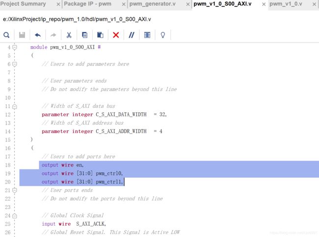
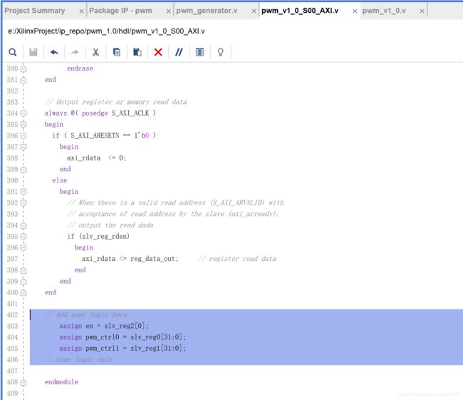
保存,然后转到top level开始调用模块,
比之前多了两个pwm的输出模块

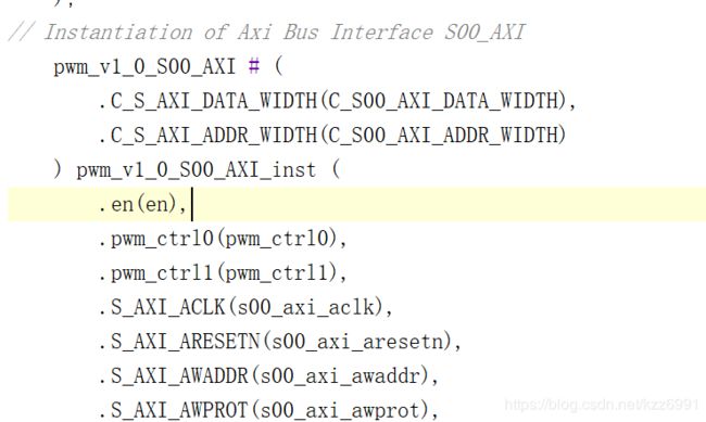
同样用户logic的地方也得改,那就是实例化我们的pwm发生器
    pwm_generator pwm0(
        .clk(s00_axi_aclk),
        .en(en),
        .rst(s00_axi_aresetn),
        .period(pwm_ctrl0[15:0]),
        .high_time(pwm_ctrl0[31:16]),
        .pwm(pwm_out0)
    );

    pwm_generator pwm1(
        .clk(s00_axi_aclk),
        .en(en),
        .rst(s00_axi_aresetn),
        .period(pwm_ctrl1[15:0]),
        .high_time(pwm_ctrl1[31:16]),
        .pwm(pwm_out1)
    );
此时可以保存综合一下,看看有没有报错(也不一定能全查出来。)
IP核打包
打开compent.xml,进入file Groups,点击Merge changes from file groups wizard

然后依次让左侧不是勾的都打勾。
最后Re-pakage IP
ok 一个船新的IP核就打包好了。
工程实现
create一个block design,然后添加zynq处理器以及刚刚生成的ip

这个pwm模块有两个控制端两个输出端,一个使能端,就和我们定义的一样,让它自动二连。
自动连线后,我们的pwm ip的axi总线部分连接了,但是右边我们自己定义的端口还没连。
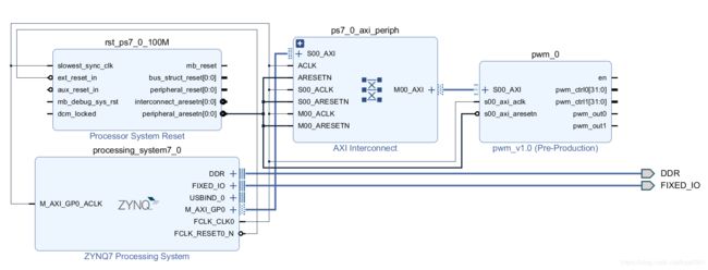
通过make external给pwm的out提供两个输出端
记得把名字改成pwm_out0和pwm_out1,不然的话一会改一下约束文件也可以。

然后右键system选择 generate output products

再create HDL wrapper
再添加约束,和之前的内容一样,输入
set_property -dict { PACKAGE_PIN R14   IOSTANDARD LVCMOS33 } [get_ports { pwm_out0 }];
set_property -dict { PACKAGE_PIN P14   IOSTANDARD LVCMOS33 } [get_ports { pwm_out1 }];
接下来老规矩,generate bitstream一波流
SDK
老规矩,export hardware(include bit stream),launch SDK
这次创建一个空应用工程
右键src,添加.c源文件
可以找到pwm0的内存地址是
![]()
pwm1的则是0x43c00004(寄存器的地址间隔为4)((为什么我也不知道))
我们定义第一个PWM的控制端口信号为
u32 pwm_gen0= 0x0BB81388;// 3000/5000
第二个端口为
u32 pwm_gen1= 0x07d01388; // 2000/5000
总程序为
#include 然后和之前一样烧写程序并运行c程序,可以看到led0和led1两个灯亮了,不过看不出来什么差别啊,我们修改一下,让占空比不断变化,并且通过串口打印占空比。
修改后的程序如下,占空比会从0逐渐到100再逐渐到0,可以观察到小灯闪烁的效果。
#include 参考资料
https://blog.csdn.net/qq_42263796/article/details/102156228

