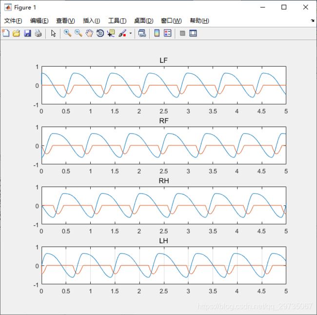
基于HOPF振荡器的CPG单元模型matlab实现
代码为实现仿生四足机器人技术(罗庆生等)中关于CPG网络控制模型的部分的绘图。
本人新手 代码不保证正确性
-
方程:

两种方法通用一个函数:
代码中变量含义:
a=![]() B=
B=![]() u=
u= ![]() Wsw=
Wsw=![]() W=
W=![]() th=
th=![]() Q=
Q=![]() A=a
A=a
x=[x1;y1;x2;y2......]
代码中的![]() 通过书中的公式 使用
通过书中的公式 使用![]() (占空比)来得出;相位关系可参照波士顿动力真的无可企及吗?一步步剖析四足机器人技术(一)中相关内容
(占空比)来得出;相位关系可参照波士顿动力真的无可企及吗?一步步剖析四足机器人技术(一)中相关内容
function dydt = f( t,x )
%F 此处显示有关此函数的摘要
%   此处显示详细说明
a=10000;
B=0.75;
u=0.4;
Wsw=5*pi;
A=100;

QLF=0;%1
QRH=0.25;%3 0.25

QRF=1;%2
QLH=1;%4

W1=(((1-B)/B)*Wsw)/(exp(-1*A*x(2))+1)+(Wsw/(exp(A*x(2))+1));
W2=(((1-B)/B)*Wsw)/(exp(-1*A*x(4))+1)+(Wsw/(exp(A*x(4))+1));
W3=(((1-B)/B)*Wsw)/(exp(-1*A*x(6))+1)+(Wsw/(exp(A*x(6))+1));
W4=(((1-B)/B)*Wsw)/(exp(-1*A*x(8))+1)+(Wsw/(exp(A*x(8))+1));

r1=x(1)^2+x(2)^2;
r2=x(3)^2+x(4)^2;
r3=x(5)^2+x(6)^2;
r4=x(7)^2+x(8)^2;


if QLH~=0
    QRF=B-QRH;
    QLH=B;
else
    if QLH==0
        QRF=QRH;
        QLH=QLF;
    end
end

%1行
%     QLF=0;%1
% QRH=0.25;%3
%
% QRF=0;%2
% QLH=0;%4
%     th11=0;
th11=2*pi*(QLF-QLF);
R11 = [cos(th11), -sin(th11);
    sin(th11), cos(th11)];

%th21=-pi;
th21=2*pi*(QLF-QRF);
R21 = [cos(th21), -sin(th21);
    sin(th21), cos(th21)];

%th31=-pi/2;
th31=2*pi*(QLF-QRH);
R31 = [cos(th31), -sin(th31);
    sin(th31), cos(th31)];

%     th41=-3*pi/2;
th41=2*pi*(QLF-QLH);
R41 = [cos(th41), -sin(th41);
    sin(th41), cos(th41)];

%2行
%     th12=pi;
th12=2*pi*(QRF-QLF);
R12 = [cos(th12), -sin(th12);
    sin(th12), cos(th12)];

%     th22=0;
th22=2*pi*(QRF-QRF);
R22 = [cos(th22), -sin(th22);
    sin(th22), cos(th22)];

%     th32=pi/2;
th32=2*pi*(QRF-QRH);
R32 = [cos(th32), -sin(th32);
    sin(th32), cos(th32)];

%     th42=-pi/2;
th42=2*pi*(QRF-QLH);
R42 = [cos(th42), -sin(th42);
    sin(th42), cos(th42)];

%3行
%     th13=pi/2;
th13=2*pi*(QRH-QLF);
R13 = [cos(th13), -sin(th13);
    sin(th13), cos(th13)];

%     th23=-pi/2;
th23=2*pi*(QRH-QRF);
R23 = [cos(th23), -sin(th23);
    sin(th23), cos(th23)];

%     th33=0;
th33=2*pi*(QRH-QRH);
R33 = [cos(th33), -sin(th33);
    sin(th33), cos(th33)];

%     th43=-pi;
th43=2*pi*(QRH-QLH);
R43 = [cos(th43), -sin(th43);
    sin(th43), cos(th43)];
%4行
%     th14=3*pi/2;
th14=2*pi*(QLH-QLF);
R14 = [cos(th14), -sin(th14);
    sin(th14), cos(th14)];

%     th24=pi/2;
th24=2*pi*(QLH-QRF);
R24 = [cos(th24), -sin(th24);
    sin(th24), cos(th24)];

%     th34=pi;
th34=2*pi*(QLH-QRH);
R34 = [cos(th34), -sin(th34);
    sin(th34), cos(th34)];

%     th44=0;
th44=2*pi*(QLH-QLH);
R44 = [cos(th44), -sin(th44);
    sin(th44), cos(th44)];


RR=[R11,R21,R31,R41;
    R12,R22,R32,R42
    R13,R23,R33,R43
    R14,R24,R34,R44];

FF=[a*(u-r1)*x(1)-W1*x(2);
    a*(u-r1)*x(2)+W1*x(1);
    a*(u-r2)*x(3)-W2*x(4);
    a*(u-r2)*x(4)+W2*x(3);
    a*(u-r3)*x(5)-W3*x(6);
    a*(u-r3)*x(6)+W3*x(5);
    a*(u-r4)*x(7)-W4*x(8);
    a*(u-r4)*x(8)+W4*x(7);
    ];
RR(abs(RR)-0<0.00001)=0;
temp=RR*x;
dydt=FF+RR*x;
matlab自带函数实现
使用ode45函数绘图
[t,y] = ode45(@f,[0 5],[0.1;0;0;0;0;0;0;0]);

%这里是膝关节处理
for i=1:length(y)
    if y(i,2)<=0
        y(i,2)=-1*sign(-1)*0.7067*y(i,2);
    else
        y(i,2)=0;
    end
    if y(i,4)<=0
        y(i,4)=-1*sign(-1)*0.7067*y(i,4);
    else
        y(i,4)=0;
    end
    if y(i,6)<=0
        y(i,6)=-1*sign(-1)*0.7067*y(i,6);
    else
        y(i,6)=0;
    end
    if y(i,8)<=0
        y(i,8)=-1*sign(-1)*0.7067*y(i,8);
    else
        y(i,8)=0;
    end
end

subplot(4,1,1)
plot(t,y(:,1),t,y(:,2));
subplot(4,1,2)
plot(t,y(:,3),t,y(:,4));
subplot(4,1,3)
plot(t,y(:,5),t,y(:,6));
subplot(4,1,4)
plot(t,y(:,7),t,y(:,8));
grid;
matlab手动欧拉法
out=[]%输出变量
count=1;
temp=f([],[0.1;0;0;0;0;0;0;0]);%后面参数为初值
y=zeros(8,1);
y=y+temp*0.0001;%0.0001为步长
for i=0:0.0001:5
    temp=f([],y);
    y=y+temp*0.0001;
    %处理膝关节
    if y(2)<=0
        out(count,2)=-1*sign(-1)*0.7067*y(2);
    else
        out(count,2)=0;
    end
    if y(4)<=0
        out(count,4)=-1*sign(-1)*0.7067*y(4);
    else
        out(count,4)=0;
    end
    if y(6)<=0
        out(count,6)=-1*sign(-1)*0.7067*y(6);
    else
        out(count,6)=0;
    end
    if y(8)<=0
        out(count,8)=-1*sign(-1)*0.7067*y(8);
    else
        out(count,8)=0;
    end
    out(count,1)=y(1);
    %out(count,2)=y(2);
    out(count,3)=y(3);
    %     out(count,4)=y(4);
    out(count,5)=y(5);
    %     out(count,6)=y(6);
    out(count,7)=y(7);
    %     out(count,8)=y(8);
    count=count+1;
end
t=0:0.0001:5;
%绘图
subplot(4,1,1)
plot(t,out(:,1),t,out(:,2));
title('LF')
subplot(4,1,2)
plot(t,out(:,3),t,out(:,4));
title('RF')
subplot(4,1,3)
plot(t,out(:,5),t,out(:,6));
title('RH')
subplot(4,1,4)
plot(t,out(:,7),t,out(:,8));
title('LH')
grid;

