- HDLBits刷题Day23,3.2.5.7 Simple FSM 3 (asynchronous reset) - 3.2.5.8 Simple FSM 3 (synchronous reset)
weixin_52312830
HDLBits刷题fpga开发算法硬件工程
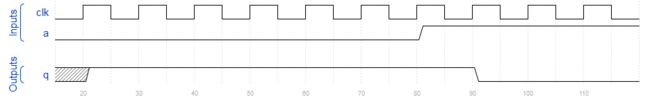
联系3.2.5.5和3.2.5.6来看3.2.5.7SimpleFSM3(asynchronousreset)问题描述下面是一输入一输出四状态的摩尔状态机的状态转移表。实现这个状态机。包括将FSM重置为状态A的异步重置。代码:moduletop_module(inputclk,inputin,inputareset,outputout);//reg[1:0]state,next_state;par
- HDLBits_Verilog刷题笔记Verilog Language Basics(一)
cascleright1
fpga开发硬件架构
前言这个刷题笔记是给自己复习巩固用的,包括自己在刷题的时候遇到的问题,思考,以及看了一些大佬的笔记和答案进行整理和扩充。git开源solutionshttps://github.com/viduraakalanka/HDL-Bits-Solutionsb站up脱发秘籍搬运工,呜呜这个up不管我学什么都有教程,永远也逃不开脱发的世界~https://space.bilibili.com/318808
- USTC Verilog OJ Solutions
Daniel_187
其他fpga开发VerilogHDLrisc-v
科大OJ其对应的英文版:HDLBits刷题网站01输出1moduletop_module(outputone);assignone=1;endmodule02输出0moduletop_module(outputzero);//Modulebodystartsaftersemicolonassignzero=0;endmodule03wiremoduletop_module(inputin,outp
- FPGA快速入门路径
zuoph
FPGA+人工智能电子技术fpga开发硬件工程
适合新手的FPGA入门路径总体路径规划基础学习-verilog语言verilog语言学习,推荐verilog数字系统设计一书,讲解比较详实和全面。练习推荐使用https://hdlbits.01xz.net/,将所有上面例题自己做一遍,便可做到初步掌握硬件设计语言的使用,想要精通还得自己多看多练,尤其是多练。基础学习-数字电路与系统这方面的书很多,推荐数字设计原理与实践一书,简单的过一遍,以后用到
- 「HDLBits题解」CS450
UESTC_KS
HDLBits题解fpga开发Verilog
本专栏的目的是分享可以通过HDLBits仿真的Verilog代码以提供参考各位可同时参考我的代码和官方题解代码或许会有所收益题目链接:Cs450/timer-HDLBitsmoduletop_module(inputclk,inputload,input[9:0]data,outputtc);reg[9:0]cnt;always@(posedgeclk)beginif(load)cnt<=data
- Verilog刷题[hdlbits] :Bcdadd100
卡布达吃西瓜
verilogfpga开发veriloghdlbits
题目:Bcdadd100YouareprovidedwithaBCDone-digitaddernamedbcd_faddthataddstwoBCDdigitsandcarry-in,andproducesasumandcarry-out.为您提供了一个名为bcd_fadd的BCD一位数加法器,它将两个BCD数字相加并带入,并生成一个和和并带入。modulebcd_fadd(input[3:0]
- Verilog刷题[hdlbits] :Adder100i
卡布达吃西瓜
verilogverilogfpga开发hdlbits
题目:Adder100iCreatea100-bitbinaryripple-carryadderbyinstantiating100fulladders.Theadderaddstwo100-bitnumbersandacarry-intoproducea100-bitsumandcarryout.Toencourageyoutoactuallyinstantiatefulladders,als
- 「HDLBits题解」Verification: Writing Testbenches
UESTC_KS
HDLBits题解fpga开发Verilog
本专栏的目的是分享可以通过HDLBits仿真的Verilog代码以提供参考各位可同时参考我的代码和官方题解代码或许会有所收益题目链接:Tb/clock-HDLBits`timescale1ps/1psmoduletop_module();parametertime_period=10;regclk;initialclk=0;alwaysbegin#(time_period/2)clk=~clk;e
- 「HDLBits题解」Build a circuit from a simulation waveform
UESTC_KS
HDLBits题解fpga开发Verilog
本专栏的目的是分享可以通过HDLBits仿真的Verilog代码以提供参考各位可同时参考我的代码和官方题解代码或许会有所收益题目链接:Sim/circuit1-HDLBitsmoduletop_module(inputa,inputb,outputq);//assignq=a&b;//Fixmeendmodule题目链接:Sim/circuit2-HDLBitsmoduletop_module(i
- 「HDLBits题解」Building Larger Circuits
UESTC_KS
HDLBits题解fpga开发Verilog
本专栏的目的是分享可以通过HDLBits仿真的Verilog代码以提供参考各位可同时参考我的代码和官方题解代码或许会有所收益题目链接:Exams/review2015count1k-HDLBitsmoduletop_module(inputclk,inputreset,output[9:0]q);always@(posedgeclk)beginif(reset)q=0)if(cnt<999)cnt
- 「HDLBits题解」Finite State Machines
UESTC_KS
HDLBits题解fpga开发Verilog
本专栏的目的是分享可以通过HDLBits仿真的Verilog代码以提供参考各位可同时参考我的代码和官方题解代码或许会有所收益题目链接:Fsm1-HDLBitsmoduletop_module(inputclk,inputareset,//AsynchronousresettostateBinputin,outputout);//parameterA=0,B=1;regstate,next_stat
- 【Verilog】HDLBits刷题 03 Verilog语言(2)(未完)
圆喵喵Won
fpga开发
二、模块(module)1.实例化Thefigurebelowshowsaverysimplecircuitwithasub-module.Inthisexercise,createoneinstanceofmodulemod_a,thenconnectthemodule'sthreepins(in1,in2,andout)toyourtop-levelmodule'sthreeports(wir
- 「HDLBits题解」Cellular automata
UESTC_KS
HDLBits题解fpga开发Verilog
本专栏的目的是分享可以通过HDLBits仿真的Verilog代码以提供参考各位可同时参考我的代码和官方题解代码或许会有所收益题目链接:Rule90-HDLBitsmoduletop_module(inputclk,inputload,input[511:0]data,output[511:0]q);always@(posedgeclk)beginif(load)q<=data;elseq<={1'
- 「HDLBits题解」Shift Registers
UESTC_KS
HDLBits题解fpga开发Verilog
本专栏的目的是分享可以通过HDLBits仿真的Verilog代码以提供参考各位可同时参考我的代码和官方题解代码或许会有所收益题目链接:Shift4-HDLBitsmoduletop_module(inputclk,inputareset,//asyncactive-highresettozeroinputload,inputena,input[3:0]data,outputreg[3:0]q);a
- 「HDLBits题解」Latches and Flip-Flops
UESTC_KS
HDLBits题解fpga开发Verilog
本专栏的目的是分享可以通过HDLBits仿真的Verilog代码以提供参考各位可同时参考我的代码和官方题解代码或许会有所收益题目链接:Dff-HDLBitsmoduletop_module(inputclk,//Clocksareusedinsequentialcircuitsinputd,outputregq);////Useaclockedalwaysblock//copydtoqatever
- 「HDLBits题解」Counters
UESTC_KS
HDLBits题解fpga开发Verilog
本专栏的目的是分享可以通过HDLBits仿真的Verilog代码以提供参考各位可同时参考我的代码和官方题解代码或许会有所收益题目链接:Count15-HDLBitsmoduletop_module(inputclk,inputreset,//Synchronousactive-highresetoutput[3:0]q);always@(posedgeclk)beginif(reset)q<=0;
- verilog语法进阶
FPGA中国创新中心
FPGA学习fpga开发verilogfpga硬件工程
文章目录前言一、always块(alwaysblock)二、if语句三、case语句四、casez语句五、三目运算(ternaryconditionaloperator)六、递减运算符(reduction)七、for循环语句八、实例化多个模块(generate)总结前言 本文是针对verilog基础语法做进一步的学,通过网站HDLbits中的代码和例子来展开本文要讨论的内容。HDLbits是一个
- 「HDLBits题解」Popcount255
UESTC_KS
HDLBits题解Verilog
本专栏的目的是分享可以通过HDLBits仿真的Verilog代码以提供参考各位可同时参考我的代码和官方题解代码或许会有所收益题目链接:Popcount255-HDLBitsmoduletop_module(input[254:0]in,outputreg[7:0]out);integeri;always@(*)beginout=0;for(i=0;i>i&1)out=out+1;elseout=o
- 「HDLBits题解」Adder100i
UESTC_KS
HDLBits题解Verilog
本专栏的目的是分享可以通过HDLBits仿真的Verilog代码以提供参考各位可同时参考我的代码和官方题解代码或许会有所收益题目链接:Adder100i-HDLBitsmoduletop_module(input[99:0]a,b,inputcin,output[99:0]cout,output[99:0]sum);add1Add0(a[0],b[0],cin,sum[0],cout[0]);ge
- 「HDLBits题解」Ringer
UESTC_KS
HDLBits题解Verilog
本专栏的目的是分享可以通过HDLBits仿真的Verilog代码以提供参考各位可同时参考我的代码和官方题解代码或许会有所收益题目链接:Ringer-HDLBitsmoduletop_module(inputring,inputvibrate_mode,outputringer,//Makesoundoutputmotor//Vibrate);assignmotor=vibrate_mode?(ri
- 「HDLBits题解」Bcdadd100
UESTC_KS
HDLBits题解Verilog
本专栏的目的是分享可以通过HDLBits仿真的Verilog代码以提供参考各位可同时参考我的代码和官方题解代码或许会有所收益题目链接:Bcdadd100-HDLBitsmoduletop_module(input[399:0]a,b,inputcin,outputcout,output[399:0]sum);wire[99:0]t;genvari;bcd_faddu0(a[3:0],b[3:0],
- 【Verilog】HDLBits题解——Circuits/Sequential Logic
wjh776a68
#Verilog入门verilogHDLBitsfpga
SequentialLogicLatchesandFlip-FlopsDflip-flop题目链接moduletop_module(inputclk,//Clocksareusedinsequentialcircuitsinputd,outputregq);////Useaclockedalwaysblock//copydtoqateverypositiveedgeofclk//Clockedal
- 【Verilog】HDLBits题解——Verilog Language
wjh776a68
#Verilog入门HDLBitsVerilog题解
BasicsSimplewire题目链接moduletop_module(inputin,outputout);assignout=in;endmoduleFourwires题目链接moduletop_module(inputa,b,c,outputw,x,y,z);assignw=a;assignx=b;assigny=b;assignz=c;endmoduleInverter题目链接modul
- 【Verilog】HDLBits题解——Circuits/Combinational Logic
wjh776a68
#Verilog入门VerilogHDLBits题解
CombinationalLogicBasicGatesWire题目链接moduletop_module(inputin,outputout);assignout=in;endmoduleGND题目链接moduletop_module(outputout);assignout=0;endmoduleNOR题目链接moduletop_module(inputin1,inputin2,outputou
- 【Verilog】HDLBits题解——Verification: Writing Testbenches
wjh776a68
#Verilog入门verilogHDLBitsfpga
Clock题目链接moduletop_module();regclk;initialbeginclk=0;forever#5clk=~clk;enddutdut_inst(.clk(clk));endmoduleTestbench1题目链接moduletop_module(outputregA,outputregB);////generateinputpatternshereinitialbegi
- HDLBits Bcdadd100
yezhangyinge
Verilog题解verilog
该题是根据已经写好的十进制加法器(BCDone-digitadder)module来构建100位十进制加法器BCDone-digitadder如下modulebcd_fadd{input[3:0]a,input[3:0]b,inputcin,outputcout,output[3:0]sum);分析显然可以根据二进制的100位加法器的思路,先进行初始化,但是此时我们无法使用简单的寄存器操作来实现功
- HDLbits Conwaylife题目的一种解法
WaterSplash
fpgaverilog
前言最近在刷HDLBits准备今年的提前批和人秋招,目前刷到有限状态机后,发现前面的大部分题目比较基础。目前比较有难度和有意思的题目就是Conwaylife,二维元胞自动机。这里仅提供笔者自己的解法。解题思路比较好想到的方法就是暴力枚举所有情况,给出该情况下所有的相邻坐标。思考过后觉得暴力枚举容易出现遗漏的情况。有没有一种通用的方法可以处理所有坐标呢。参考生命游戏的前两道题,使用另外两个向量,表示
- 「HDLBits题解」Always casez
UESTC_KS
HDLBits题解fpga开发Verilog
本专栏的目的是分享可以通过HDLBits仿真的Verilog代码以提供参考各位可同时参考我的代码和官方题解代码或许会有所收益题目链接:Alwayscasez-HDLBits//synthesisverilog_input_versionverilog_2001moduletop_module(input[7:0]in,outputreg[2:0]pos);always@(*)begincasez(
- 「HDLBits题解」Always nolatches
UESTC_KS
HDLBits题解Verilog
本专栏的目的是分享可以通过HDLBits仿真的Verilog代码以提供参考各位可同时参考我的代码和官方题解代码或许会有所收益题目链接:Alwaysnolatches-HDLBits//synthesisverilog_input_versionverilog_2001moduletop_module(input[15:0]scancode,outputregleft,outputregdown,o
- 「HDLBits题解」Module cseladd
UESTC_KS
HDLBits题解fpga开发Verilog
本专栏的目的是分享可以通过HDLBits仿真的Verilog代码以提供参考各位可同时参考我的代码和官方题解代码或许会有所收益题目链接:Modulecseladd-HDLBitsmoduletop_module(input[31:0]a,input[31:0]b,output[31:0]sum);wirecout1,cout2,cout3;wire[15:0]t1,t2,t3,t4;reg[15:0
- 解读Servlet原理篇二---GenericServlet与HttpServlet
周凡杨
javaHttpServlet源理GenericService源码
在上一篇《解读Servlet原理篇一》中提到,要实现javax.servlet.Servlet接口(即写自己的Servlet应用),你可以写一个继承自javax.servlet.GenericServletr的generic Servlet ,也可以写一个继承自java.servlet.http.HttpServlet的HTTP Servlet(这就是为什么我们自定义的Servlet通常是exte
- MySQL性能优化
bijian1013
数据库mysql
性能优化是通过某些有效的方法来提高MySQL的运行速度,减少占用的磁盘空间。性能优化包含很多方面,例如优化查询速度,优化更新速度和优化MySQL服务器等。本文介绍方法的主要有:
a.优化查询
b.优化数据库结构
- ThreadPool定时重试
dai_lm
javaThreadPoolthreadtimertimertask
项目需要当某事件触发时,执行http请求任务,失败时需要有重试机制,并根据失败次数的增加,重试间隔也相应增加,任务可能并发。
由于是耗时任务,首先考虑的就是用线程来实现,并且为了节约资源,因而选择线程池。
为了解决不定间隔的重试,选择Timer和TimerTask来完成
package threadpool;
public class ThreadPoolTest {
- Oracle 查看数据库的连接情况
周凡杨
sqloracle 连接
首先要说的是,不同版本数据库提供的系统表会有不同,你可以根据数据字典查看该版本数据库所提供的表。
select * from dict where table_name like '%SESSION%';
就可以查出一些表,然后根据这些表就可以获得会话信息
select sid,serial#,status,username,schemaname,osuser,terminal,ma
- 类的继承
朱辉辉33
java
类的继承可以提高代码的重用行,减少冗余代码;还能提高代码的扩展性。Java继承的关键字是extends
格式:public class 类名(子类)extends 类名(父类){ }
子类可以继承到父类所有的属性和普通方法,但不能继承构造方法。且子类可以直接使用父类的public和
protected属性,但要使用private属性仍需通过调用。
子类的方法可以重写,但必须和父类的返回值类
- android 悬浮窗特效
肆无忌惮_
android
最近在开发项目的时候需要做一个悬浮层的动画,类似于支付宝掉钱动画。但是区别在于,需求是浮出一个窗口,之后边缩放边位移至屏幕右下角标签处。效果图如下:
一开始考虑用自定义View来做。后来发现开线程让其移动很卡,ListView+动画也没法精确定位到目标点。
后来想利用Dialog的dismiss动画来完成。
自定义一个Dialog后,在styl
- hadoop伪分布式搭建
林鹤霄
hadoop
要修改4个文件 1: vim hadoop-env.sh 第九行 2: vim core-site.xml <configuration> &n
- gdb调试命令
aigo
gdb
原文:http://blog.csdn.net/hanchaoman/article/details/5517362
一、GDB常用命令简介
r run 运行.程序还没有运行前使用 c cuntinue
- Socket编程的HelloWorld实例
alleni123
socket
public class Client
{
public static void main(String[] args)
{
Client c=new Client();
c.receiveMessage();
}
public void receiveMessage(){
Socket s=null;
BufferedRea
- 线程同步和异步
百合不是茶
线程同步异步
多线程和同步 : 如进程、线程同步,可理解为进程或线程A和B一块配合,A执行到一定程度时要依靠B的某个结果,于是停下来,示意B运行;B依言执行,再将结果给A;A再继续操作。 所谓同步,就是在发出一个功能调用时,在没有得到结果之前,该调用就不返回,同时其它线程也不能调用这个方法
多线程和异步:多线程可以做不同的事情,涉及到线程通知
&
- JSP中文乱码分析
bijian1013
javajsp中文乱码
在JSP的开发过程中,经常出现中文乱码的问题。
首先了解一下Java中文问题的由来:
Java的内核和class文件是基于unicode的,这使Java程序具有良好的跨平台性,但也带来了一些中文乱码问题的麻烦。原因主要有两方面,
- js实现页面跳转重定向的几种方式
bijian1013
JavaScript重定向
js实现页面跳转重定向有如下几种方式:
一.window.location.href
<script language="javascript"type="text/javascript">
window.location.href="http://www.baidu.c
- 【Struts2三】Struts2 Action转发类型
bit1129
struts2
在【Struts2一】 Struts Hello World http://bit1129.iteye.com/blog/2109365中配置了一个简单的Action,配置如下
<!DOCTYPE struts PUBLIC
"-//Apache Software Foundation//DTD Struts Configurat
- 【HBase十一】Java API操作HBase
bit1129
hbase
Admin类的主要方法注释:
1. 创建表
/**
* Creates a new table. Synchronous operation.
*
* @param desc table descriptor for table
* @throws IllegalArgumentException if the table name is res
- nginx gzip
ronin47
nginx gzip
Nginx GZip 压缩
Nginx GZip 模块文档详见:http://wiki.nginx.org/HttpGzipModule
常用配置片段如下:
gzip on; gzip_comp_level 2; # 压缩比例,比例越大,压缩时间越长。默认是1 gzip_types text/css text/javascript; # 哪些文件可以被压缩 gzip_disable &q
- java-7.微软亚院之编程判断俩个链表是否相交 给出俩个单向链表的头指针,比如 h1 , h2 ,判断这俩个链表是否相交
bylijinnan
java
public class LinkListTest {
/**
* we deal with two main missions:
*
* A.
* 1.we create two joined-List(both have no loop)
* 2.whether list1 and list2 join
* 3.print the join
- Spring源码学习-JdbcTemplate batchUpdate批量操作
bylijinnan
javaspring
Spring JdbcTemplate的batch操作最后还是利用了JDBC提供的方法,Spring只是做了一下改造和封装
JDBC的batch操作:
String sql = "INSERT INTO CUSTOMER " +
"(CUST_ID, NAME, AGE) VALUES (?, ?, ?)";
- [JWFD开源工作流]大规模拓扑矩阵存储结构最新进展
comsci
工作流
生成和创建类已经完成,构造一个100万个元素的矩阵模型,存储空间只有11M大,请大家参考我在博客园上面的文档"构造下一代工作流存储结构的尝试",更加相信的设计和代码将陆续推出.........
竞争对手的能力也很强.......,我相信..你们一定能够先于我们推出大规模拓扑扫描和分析系统的....
- base64编码和url编码
cuityang
base64url
import java.io.BufferedReader;
import java.io.IOException;
import java.io.InputStreamReader;
import java.io.PrintWriter;
import java.io.StringWriter;
import java.io.UnsupportedEncodingException;
- web应用集群Session保持
dalan_123
session
关于使用 memcached 或redis 存储 session ,以及使用 terracotta 服务器共享。建议使用 redis,不仅仅因为它可以将缓存的内容持久化,还因为它支持的单个对象比较大,而且数据类型丰富,不只是缓存 session,还可以做其他用途,一举几得啊。1、使用 filter 方法存储这种方法比较推荐,因为它的服务器使用范围比较多,不仅限于tomcat ,而且实现的原理比较简
- Yii 框架里数据库操作详解-[增加、查询、更新、删除的方法 'AR模式']
dcj3sjt126com
数据库
public function getMinLimit () { $sql = "..."; $result = yii::app()->db->createCo
- solr StatsComponent(聚合统计)
eksliang
solr聚合查询solr stats
StatsComponent
转载请出自出处:http://eksliang.iteye.com/blog/2169134
http://eksliang.iteye.com/ 一、概述
Solr可以利用StatsComponent 实现数据库的聚合统计查询,也就是min、max、avg、count、sum的功能
二、参数
- 百度一道面试题
greemranqq
位运算百度面试寻找奇数算法bitmap 算法
那天看朋友提了一个百度面试的题目:怎么找出{1,1,2,3,3,4,4,4,5,5,5,5} 找出出现次数为奇数的数字.
我这里复制的是原话,当然顺序是不一定的,很多拿到题目第一反应就是用map,当然可以解决,但是效率不高。
还有人觉得应该用算法xxx,我是没想到用啥算法好...!
还有觉得应该先排序...
还有觉
- Spring之在开发中使用SpringJDBC
ihuning
spring
在实际开发中使用SpringJDBC有两种方式:
1. 在Dao中添加属性JdbcTemplate并用Spring注入;
JdbcTemplate类被设计成为线程安全的,所以可以在IOC 容器中声明它的单个实例,并将这个实例注入到所有的 DAO 实例中。JdbcTemplate也利用了Java 1.5 的特定(自动装箱,泛型,可变长度
- JSON API 1.0 核心开发者自述 | 你所不知道的那些技术细节
justjavac
json
2013年5月,Yehuda Katz 完成了JSON API(英文,中文) 技术规范的初稿。事情就发生在 RailsConf 之后,在那次会议上他和 Steve Klabnik 就 JSON 雏形的技术细节相聊甚欢。在沟通单一 Rails 服务器库—— ActiveModel::Serializers 和单一 JavaScript 客户端库——&
- 网站项目建设流程概述
macroli
工作
一.概念
网站项目管理就是根据特定的规范、在预算范围内、按时完成的网站开发任务。
二.需求分析
项目立项
我们接到客户的业务咨询,经过双方不断的接洽和了解,并通过基本的可行性讨论够,初步达成制作协议,这时就需要将项目立项。较好的做法是成立一个专门的项目小组,小组成员包括:项目经理,网页设计,程序员,测试员,编辑/文档等必须人员。项目实行项目经理制。
客户的需求说明书
第一步是需
- AngularJs 三目运算 表达式判断
qiaolevip
每天进步一点点学习永无止境众观千象AngularJS
事件回顾:由于需要修改同一个模板,里面包含2个不同的内容,第一个里面使用的时间差和第二个里面名称不一样,其他过滤器,内容都大同小异。希望杜绝If这样比较傻的来判断if-show or not,继续追究其源码。
var b = "{{",
a = "}}";
this.startSymbol = function(a) {
- Spark算子:统计RDD分区中的元素及数量
superlxw1234
sparkspark算子Spark RDD分区元素
关键字:Spark算子、Spark RDD分区、Spark RDD分区元素数量
Spark RDD是被分区的,在生成RDD时候,一般可以指定分区的数量,如果不指定分区数量,当RDD从集合创建时候,则默认为该程序所分配到的资源的CPU核数,如果是从HDFS文件创建,默认为文件的Block数。
可以利用RDD的mapPartitionsWithInd
- Spring 3.2.x将于2016年12月31日停止支持
wiselyman
Spring 3
Spring 团队公布在2016年12月31日停止对Spring Framework 3.2.x(包含tomcat 6.x)的支持。在此之前spring团队将持续发布3.2.x的维护版本。
请大家及时准备及时升级到Spring
- fis纯前端解决方案fis-pure
zccst
JavaScript
作者:zccst
FIS通过插件扩展可以完美的支持模块化的前端开发方案,我们通过FIS的二次封装能力,封装了一个功能完备的纯前端模块化方案pure。
1,fis-pure的安装
$ fis install -g fis-pure
$ pure -v
0.1.4
2,下载demo到本地
git clone https://github.com/hefangshi/f

 Module Declaration