ethercat 原理 & implementation ...
两个形象的动画演示ethercat数据交换原理:
1. 视频
2. 动图
从站实现 SlaveImplementationGuide
google code上的一个机器人项目:
https://code.google.com/p/atrias/wiki/ETHERCAT_setup
一个文档:
http://www.megatech.ro/doc/699/FZM1%20EtherCAT%20Communications%20Manual%20EN.pdf
贝福的介绍:
http://lectoraatmechatronica.wikispaces.com/file/view/EtherCAT+communication.pdf
PDO manpping example:
PDO Mapping 可以通过两种方式来配置,一种是通过ENI文件(通过twincat或其他工具生成ENF文件);另一种是在线配置,即在master启动时,通过SDO读写寄存器来配置SM2,SM3,RxPDO,TxPDO等。
关于 ENI 和 ESI 文件的区别:
ENI File
A network configuration file in XML format, the ENI file describes the network topology, the initialization commands for each device, and commands which have to be sent cyclically. The ENI file is provided to the master, which sends commands according to this file.
A scan and compile should be redone, if the network changes, in order to regenerate the ENI file.
ESI File
A device description in XML format. This is a fixed file provided by the supplier of a given EtherCAT device. The ESI file contains information about the device’s functionality and settings.
EtherCAT device vendors must provide an ESI file, which is used by the Master to compile the network information (e.g. process data structures, initialization commands) and create the ENI file.
http://www.megatech.ro/doc/699/FZM1%20EtherCAT%20Communications%20Manual%20EN.pdf
There are two forms of communication through the EtherCAT protocol. Mailbox mode(一般用于读写配置数据) is used to send commands to slaves. When either the master or slave sends a mailbox message, the receiving device must read the data before the more data can be sent. This mode ensures that no data gets lost. Buffered mode(一般用于实时数据传输) allows the master and a slave to share data through a data buffer interface. In this mode, the master and slave can write or read data at any time. When a device reads data it will get the data transmitted in the most recent EtherCAT packet. This ensures that the most recent data will be received, but data can be lost.
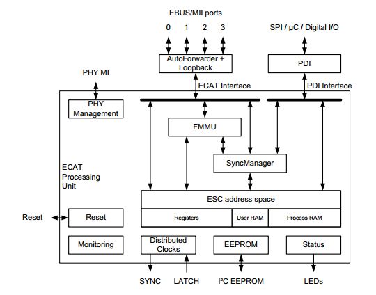
一般写配置参数都是通过Mailbox模式,而交换实时数据则是通过Buffered 模式。In both these modes, this data sharing is managed by what is known as the Sync Manager. In the case of buffered mode, the sync manager keeps buffers for the master and the slave to make sure there are not data collisions. Each sync manager can be configured for one of four modes: RX Mailbox - Mailbox receive to slave TX Mailbox - Mailbox transmit from slave RX Buffered - Buffered receive to slave TX Buffered - Buffered transmit from slave
On the ET1100 chip there are four Sync Managers, labeled 0 through 3. Although any Sync manager can be configured to behave in any way, by EtherCAT convention sync managers 0 and 1 should be configured for RX and TX mailbox mode, and 2 and 3 should be configured for RX and TX buffered mode.
Although from slave and master program’s perspective, the data being sent from a slave appears to be a chunk of memory that is the sync manager, all the data from all the slaves is actually placed into a single EtherCAT packet. The Fieldbus Memory Management Units (FMMUs) are the parts of the slave controller that are responsible for mapping memory from the Sync Managers into the EtherCAT frame. There has to be a FMMU associated with each sync manager so that the data from that sync manager is placed correctly into the EtherCAT frame. As with the Sync Manager the FMMU has to be configured with the direction a data direction, either input or output from the perspective of the slave.
Process Data Objects (PDOs)
As mentioned earlier, we are using the Buffered mode for our data communications. The sync managers essentially provide a shared memory interface between a master and a slave. This great but it doesn’t provide a way to define a communications protocol between a master and a slave. This problem is solved by Process Data Objects (PDOs). PDOs are a way of defining how data is packed into a buffered sync manager. The use of a standardized PDO description (as described in the ESI file) make it possible for any EtherCAT master stack to communicate with any slave without large amounts of customization.
Each Process Data Object is supposed to contain the information for a particular subsystem of the slave. A sync manager can have many PDOs and each PDO can contain more than one variable. To use and example from ATRIAS, each Medulla has one or more encoder PDOs, and each of those PDOs contain a variable for the encoder position and a timestamp variable containing the exact time when the reading was taken. This encapsulates everything you would need to know to use the data from the encoder.
All the PDOs are placed into the Sync Manager memory in the order that they have been defined in the ESI XML file. The size of the PDO is calculated based upon the sum of the sizes of the PDO elements as defined in the ESI file. Therefore, any one PDO element can be found in the Sync Manager memory based upon the order of PDOs in the ESI file, and the order and size of the elements of each PDO.
见图:
对于CoE,通过Ethercat来读写CANOpen对象字典,一般来说所有的对象字典(可以读写的)都可以通过 Mailbox 模式 ( Mailbox 模式支持很多协议,如 CoE, FoE等等 ) 来读写配置,Mailbox通常用于SDO,能够确保正确的数据传输;但是对于PDO,通过Mailbox的方式来读写就效率不高了(因为读写可能会阻塞),因此可以配置PDO mapping,将实时过程数据通过 Buffered Mode 来读写,这样就能够充分利用总线的资源提高系统的效率。
不过,不是所有的对象字典都能够映射成PDO,因此需要根据厂商的手册进行映射:
通常需要映射的PDO数据有:
Inputs
status_word
actual_position
actual_velocity
actual_torque
actual_mode
error_code (也可以不放在PDO中,通过SDO来读取)
Outputs
control_word
target_mode
target_position
target_velocity
target_torque
一个SOEM PDO mapping example:
也请查看文档https://download.csdn.net/download/gw569453350game/10970476
		ec_statecheck(0, EC_STATE_PRE_OP, EC_TIMEOUTSTATE);

        int wsum = 0;

        wsum += write8(1,0x6060,0,10); // Set mode of operation to CST

        wsum += write8 (1, 0x1C12, 0, 0);
        wsum += write8 (1, 0x1600, 0, 0);
        wsum += write32(1, 0x1600, 1, 0x60400010); // Control word
        wsum += write32(1, 0x1600, 2, 0x60710010); // Target torque
        wsum += write8 (1, 0x1600, 0, 2);
        wsum += write16(1, 0x1C12, 1, 0x1600);
        wsum += write8 (1, 0x1C12, 0, 1);

        wsum += write8 (1, 0x1C13, 0, 0);
        wsum += write8 (1, 0x1A00, 0, 0);
        wsum += write32(1, 0x1A00, 1, 0x60410010); // Status word
        wsum += write32(1, 0x1A00, 2, 0x60640020); // Position actual value
        wsum += write32(1, 0x1A00, 3, 0x606C0020); // Velocity actual value
        //wsum += write32(1, 0x1A00, 4, 0x60770010); // Torque actual value
        wsum += write8 (1, 0x1A00, 0, 3);
        wsum += write16(1, 0x1C13, 1, 0x1A00);
        wsum += write8 (1, 0x1C13, 0, 1);
关于 Working Counter(WKC) 和FMMU的寻址:
一个Ethercat帧数据可以包含多个Ethercat Datagram,而每一个 Ethercat Datagram都包含一个Working Counter.
一般多个电机驱动器,在所有slave进入OP后都是通过FMMU映射来使用 Ethercat Logic Addressing,将各个slave本地内存映射到一整个4G地址空间,这样就可以通过一个 Ethercat Datagram 来交换所有的Slave的数据,在这种情况下,该Ethercat Datagram的Working Counter就应该是所有slave的读写(读+1,写+1,读写+3)相加总和,也就只存在一个Working Counter值了。
https://download.csdn.net/download/gw569453350game/10976585
https://www.automation.com/pdf_articles/ETG_Diagnostics_with_EtherCAT_Part_1.pdf
关于 FMMU 逻辑地址映射,可参考这个链接:
http://www.manualsdir.com/manuals/757430/beckhoff-ethercat-technology-section-i.html?page=59