vivado+zedboard之流水灯
环境:win7 64
vivado 2013.2
开发板:zedboard version d
xc7z020clg484-1
串口软件:SecureCRT
问题:使用vivado进行zedboard开发,制作一个简单的流水灯程序以说明软硬件协同设计的方法、开发流程等。
正文:
本文将分为三个部分:
1. 使用Vivado IDE创建一个工程,并构建一个Zynq嵌入式处理系统
2. 在上述基础上,将完成后的硬件导入到SDK中进行软件设计。
3. 最后下载到ZedBoard上进行调试。
1. 使用Vivado IDE创建一个工程,并构建一个Zynq嵌入式处理系统。(vivado)
新建工程
在vivado中新建一个RTL工程,暂不添加文件,选择ZedBoard Zynq Evaluation and Development Kit version D器件,finish。
硬件设计
1. Create Block Design
2. Add IP->ZYNQ7 Processing System;Run Block Automation;
3. Add IP->AXI GPIO;AXI BRAM;Block Memory Generator;添加三个IP
对Block Memory Generator:Customize Block->Mode to BRAM Controller ;Memory Type to True Dual Port RAM
然后:连接 the Block Memory Generator to the AXI4 BRAM Controller

4. Run Connection Automation and then select /axi_gpio_1/s_axi
Run Connection Automation again, and the /axi_gpio_1/gpio; Select leds_8bits
Run Connection Automation again, and select the /axi_bram_ctrl_1/S_AXI

5. Change the range of the AXI BRAM Controller to 64K
6. File > Save Block Design
硬件处理
1. Tools >Validate Design
2. right-click the top-level subsystem design->Generate Output Products
3. right-click the top-level subsystem design->Create HDL Wrapper
4. Generate Bitstream;click Open Implemented Design
5. Open Block to invoke the IP integrator design
6. File ->Export Hardware for SDK;选择launch SDK

2. 在上述基础上,将完成后的硬件导入到SDK中进行软件设计。(SDK)
此时SDK已经自启动了。
1. File > New > Application Project

2. 选择一个空的模板:empty application
3. File > New > Source File
4. 编写Marquee.c
/*
 * Marquee.c
 *
 *  Created on: 2014-7-3
 *      Author: ZhouQiang
 */


#include "xparameters.h"		/* Peripheral parameters  */
#include "xgpio.h"				/* GPIO data struct and APIs */
#include "xil_printf.h"
#include "xil_cache.h"
#define GPIO_BITWIDTH	8		/* This is the width of the GPIO */
#define GPIO_DEVICE_ID  XPAR_AXI_GPIO_1_DEVICE_ID//device id
#define LED_DELAY     	10000000/* times delay*/
#define LED_MAX_BLINK	0x1		/* Number of times the LED Blinks */
#define LED_CHANNEL 	1		/* GPIO channel*/
#define printf xil_printf	/* A smaller footprint printf */
XGpio Gpio; /* The Instance of the GPIO Driver */
XGpio GpioOutput; /* The driver instance for GPIO Device configured as O/P */

int GpioMarquee (u16 DeviceId, u32 GpioWidth)
{
	volatile int Delay;
	u32 LedBit;
	u32 LedLoop;
	int Status;
	/*
	 * Initialize the GPIO driver so that it's ready to use,
	 * specify the device ID that is generated in xparameters.h
	 */
	 Status = XGpio_Initialize(&GpioOutput, DeviceId);
	if (Status != XST_SUCCESS)
	{
		return XST_FAILURE;
	 }
	//Set the direction for all signals to be outputs
	 XGpio_SetDataDirection(&GpioOutput, LED_CHANNEL, 0x0);
	// Set the GPIO outputs to low
	 XGpio_DiscreteWrite(&GpioOutput, LED_CHANNEL, 0x0);

	for (LedBit = 0x0; LedBit < GpioWidth; LedBit++)
	{
		for (LedLoop = 0; LedLoop < LED_MAX_BLINK; LedLoop++)
		{
			//Set the GPIO Output to High
			XGpio_DiscreteWrite(&GpioOutput, LED_CHANNEL,1 << LedBit);
			//Wait a small amount of time so the LED is visible
			for (Delay = 0; Delay < LED_DELAY;Delay++);
			//Clear the GPIO Output
			XGpio_DiscreteClear(&GpioOutput, LED_CHANNEL,1 << LedBit);
			// Wait a small amount of time so the LED is visible
			for (Delay = 0; Delay < LED_DELAY; Delay++);
		  }
	 }
	return XST_SUCCESS;
}
int main(void)
{//Application start
	/* loop forever*/
	int cnt=0;
	while(1)
	{
		u32 status;
		status = GpioMarquee (GPIO_DEVICE_ID,GPIO_BITWIDTH);
		if (status == 0)
		{
			printf("%d:SUCESS!.\r\n",cnt++);
			if(cnt>=1000)
				cnt=0;
		}
		else
			printf("FAILED.\r\n");
	}
	return XST_SUCCESS;
}
5. 控制台出现:'Finished building: Marquee.elf.size',说明已经编译好了。
3. 最后下载到ZedBoard上进行调试。
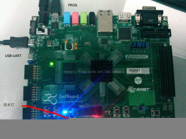
1. 将ZedBoard同PC机相连接,插上串口线与Jtag线,如果是第一次连接请等待一段时间,操作系统会自动安装所需的驱动。见最后图。需要用两个microUSB线连接,一个用于烧写程序,一个用于串口通信。
2. power on;使用SecureCRT等串口工具连接
3. Xilinx tools->Program FPGA将bit流写入FGPA中
4. 右键工程目录中的Marquee目录,选择Run As > Run Configurations;即可运行程序。
看到流水灯的效果,每次跑完一圈会打印:196:SUCESS!.的消息,数字为次数。
至此,关于流水灯的程序介绍完毕;关于vivado+SDK+Zedboard的开发流程介绍完毕;关于zedboard板下载和串口通信的方法也有介绍。分享出来,还请指教。