LQR与汽车横向动力学
LQR的另外一个维度是有限时间和无限时间。对于连续系统而言,有限时间和无限时间的主要区别就是黎卡提方程形式有所不同。对于离散系统而言,求解的推导方式上就会有一些变化。很多书籍或者资料都会讲到离散系统的后向推导方法。这种解法本质上属于基于动态规划(Dynamic Programming)的求解。
对于有些控制指标来说,其控制时间应该被认为是无限的。比如大家经常看到的倒立摆稳定问题,对于该系统来说保持摆不掉下来是一个长期指标。对于这种情况,就不应该使用动态规划的方式了,而是应该使用离散形式的无限时间算法。这里我不准备介绍离散系统的动态规划求解了,因为汽车横向动力学属于一个无限时间的控制问题。所以直接开始从连续系统说起LQR。
无限时间的连续LQR和离散LQR算法
首先,一个连续线性系统可以表示为:

而P矩阵是根据连续时间的代数Riccati方程求得的,其中Riccati方程如下:

具体的证明过程,这里就先略过了,最优化控制的书都会有。
至此,我们已经得到了连续系统的LQR的控制律,那么离散系统的LQR控制率呢?首先还是写出离散系统的系统方程:

前面的公式贴了一大堆,但是实际使用LQR中,其重点还是建模和参数。因为LQR的理论其实是非常成熟的,只要把模型参数传递进去,就可以计算出最优控制律。以动力学问题为例,其实建模主要体现在各种力学平衡方程的建立、状态变量的定义、损失函数中参数的选择(比如Q,R,N这些矩阵中参数的选择)。
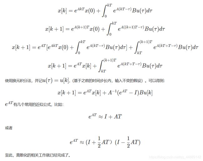
 我们假设输入uuu在每一个时间步长内,都是不变的。定义T为时间步长、x[k]为x(kT),则有如下变换:
 汽车的横向动力学建模
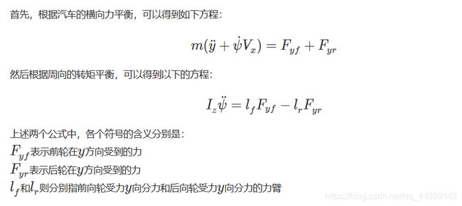
首先还是从汽车动力学出发吧!首先贴一张汽车横向动力学的示意图:

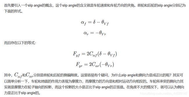
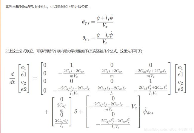
 接下来根据转角几何来分析动力学,首先还是贴一张转角的示意图:


 自动驾驶汽车的横向控制——基于Apollo的实现
apollo的横向控制代码主要实现在apollo/modules/control/controller/lat_controller.cc。
控制器初始化的代码在init函数里面:
Status LatController::Init(const ControlConf *control_conf) {
  if (!LoadControlConf(control_conf)) {
    AERROR << "failed to load control conf";
    return Status(ErrorCode::CONTROL_COMPUTE_ERROR,
                  "failed to load control_conf");
  }
  // Matrix init operations.
  const int matrix_size = basic_state_size_ + preview_window_;
  matrix_a_ = Matrix::Zero(basic_state_size_, basic_state_size_);
  matrix_ad_ = Matrix::Zero(basic_state_size_, basic_state_size_);
  matrix_adc_ = Matrix::Zero(matrix_size, matrix_size);

  matrix_a_(0, 1) = 1.0;
  matrix_a_(1, 2) = (cf_ + cr_) / mass_;
  matrix_a_(2, 3) = 1.0;
  matrix_a_(3, 2) = (lf_ * cf_ - lr_ * cr_) / iz_;

  matrix_a_coeff_ = Matrix::Zero(matrix_size, matrix_size);
  matrix_a_coeff_(1, 1) = -(cf_ + cr_) / mass_;
  matrix_a_coeff_(1, 3) = (lr_ * cr_ - lf_ * cf_) / mass_;
  matrix_a_coeff_(2, 3) = 1.0;
  matrix_a_coeff_(3, 1) = (lr_ * cr_ - lf_ * cf_) / iz_;
  matrix_a_coeff_(3, 3) = -1.0 * (lf_ * lf_ * cf_ + lr_ * lr_ * cr_) / iz_;

  matrix_b_ = Matrix::Zero(basic_state_size_, 1);
  matrix_bd_ = Matrix::Zero(basic_state_size_, 1);
  matrix_bdc_ = Matrix::Zero(matrix_size, 1);
  matrix_b_(1, 0) = cf_ / mass_;
  matrix_b_(3, 0) = lf_ * cf_ / iz_;
  matrix_bd_ = matrix_b_ * ts_;

  matrix_state_ = Matrix::Zero(matrix_size, 1);
  matrix_k_ = Matrix::Zero(1, matrix_size);
  matrix_r_ = Matrix::Identity(1, 1);
  matrix_q_ = Matrix::Zero(matrix_size, matrix_size);

  int q_param_size = control_conf->lat_controller_conf().matrix_q_size();
  if (matrix_size != q_param_size) {
    const auto error_msg =
        StrCat("lateral controller error: matrix_q size: ", q_param_size,
               " in parameter file not equal to matrix_size: ", matrix_size);
    AERROR << error_msg;
    return Status(ErrorCode::CONTROL_COMPUTE_ERROR, error_msg);
  }
  for (int i = 0; i < q_param_size; ++i) {
    matrix_q_(i, i) = control_conf->lat_controller_conf().matrix_q(i);
  }

  matrix_q_updated_ = matrix_q_;
  InitializeFilters(control_conf);
  auto &lat_controller_conf = control_conf->lat_controller_conf();
  LoadLatGainScheduler(lat_controller_conf);
  LogInitParameters();
  return Status::OK();
}
代码中的matrix_a_对应的就是状态矩阵A,matrix_a_coeff_是用来辅助更新matrix_a_的。而matrix_ad_就是离散模型的状态矩阵。对于控制矩阵B来说,命名规则也是类似的。matrix_adc_和matrix_bdc_就先忽略吧,默认配置下它们是等同于matrix_ad和matrix_bd_的。
在控制过程中,其实是有一个定时器不断调用控制器,让控制器计算出控制量,然后再发送给执行器,比如CAN总线上的执行单元。完成这个功能的函数就是如下这个函数:
Status LatController::ComputeControlCommand(
    const localization::LocalizationEstimate *localization,
    const canbus::Chassis *chassis,
    const planning::ADCTrajectory *planning_published_trajectory,
    ControlCommand *cmd) {
  // Update state = [Lateral Error, Lateral Error Rate, Heading Error, Heading
  // Error Rate, preview lateral error1 , preview lateral error2, ...]
  UpdateState(debug);
  UpdateMatrix();
  // Compound discrete matrix with road preview model
  UpdateMatrixCompound();
  // Add gain scheduler for higher speed steering
  if (FLAGS_enable_gain_scheduler) {
    matrix_q_updated_(0, 0) =
        matrix_q_(0, 0) *
        lat_err_interpolation_->Interpolate(
            VehicleStateProvider::instance()->linear_velocity());
    matrix_q_updated_(2, 2) =
        matrix_q_(2, 2) *
        heading_err_interpolation_->Interpolate(
            VehicleStateProvider::instance()->linear_velocity());
    common::math::SolveLQRProblem(matrix_adc_, matrix_bdc_, matrix_q_updated_,
                                  matrix_r_, lqr_eps_, lqr_max_iteration_,
                                  &matrix_k_);
  } else {
    common::math::SolveLQRProblem(matrix_adc_, matrix_bdc_, matrix_q_,
                                  matrix_r_, lqr_eps_, lqr_max_iteration_,
                                  &matrix_k_);
  }
  // feedback = - K * state
  // Convert vehicle steer angle from rad to degree and then to steer degree
  // then to 100% ratio
  const double steer_angle_feedback = -(matrix_k_ * matrix_state_)(0, 0) * 180 /
                                      M_PI * steer_ratio_ /
                                      steer_single_direction_max_degree_ * 100;
  const double steer_angle_feedforward = ComputeFeedForward(debug->curvature());
  // Clamp the steer angle to -100.0 to 100.0
  double steer_angle = common::math::Clamp(
      steer_angle_feedback + steer_angle_feedforward, -100.0, 100.0);

  if (VehicleStateProvider::instance()->linear_velocity() <
          FLAGS_lock_steer_speed &&
      VehicleStateProvider::instance()->gear() == canbus::Chassis::GEAR_DRIVE &&
      chassis->driving_mode() == canbus::Chassis::COMPLETE_AUTO_DRIVE) {
    steer_angle = pre_steer_angle_;
  }
  pre_steer_angle_ = steer_angle;
  cmd->set_steering_target(steer_angle);

  cmd->set_steering_rate(FLAGS_steer_angle_rate);
  return Status::OK();
}
代码被我精简了不少,可以很清晰地看到程序的脉络,首先算出观测值,然后更新动力学模型中各个个矩阵的参数,然后计算前向控制和反馈控制,最后把方向盘转角传递给控制命令cmd。这个流程大致就是这样,接下来我们看看矩阵更新的代码,体验一下LQR的离散化过程。其实就是updateMatrix函数了。
void LatController::UpdateMatrix() {
  const double v = std::max(VehicleStateProvider::instance()->linear_velocity(),
                            minimum_speed_protection_);
  matrix_a_(1, 1) = matrix_a_coeff_(1, 1) / v;
  matrix_a_(1, 3) = matrix_a_coeff_(1, 3) / v;
  matrix_a_(3, 1) = matrix_a_coeff_(3, 1) / v;
  matrix_a_(3, 3) = matrix_a_coeff_(3, 3) / v;
  Matrix matrix_i = Matrix::Identity(matrix_a_.cols(), matrix_a_.cols());
  matrix_ad_ = (matrix_i - ts_ * 0.5 * matrix_a_).inverse() *
               (matrix_i + ts_ * 0.5 * matrix_a_);
}
是不是感觉matrix_ad_的计算代码很眼熟,其实就是本文第一部分提到的近似计算公式。至此,LQR的理论与实践都算是分析了一遍~~~
参考文献:
【1】https://github.com/ApolloAuto/apollo
【2】Rajamani R. Vehicle Dynamics and Control[M] Second Edition
【3】https://en.wikipedia.org/wiki/Linear-quadratic_regulator
【4】https://en.wikipedia.org/wiki/Discretization#Approximations
转自:http://intheworld.win/2018/11/24/lqr%E4%B8%8E%E6%B1%BD%E8%BD%A6%E6%A8%AA%E5%90%91%E5%8A%A8%E5%8A%9B%E5%AD%A6/


