HTA0视觉抓取机器人源码解读
1 HTA0机器人简介
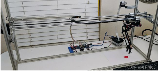
HTA0机器人英文名Horizontal Travel Robot Arm,是由fdx Labs实验室推出的开源机器人,机器人网站https://www.fdxlabs.com/products/horizontal-travel-robot-arm-hta0/,github地址https://github.com/pacogarcia3/hta0-horizontal-robot-arm。这是一个3自由度的机器人,配备有摄像头,可以实现视觉抓取。机器人长这个样子:
2 机器人底层部分软件
2.1 软件基本流程
HAT0底层软件在文件夹arduino_sketch文件夹下的arm_v3.ino文件中。主函数loop()函数中接收上位机发下来的数据,数据格式:
void loop() {
  // put your main code here, to run repeatedly:
  bool loop=true;

  recvWithStartEndMarkers();
  showNewData();
  //delay(5000);

  //data format  = <23,56,89,1,1,3456,3> {17}
  //X: 7.00 Y: 8.00 Z: 9.00 bool_move: 1.00 bool_open: 0.00 delay_ms: 10.00 move_type: 1.00

  //the bool_move controls if the arm moves linearly to the position or performs a pick/grab motions (move x first/y second etc)

  //<0,0,-9,1,1,1>

  if (newData==true && loop==true) {
    coordinate_move(XYZ_next[0],XYZ_next[1],XYZ_next[2],XYZ_next[3]);//机械臂跑到目的坐标
    servo_Open(XYZ_next[4]);//机械手张开或关闭
    delay(XYZ_next[5]);//延时
    newData=false;
    Serial.println("done");
  }

}
2.2 机械手姿态解算
图1
图2
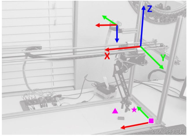
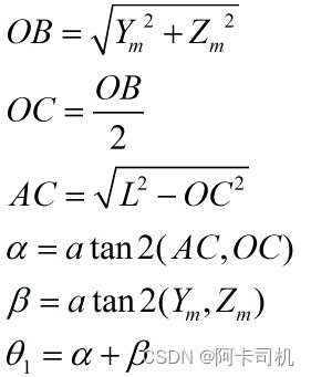
机械臂的坐标如图1所示。如图2,机械臂由2个转动关节组成,俩个臂长度都为L。末端的位置坐标(Ym,Zm)。则计算关节1角度θ 1有:
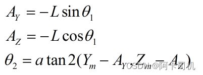
计算关节角θ 2:
函数void get_angles_from_yz(double y, double z)实现的就是计算俩个关节角的功能,并把结果存入angle_next[0]和angle_next[1]。
2.3 运动控制
实现运动控制的函数void coordinate_move(double xEnd, double yEnd, double zEnd, bool liftgrab_motion),x轴的步进电机直接由IO控制,Y轴和Z轴的步进电机都有Arduino的Servo模块控制。
void  coordinate_move(double xEnd, double yEnd, double zEnd, bool liftgrab_motion) {

  double xStart = XYZ_current[0];
  double yStart = XYZ_current[1];
  double zStart = XYZ_current[2];

  //Serial.println("/ Coord Move Start /");

  //calibrate stepper steps into cms (for x axis)

  double x_to_steps = STEPS_PER_CM[0];

  //identify if there is movement in the y Axis
  double zDelta = zEnd - zStart;
  //identify if there is movement in the z Axis
  double xDelta = xEnd - xStart;

  double x_stepper_steps = x_to_steps * abs(xDelta);

  if (xDelta != 0) {
    if (xDelta > 0) {
      stepper_advance(0, x_stepper_steps, 0);
    } else {
      stepper_advance(0, x_stepper_steps, 1);
    }
  }

  //the liftbrab_motion bool is equivalent to the bool_move paramter
  // controls if the arm moves linearly to the position or performs a pick/grab motions (move Y first/z second etc)


  if (liftgrab_motion == true) {
    if (zDelta < 0) {
      //arm is going to move down, move Y first

      // move arms in Y direction
      get_angles_from_yz(yEnd, zStart);
      twoarm_step_coordinate(angle_next[0], angle_next[1]);

      // move arms in Z direction
      get_angles_from_yz(yEnd, zEnd);
      twoarm_step_coordinate(angle_next[0], angle_next[1]);

    } else {
      //arm is moving up, perform Y movement first.

      // move arms in Z direction
      get_angles_from_yz(yStart, zEnd);
      twoarm_step_coordinate(angle_next[0], angle_next[1]);

      // move arms in Y direction
      get_angles_from_yz(yEnd, zEnd);
      twoarm_step_coordinate(angle_next[0], angle_next[1]);
    }

  } else {
    get_angles_from_yz(yEnd, zEnd);
    twoarm_step_coordinate(angle_next[0], angle_next[1]);
  }


  //Serial.println("/ Coord Move End /");

  //Serial.println("  ");
  //Serial.print(" xStart=  "); Serial.print(xStart); Serial.print(" yStart=  "); Serial.println(yStart);
  //Serial.print("Angle Top Arm="); Serial.print(angle_TopArm); Serial.print(" Angle Middle Arm=  "); Serial.println(angle_MiddleArm);
  //Serial.print("Angle Top Arm_next="); Serial.print(angle_TopArm_next); Serial.print(" Angle Middle Arm_next=  "); Serial.println(angle_MiddleArm_next);
  //Serial.print(" xEnd=  "); Serial.print(xEnd);   Serial.print(" yEnd=  "); Serial.println(yEnd);

  XYZ_current[0] = xEnd;
  XYZ_current[1] = yEnd;
  XYZ_current[2] = zEnd;
  XYZ_current[3] = liftgrab_motion;
}
3 机器人上位机软件
机器人上位机软件是用pyhon写的,包括以下文件:
main.py    //启动主程序运行
main_loop.py //主逻辑运行函数
commands_arduino.py //与下位机通信命令
camera_realworldxyz.py //图像识别接口,世界坐标计算接口
initial_perspective_calibration.py //准备透视变换的相关矩阵,保存到文件中
initial_camera_calibration.py //摄像头标定,并生成摄像头标定矩阵等参数矩阵,保存到文件中
image_recognition_singlecam.py //图像识别相关功能函数
3.1 上位机主函数逻辑
主函数就在main.py里面,用ImageDetection()开启主循环。它调用main_loop.py中的capturefromPiCamera()函数,不停的读取摄像头捕捉到的照片。在该函数中首先识别背景,然后再不停的捕捉图片,当识别到有物体时,计算出物体坐标XYZ,再通过pickanddrop(XYZ,arm)函数将物体抓取起来扔到箱子里。pickanddrop()函数完成抓物体的函数是move_and_pickup(),完成扔物体的函数是transport_and_drop()。这俩个函数最终都是调用move_untildone()函数来实现电机运动控制。move_untildone是根据通信格式向下位机串口发送位置消息来控制机械臂运动。
def move_untildone(self, inputarr):
        #data format  = <23,56,89,1,1,3456,3> {17}
        #X: 7.00 Y: 8.00 Z: 9.00 bool_move: 1.00 bool_open: 0.00 delay_ms: 10.00 move_type: 1.00

        #bool_move controls if the arm moves linearly to the position or coordinates y/z to pickup

        inputs="<"+str(inputarr[0])+","+str(inputarr[1])+","+str(inputarr[2])+","+str(inputarr[3])+","+str(inputarr[4])+","+str(inputarr[5])+">"
        inputs=inputs.encode("utf-8")

        self.ser.write(inputs)
        while True:
            str1=self.decodestr(self.ser.readline())
            print(str1),
            if str1=="done":
                break
3.2 相机透镜模型
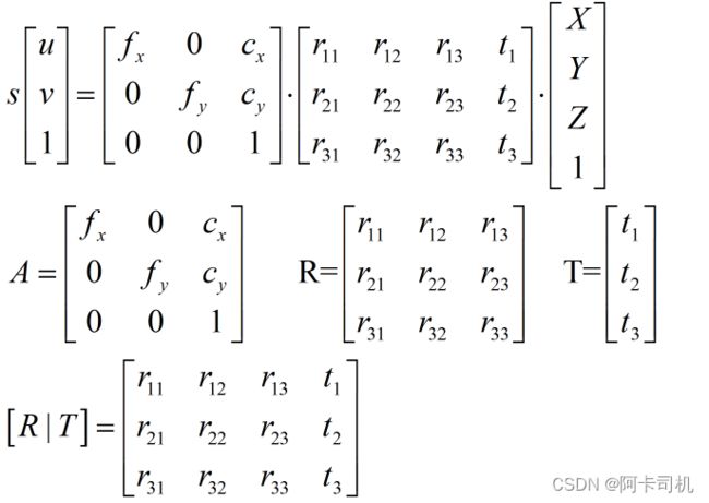
对于上图所示的相机成像系统,有相机透镜公式成立:
其中:u,v是相机坐标下的像素坐标
XYZ是世界坐标系下点的世界坐标
s是放大系数
矩阵A是相机标定矩阵,fx,fy是相机焦距,cx,cy是相机光心坐标
R是相机姿态矩阵,T是相机平移矩阵
如何求出以上矩阵参数,是initial_camera_calibration.py和initial_perspective_calibration.py文件的主要工作。
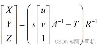
已知相机像素(u,v),求相机世界坐标的公式为:
3.3 相机标定求取标定矩阵A
相机标定请参考:https://docs.opencv.org/3.3.0/dc/dbb/tutorial_py_calibration.html
相机标定的步骤是:1 准备一个棋盘格大小已知的象棋棋盘 2 对棋盘不同角度进行拍照,得到多张图片 3 提取图像中的棋盘角点(所谓角点是指俩个棋盘格相交的顶点,所以象棋盘每行有7个角点,每列有7个角点,共有49个角点),根据真是角点坐标数组和提取的角点像素矩阵,输入到opencv的cv2.calibrateCamera()函数中求出标定矩阵。4 使用cv2.getOptimalNewCameraMatrix()函数求优化的标定矩阵。
本工程是存储在calibration_images中。本工程准备的象棋棋盘每个格子是2.5cm。求标定矩阵的代码都在initial_camera_calibration.py中,求出标定矩阵和畸变矩阵,并存入文件中。
3.4 求取其它参数矩阵
求取相机姿态矩阵需要用到opencv函数
ret, rvec1, tvec1=cv2.solvePnP(worldPoints,imagePoints,newcam_mtx,dist)参数1是点实际点在世界坐标系的坐标数组,参数2是点在相机平面的像素数组,参数3是相机的标定矩阵,参数4是相机的畸变矩阵。返回的rvec1是姿态矩阵对应的旋转向量,tvec1是平移矩阵。
准备世界坐标数组及其对应的像素数组
求得的标定矩阵为:
有光心像素坐标(cx,cy)=(628,342) ,因此可以在拍照的图中定位这个中心点:
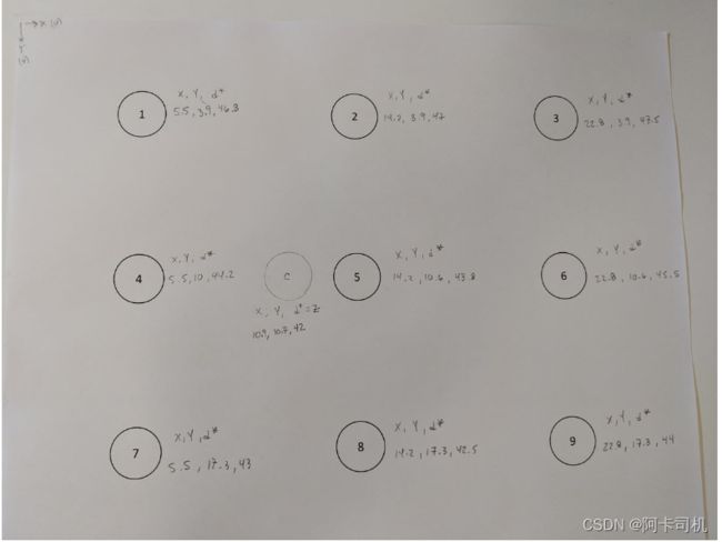
从摄像机镜头到这个点拉条绳子,这条绳子将与直面垂直,测得身子长度即为该点的Z轴坐标Zc,测点到纸边的距离可以得到Xc和Yc。对于其它9个圆心点,用类似方法可以测出(Xi,Yi,di),对应的Zi为:
通过图像识别可求出对应的图像坐标(Cxi,Cyi),最后求出的坐标为:
total_points_used=10

X_center=10.9
Y_center=10.7
Z_center=43.4
worldPoints=np.array([[X_center,Y_center,Z_center],
                       [5.5,3.9,46.8],
                       [14.2,3.9,47.0],
                       [22.8,3.9,47.4],
                       [5.5,10.6,44.2],
                       [14.2,10.6,43.8],
                       [22.8,10.6,44.8],
                       [5.5,17.3,43],
                       [14.2,17.3,42.5],
                       [22.8,17.3,44.4]], dtype=np.float32)

#MANUALLY INPUT THE DETECTED IMAGE COORDINATES HERE

#[u,v] center + 9 Image points
imagePoints=np.array([[cx,cy],
                       [502,185],
                       [700,197],
                       [894,208],
                       [491,331],
                       [695,342],
                       [896,353],
                       [478,487],
                       [691,497],
                       [900,508]], dtype=np.float32)


#FOR REAL WORLD POINTS, CALCULATE Z from d*

for i in range(1,total_points_used):
    #start from 1, given for center Z=d*
    #to center of camera
    wX=worldPoints[i,0]-X_center
    wY=worldPoints[i,1]-Y_center
    wd=worldPoints[i,2]

    d1=np.sqrt(np.square(wX)+np.square(wY))
    wZ=np.sqrt(np.square(wd)-np.square(d1))
    worldPoints[i,2]=wZ

print(worldPoints)
姿态矩阵和平移矩阵求取
然后可以求出姿态矩阵和平移矩阵:
#load camera calibration
savedir="camera_data/"
cam_mtx=np.load(savedir+'cam_mtx.npy')
dist=np.load(savedir+'dist.npy')
newcam_mtx=np.load(savedir+'newcam_mtx.npy')
roi=np.load(savedir+'roi.npy')


ret, rvec1, tvec1=cv2.solvePnP(worldPoints,imagePoints,newcam_mtx,dist)
if writeValues==True: np.save(savedir+'rvec1.npy', rvec1)
if writeValues==True: np.save(savedir+'tvec1.npy', tvec1)

R_mtx, jac=cv2.Rodrigues(rvec1) #rvec1是1*3向量,用Rodrigues函数求3*3姿态矩阵
if writeValues==True: np.save(savedir+'R_mtx.npy', R_mtx)

Rt=np.column_stack((R_mtx,tvec1))  #Rt=R|t,3*4矩阵
if writeValues==True: np.save(savedir+'Rt.npy', Rt)

#P_mtx = A*Rt
P_mtx=newcam_mtx.dot(Rt)
if writeValues==True: np.save(savedir+'P_mtx.npy', P_mtx)
放大系数s的计算
s_arr=np.array([0], dtype=np.float32)
s_describe=np.array([0,0,0,0,0,0,0,0,0,0],dtype=np.float32)

for i in range(0,total_points_used):
    print("=======POINT # " + str(i) +" =========================")

    print("Forward: From World Points, Find Image Pixel")
    XYZ1=np.array([[worldPoints[i,0],worldPoints[i,1],worldPoints[i,2],1]], dtype=np.float32)
    XYZ1=XYZ1.T
    print("{{-- XYZ1")
    print(XYZ1)
    suv1=P_mtx.dot(XYZ1)
    print("//-- suv1")
    print(suv1)
    s=suv1[2,0]
    uv1=suv1/s
    print(">==> uv1 - Image Points")
    print(uv1)
    print(">==> s - Scaling Factor")
    print(s)
    s_arr=np.array([s/total_points_used+s_arr[0]], dtype=np.float32)
    s_describe[i]=s
    if writeValues==True: np.save(savedir+'s_arr.npy', s_arr)

    print("Solve: From Image Pixels, find World Points")

    uv_1=np.array([[imagePoints[i,0],imagePoints[i,1],1]], dtype=np.float32)
    uv_1=uv_1.T
    print(">==> uv1")
    print(uv_1)
    suv_1=s*uv_1
    print("//-- suv1")
    print(suv_1)

    print("get camera coordinates, multiply by inverse Camera Matrix, subtract tvec1")
    xyz_c=inverse_newcam_mtx.dot(suv_1)
    xyz_c=xyz_c-tvec1
    print("      xyz_c")
    inverse_R_mtx = np.linalg.inv(R_mtx)
    XYZ=inverse_R_mtx.dot(xyz_c)
    print("{{-- XYZ")
    print(XYZ)

    if calculatefromCam==True:
        cXYZ=cameraXYZ.calculate_XYZ(imagePoints[i,0],imagePoints[i,1])
        print("camXYZ")
        print(cXYZ)
3.5 待抓取物体的识别
首先识别出物体轮廓:
def detectObjects(self, image, bg_img,externalContours=True):

        img=image.copy()
        background_img=bg_img.copy()


        # Process Image Difference
        diff=self.calculateDifference_Otsu(img,background_img)

        # / Find the Contours
        # use RETR_EXTERNAL for only outer contours... use RETR_TREE for all the hierarchy
        if externalContours==True:
            contours_detected, hierarchy = cv2.findContours(diff, cv2.RETR_EXTERNAL,cv2.CHAIN_APPROX_SIMPLE)
        else:
            contours_detected, hierarchy = cv2.findContours(diff, cv2.RETR_TREE,cv2.CHAIN_APPROX_SIMPLE)

        #calculate key variables
        height, width, channels = img.shape

        # /// identify the VALID Contours
        contours_validindex= self.identify_validcontours(contours_detected,height,width)
        obj_count=len(contours_validindex)
        self.printStatus("valid contours "+ str(obj_count))

        return obj_count, contours_detected, contours_validindex
然后根据轮廓计算出轮廓中心图像坐标:
def detectionOutput(self, image, obj_count, validcontours, diff_contours):

        img_output=image.copy()

        detected_points=[]

        if (len(validcontours)>0):
            for i in range(0,len(validcontours)):
                cnt=diff_contours[validcontours[i]]

                #get rectangle detected_points
                x,y,w,h=cv2.boundingRect(cnt)

                #get centroid
                M=cv2.moments(cnt)
                cx=int(M['m10']/M['m00'])
                cy=int(M['m01']/M['m00'])

                self.printStatus("point number "+str(i))
                self.printStatus(str(cx)+", "+str(y))
                self.printStatus("x: "+str(x)+" y: "+str(y)+" w: "+str(w)+" h: "+str(h))

                #draw retangle
                cv2.rectangle(img_output,(x,y),(x+w,y+h),(0,255,0),2)
                #draw center
                cv2.circle(img_output,(cx,cy),3,(0,255,0),2)

                if self.PRINT_IMG_LABELS ==True:

                    #image,text,font,bottomleftconrner,fontscale,fontcolor,linetype
                    cv2.putText(img_output,"Point "+str(i),(x-w,y+h),cv2.FONT_HERSHEY_SIMPLEX,0.5,(255,0,0),1)
                    cv2.putText(img_output,"cx,cy: "+str(self.truncate(cx,2))+","+str(self.truncate(cy,2)),(x-w,y+h+9),cv2.FONT_HERSHEY_SIMPLEX,0.5,(255,0,0),1)

                points=[x,y,w,h,cx,cy]
                detected_points.append(points)

        if (obj_count>1 or len(validcontours)==0):
            self.previewImage("Multiple Objects Detected",img_output)
            one_object=False
        else:
            self.previewImage("One Objects Detected",img_output)
            one_object=True


        return obj_count, detected_points, img_output
组合成物体识别函数:
def run_detection(self,img,bg,testRun=False):

        obj_count, contours_detected, contours_validindex=self.detectObjects(img,bg)

        obj_count, detected_points, img_output=self.detectionOutput(img,obj_count,contours_validindex,contours_detected)

        return obj_count, detected_points, img_output
3.6 根据图像坐标计算世界坐标
camera_realworldxyz.py中的calculate_XYZ(self,u,v)函数是按照3.2节中的求相机世界坐标公式来计算世界坐标:
def calculate_XYZ(self,u,v):

        #Solve: From Image Pixels, find World Points

        uv_1=np.array([[u,v,1]], dtype=np.float32)
        uv_1=uv_1.T
        suv_1=self.scalingfactor*uv_1
        xyz_c=self.inverse_newcam_mtx.dot(suv_1)
        xyz_c=xyz_c-self.tvec1
        XYZ=self.inverse_R_mtx.dot(xyz_c)

        return XYZ
然后再detect_xyz函数中根据识别到的轮廓坐标计算物体世界坐标:
def detect_xyz(self,image,calcXYZ=True,calcarea=False):

        image_src=image.copy()

        #if calcXYZ==True:
        #    img= self.undistort_image(image_src)
        #    bg = self.bg_undst
        #else:
        img=image_src
        bg=self.bg

        XYZ=[]
        #self.previewImage("capture image",img_undst)
        #self.previewImage("bg image",self.bg_undst)
        obj_count, detected_points, img_output=self.imageRec.run_detection(img,self.bg)

        if (obj_count>0):

            for i in range(0,obj_count):
                x=detected_points[i][0]
                y=detected_points[i][1]
                w=detected_points[i][2]
                h=detected_points[i][3]
                cx=detected_points[i][4]
                cy=detected_points[i][5]

                cv2.rectangle(img,(x,y),(x+w,y+h),(0,255,0),2)

                #draw center
                cv2.circle(img,(cx,cy),3,(0,255,0),2)


                cv2.putText(img,"cx,cy: "+str(self.truncate(cx,2))+","+str(self.truncate(cy,2)),(x,y+h+28),cv2.FONT_HERSHEY_SIMPLEX,0.5,(0,255,0),2)
                if calcXYZ==True:
                    XYZ.append(self.calculate_XYZ(cx,cy))
                    cv2.putText(img,"X,Y: "+str(self.truncate(XYZ[i][0],2))+","+str(self.truncate(XYZ[i][1],2)),(x,y+h+14),cv2.FONT_HERSHEY_SIMPLEX,0.5,(0,255,0),2)
                if calcarea==True:
                    cv2.putText(img,"area: "+str(self.truncate(w*h,2)),(x,y-12),cv2.FONT_HERSHEY_SIMPLEX,0.5,(0,255,0),2)

        return img, XYZ