Kinect实现简单的三维重建
Kinect想必大家已经很熟悉了,最近基于Kinect的创意应用更是呈井喷状态啊!看到很多国外大牛用Kinect做三维重建,其中最著名的要数来自微软研究院的Kinect Fusion了,可以看看下面这个视频http://v.ku6.com/show/7q2Sa__pa4-rWcAVtB3Xuw...html,或者http://v.youku.com/v_show/id_XNDcxOTg3MzUy.html。
可惜Kinect Fusion是不开源的,不过PCL实现了一个差不多的开源版本,http://www.pointclouds.org/。有兴趣同时电脑配置高的朋友可以研究一下。
最近比较闲,有一点手痒,想自己做一个三维重建,不过肯定不会像Kinect Fusion那么强大,只是自己练练手、玩玩而已。代码在最后有下载。
1. 获取Kinect深度图:
首先我使用微软官方的Kinect SDK来控制Kinect,三维绘图我选用了OpenFrameworks。OpenFrameworks(以后简称OF)是一个开源的公共基础库,将很多常用的库统一到了一起,比如OpenGL,OpenCV,Boost等等,而且有大量的第三方扩展库,使用非常方便。具体可见http://www.openframeworks.cc/。
在一切开始之前,我们需要对OpenGL和三维场景做一些设置:
void testApp::setup(){
	//Do some environment settings.
	ofSetVerticalSync(true);
	ofSetWindowShape(640,480);
	ofBackground(0,0,0);

	//Turn on depth test for OpenGL.
	glEnable(GL_DEPTH_TEST);
	glDepthFunc(GL_LEQUAL);
	glShadeModel(GL_SMOOTH);

	//Put a camera in the scene.
	m_camera.setDistance(3);
	m_camera.setNearClip(0.1f);

	//Turn on the light.
	m_light.enable();

	//Allocate memory to store point cloud and normals.
	m_cloud_map.Resize(DEPTH_IMAGE_WIDTH,DEPTH_IMAGE_HEIGHT);
	m_normal_map.Resize(DEPTH_IMAGE_WIDTH,DEPTH_IMAGE_HEIGHT);
	//Initialize Kinect.
	InitNui();
}
OF是使用OpenGL进行绘图的,所以可以直接使用OpenGL中的函数(以gl开头),为了方便,OF还自己封装了一些常用函数(以of开头)。在上面代码的最后有一个InitNui()函数,在那里面我们会对Kinect进行初始化:
void testApp::InitNui()
{
	m_init_succeeded = false;
	m_nui = NULL;

	int count = 0;
	HRESULT hr;

	hr = NuiGetSensorCount(&count);
	if (count <= 0)
	{
		cout<<"No kinect sensor was found!!"<NuiInitialize(NUI_INITIALIZE_FLAG_USES_DEPTH);

	if (FAILED(hr))
	{
		cout<<"Initialize Kinect Failed!!"<NuiImageStreamOpen(NUI_IMAGE_TYPE_DEPTH,NUI_IMAGE_RESOLUTION_320x240,0,2,NULL,&m_depth_stream);
	if (FAILED(hr))
	{
		cout<<"Open Streams Failed!!"<NuiShutdown();
			m_nui->Release();
			m_nui = NULL;
		}
	}
}
接下来我们需要将每一帧的深度信息保存到我们自己的buffer中,专门写一个函数来做这件事情:
bool testApp::UpdateDepthFrame()
{
	if (!m_init_succeeded)return false;

	HRESULT hr;
	NUI_IMAGE_FRAME image_frame = {0};
	NUI_LOCKED_RECT locked_rect = {0};

	hr = m_nui->NuiImageStreamGetNextFrame(m_depth_stream,0,&image_frame);

	//If there's no new frame, we will return immediately.
	if (SUCCEEDED(hr))
	{
		hr = image_frame.pFrameTexture->LockRect(0,&locked_rect,NULL,0);
		if (SUCCEEDED(hr))
		{
			//Copy depth data to our own buffer.
			memcpy(m_depth_buffer,locked_rect.pBits,locked_rect.size);

			image_frame.pFrameTexture->UnlockRect(0);
		}
		//Release frame.
		m_nui->NuiImageStreamReleaseFrame(m_depth_stream,&image_frame);
	}

	if (SUCCEEDED(hr))return true;

	return false;
}
通过上面几步,我们已经可以拿到一幅深度图了。在OF中,每一帧更新时,update()函数都会被调用,我们可以把所有需要适时更新的代码都写在里面:
void testApp::update(){

	//Get a new depth frame from Kinect.
	m_new_depth = UpdateDepthFrame();

	if (m_new_depth)
	{
		Mat depth_frame = Mat(DEPTH_IMAGE_HEIGHT,DEPTH_IMAGE_WIDTH,CV_16UC1,m_depth_buffer);
 		imshow("Depth Frame", depth_frame);
  }
}
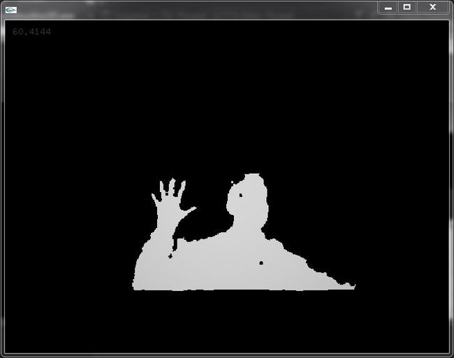
现在编译并运行程序,我们可以看到通过OpenCV画出来的深度图:
但你会发现,这样的深度图具有很多小孔和噪点,边缘也不平滑。因此要对图像进行滤波,为了使边缘不被模糊掉,这里最好使用中值滤波。修改一下上面的update()函数,使用5x5的窗口进行中值滤波:
void testApp::update(){

	//Get a new depth frame from Kinect.
	m_new_depth = UpdateDepthFrame();

	if (m_new_depth)
	{
		Mat smoothed_depth = Mat(DEPTH_IMAGE_HEIGHT,DEPTH_IMAGE_WIDTH,CV_16UC1,m_depth_buffer);
		medianBlur(smoothed_depth,smoothed_depth,5);
		imshow("Depth Frame", smoothed_depth);
	}
}
再次运行程序,得到的深度图就变成下面这样了,感觉好了很多!!
2. 通过深度图得到点云:
为了得到点云,我专门写了一个类来完成这一操作。这个类不仅会根据深度图计算点云,还会将得到的点云以矩阵的形式存放起来,矩阵中每一个元素代表一个点,同时对应深度图中具有相同行列坐标的像素。而计算点云的方法,Kinect SDK自身有提供,即NuiTransformDepthImageToSkeleton()函数,具体用法可看官方文档。
下面是这个类中生成点云的代码:
void PointCloudMap::Create(Mat& depth_image,USHORT max_depth,float scale)
{
	USHORT* depth_line = (USHORT*)depth_image.data;
	UINT stride = depth_image.step1();

	//m_points is the place where we store the whole point cloud.
	ofVec3f* points_line = m_points;
	Vector4 vec;
	for (DWORD y = 0; y < m_height; y++)
	{
		for (DWORD x = 0; x < m_width; x++)
		{
			ofVec3f point(0);
			USHORT real_depth = (depth_line[x] >> 3);
			if (real_depth >= 800 && real_depth < max_depth)
			{
				//For each pixel in the depth image, we calculate its space coordinates.
				vec = NuiTransformDepthImageToSkeleton(
					x,
					y,
					depth_line[x]
				);

				//Save the point with a scale.
				point.x = vec.x*scale;
				point.y = vec.y*scale;
				point.z = -vec.z*scale;
			}

			points_line[x] = point;
		}
		depth_line += stride;
		points_line += m_width;
	}
}
拿到点云后,我们可以考虑对点云进行三角化了。一提到三角化,很多人脑海中的第一印象是复杂、计算量大等等,我个人也是这样。但是,Kinect返回的点云是结构化的,并不是无序点云,也就是说每一个点在空间中与其他点的相互关系我们是知道的,因此可以用一些简单的方法来实现三角化,虽然这样的三角化结果不是最优的,但是简单快速,60fps毫无压力。
首先,我们的点云是存放在一个矩阵中的,而且矩阵的大小与深度图完全一样(行x列),因此我们将点云视为一幅图,每一个像素存放的是点的空间坐标。我们可以像遍历一般图像的像素一样遍历点云图,从而得到空间中某一点的所有相邻点。然后,我们使用OpenGL的连线功能,每画一个点就与它之前的两个点连成一个三角面。
如下图,点旁边的序号是画点的顺序:
这样我们就可以一行一行的将点云三角化,但注意当一行结束时,要让OpenGL停止连线,否则这一行最后的点会和下一行第一个点连在一起。
以上过程我直接写在了主程序的draw方法中,OF在每一帧调用完update方法后,就会调用draw方法:
void testApp::draw(){

	if (!m_init_succeeded)return;

	m_camera.begin();

	ofVec3f* points_line = m_cloud_map.m_points;
	ofVec3f* points_next_line = m_cloud_map.m_points + DEPTH_IMAGE_WIDTH;

	bool mesh_break = true;

	for (int y = 0; y < m_cloud_map.m_height - 1; y++)
	{
		for (int x = 0; x < m_cloud_map.m_width; x++)
		{
			ofVec3f& space_point1 = points_line[x];
			ofVec3f& space_point2 = points_next_line[x];

			if (abs(space_point1.z) <= FLT_EPSILON*POINT_CLOUD_SCALE ||
				abs(space_point2.z) <= FLT_EPSILON*POINT_CLOUD_SCALE)
			{
				if (!mesh_break)
				{
					//If there's no point here, the mesh should break.
					mesh_break = true;
					glEnd();
				}
				continue;
			}

			if (mesh_break)
			{
				//Start connecting points to form mesh.
				glBegin(GL_TRIANGLE_STRIP);
				mesh_break = false;
			}

			//Draw the point and set its normal.
			glColor3f(0.7,0.7,0.7);
			glVertex3f(space_point1.x,space_point1.y,space_point1.z);

			//Draw the point below the prior one to form a triangle.
			glColor3f(0.7,0.7,0.7);
			glVertex3f(space_point2.x,space_point2.y,space_point2.z);
		}
		if (!mesh_break)
		{
			//At the end of the line, we break the mesh.
			glEnd();
			mesh_break = true;
		}
		points_line += DEPTH_IMAGE_WIDTH;
		points_next_line += DEPTH_IMAGE_WIDTH;
	}

	m_camera.end();

	//Draw frame rate for fun!
	ofSetColor(255);
	ofDrawBitmapString(ofToString(ofGetFrameRate()),10,20);
}
再次编译并运行程序,在OF的窗口中,我们会看到如下结果:
怎么看起来是一张平面图,一点3D感觉都没有,呵呵~~因为我们还没有给顶点设置法向。OpenGL会根据顶点法线来计算该点的光照,如果没有法线,光照是失效的,也就是我们看到的白茫茫一片。
3. 计算顶点法向
法线的计算可以非常简单,比如对每一个点,取和它相邻的两个点组成三角形,计算这个三角形的法向,即作为该点的法向。但这种方法太不精确了,而且其中一个点的坐标稍有变化,就会影响最终法线的方向,光照效果会很不稳定。
我打算考虑一个点周围所有的点,并使用最小二乘法来拟合一个最佳平面,这个平面的法向即为该点的法向。
我们希望该点包括周围的领点到这个平面的距离之平方和最小,即使下式最小:
其中a,b,c是决定这个平面的参数,也就是这个平面的法矢量(a,b,c)。x,y,z是点的坐标。为了求出适合的abc值,分别对这三个变量求偏导:

要求最小值,就要使下面三式成立:
这样我们就得到一个关于a,b,c的三元一次线性方程组,表示为矩阵形式即如下:
根据Cramer法则,这个方程组的解可以表示为:
其中:
计算这些行列式的值后,就可解出a,b,c。
但是这里要注意,使用Cramer法则时,D不能为零,也就是说我们所期望的平面不能过原点。而过原点这种事情是很可能发生的,这时我们怎么办呢?
当平面过原点时,上面的三元一次方程组可简化为一个齐次方程组:
若上面系数矩阵的每一行所构成的向量共面但不共线,则a,b,c是有唯一解的,而其他情况下,只有零阶或无穷多个解。后者在实际应用中一般是不会出现的。因此我们只考虑前一种情况。这种情况的解,就是三个行向量所在面的法线。因此我们将这三个行向量两两作叉积(外积),得到三个垂直于该面的法线,取模最大的一个作为我们的解。
现在考虑什么点可以作为所求点的领点,由于点云是一幅图,我们可以借鉴二维图像滤波器的思想,将所求点周围的8领域点作为领点。(图画得丑,还请谅解):
但是我们的点是有深度的,所以还需对以上领域点判断一下深度,只有某一点的深度与中心点的深度接近时,才能真正当做领点。
现在还有最后一个问题,通过上面的方法算出来的法线方向是不定的(有可能是你想要的法向的反方向),因此我们还需要一个方法让所有法线的朝向一致,我这里就简单的选择了朝向摄像机。
将上面的所有方法写在了一个类中,这个类根据点云图计算法线,并像点云图一样将所有法线保存为一副法线图。下面是计算法线和调整朝向的代码:
void NormalsMap::Create(PointCloudMap& point_cloud, float max_distance)//创建一副法线图
{
	if (point_cloud.m_height != m_height ||
		point_cloud.m_width != m_width)
		throw exception("NormalsMap has different size width the PointCloudMap");

	ofVec3f* points_line0 = point_cloud.m_points;
	ofVec3f* points_line1 = points_line0 + m_width;
	ofVec3f* points_line2 = points_line1 + m_width;

	ofVec3f* norms_line = m_normals + m_width;
	vector neighbors;

	int y_line0 = 0;
	int y_line1 = y_line0 + m_width;
	int y_line2 = y_line1 + m_width;

	for (int y = 1; y < m_height - 1; y++)
	{
		for (int x = 1; x < m_width - 1; x++)
		{
			neighbors.clear();
			norms_line[x] = ofVec3f(0);
			if (points_line1[x].z == 0)continue;

			neighbors.push_back(points_line1[x]);
			//Add all neighbor points to the vector.
			if (IsNeighbor(points_line0[x-1],points_line1[x],max_distance))
			{
				neighbors.push_back(points_line0[x-1]);
			}
			if (IsNeighbor(points_line0[x],points_line1[x],max_distance))
			{
				neighbors.push_back(points_line0[x]);
			}
			if (IsNeighbor(points_line0[x+1],points_line1[x],max_distance))
			{
				neighbors.push_back(points_line0[x+1]);
			}

			if (IsNeighbor(points_line1[x-1],points_line1[x],max_distance))
			{
				neighbors.push_back(points_line1[x-1]);
			}
			if (IsNeighbor(points_line1[x+1],points_line1[x],max_distance))
			{
				neighbors.push_back(points_line1[x+1]);
			}

			if (IsNeighbor(points_line2[x-1],points_line1[x],max_distance))
			{
				neighbors.push_back(points_line2[x-1]);
			}
			if (IsNeighbor(points_line2[x],points_line1[x],max_distance))
			{
				neighbors.push_back(points_line2[x]);
			}
			if (IsNeighbor(points_line2[x+1],points_line1[x],max_distance))
			{
				neighbors.push_back(points_line2[x+1]);
			}

			if (neighbors.size() < 3)continue;//Too small to identify a plane.

			norms_line[x] = EstimateNormal(neighbors);
		}
		points_line0 += m_width;
		points_line1 += m_width;
		points_line2 += m_width;
		norms_line += m_width;

		y_line0 += m_width;
		y_line1 += m_width;
		y_line2 += m_width;
	}
}

inline bool NormalsMap::IsNeighbor(ofVec3f& dst, ofVec3f& ori, float max_distance)//判断是否是领点
{
	if (abs(dst.z - ori.z) < max_distance)
		return true;

	return false;
}

ofVec3f NormalsMap::EstimateNormal(vector& points)//使用最小二乘法计算法线
{
	ofVec3f normal(0);

	float x = 0, y = 0, z = 0;
	float x2 = 0, y2 = 0, z2 = 0;
	float xy = 0, xz = 0, yz = 0;
	for (int i = 0; i < points.size(); i++)
	{
		float cx = points[i].x;
		float cy = points[i].y;
		float cz = points[i].z;

		x += cx; y += cy; z += cz;
		x2 += cx*cx; y2 += cy*cy; z2 += cz*cz;
		xy += cx*cy; xz += cx*cz; yz += cy*cz;
	}

	float D = x2*y2*z2 + 2*xy*xz*yz - x2*yz*yz - y2*xz*xz - z2*xy*xy;
	if (abs(D) >= FLT_EPSILON)
	{
		//Use least squares technique to get the best normal.
		float Da = x*(yz*yz - y2*z2) - y*(yz*xz - z2*xy) + z*(y2*xz - xy*yz);
		float Db = x2*(z*yz - y*z2) - xy*(z*xz - x*z2) + xz*(y*xz - x*yz);
		float Dc = x2*(y*yz - z*y2) - xy*(x*yz - z*xy) + xz*(x*y2 - y*xy);

		normal.x = Da/D;
		normal.y = Db/D;
		normal.z = Dc/D;

		normal.normalize();
	}
	else
	{
		/*D == 0, it means some axes(x,y or z) are on the normal plane.
		We need another way to calculate normal vector.*/

		ofVec3f row0(x2,xy,xz);
		ofVec3f row1(xy,y2,yz);
		ofVec3f row2(xz,yz,z2);

		ofVec3f vec1 = row0.getCrossed(row1);
		ofVec3f vec2 = row0.getCrossed(row2);
		ofVec3f vec3 = row1.getCrossed(row2);

		float len1 = vec1.lengthSquared();
		float len2 = vec2.lengthSquared();
		float len3 = vec3.lengthSquared();

		if (len1 >= len2 && len1 >= len3)
			normal = vec1 / sqrt(len1);
		else if (len2 >= len1 && len2 >= len3)
			normal = vec2 / sqrt(len2);
		else
			normal = vec3 / sqrt(len3);
	}

	return normal;
}

void NormalsMap::FlipNormalsToVector(ofVec3f main_vector)//调整法线朝向,是其全部指向main_vector方向
{
	ofVec3f* normal = m_normals;
	for (int i = 0; i < m_width*m_height; i++)
	{
		if ((*normal).dot(main_vector) < 0)
			(*normal) *= -1;

		normal++;
	}
}
4. 全部放在一起:
将以上全部放在一起,并修改一下我们的draw函数,以使其设置顶点的法向:
void testApp::draw(){

	if (!m_init_succeeded)return;

	m_camera.begin();

	ofVec3f* points_line = m_cloud_map.m_points;
	ofVec3f* points_next_line = m_cloud_map.m_points + DEPTH_IMAGE_WIDTH;
	ofVec3f* normals_line = m_normal_map.m_normals;

	bool mesh_break = true;

	for (int y = 0; y < m_cloud_map.m_height - 1; y++)
	{
		for (int x = 0; x < m_cloud_map.m_width; x++)
		{
			ofVec3f& space_point1 = points_line[x];
			ofVec3f& space_point2 = points_next_line[x];

			if (abs(space_point1.z) <= FLT_EPSILON*POINT_CLOUD_SCALE ||
				abs(space_point2.z) <= FLT_EPSILON*POINT_CLOUD_SCALE)
			{
				if (!mesh_break)
				{
					//If there's no point here, the mesh should break.
					mesh_break = true;
					glEnd();
				}
				continue;
			}

			if (mesh_break)
			{
				//Start connecting points to form mesh.
				glBegin(GL_TRIANGLE_STRIP);
				mesh_break = false;
			}

			//Draw the point and set its normal.
			glColor3f(0.8,0.8,0.8);
			glNormal3f(normals_line[x].x,normals_line[x].y,normals_line[x].z);
			glVertex3f(space_point1.x,space_point1.y,space_point1.z);

			//Draw the point below the prior one to form a triangle.
			glColor3f(0.8,0.8,0.8);
			glVertex3f(space_point2.x,space_point2.y,space_point2.z);
		}
		if (!mesh_break)
		{
			//We break the mesh at the end of the line,.
			glEnd();
			mesh_break = true;
		}
		points_line += DEPTH_IMAGE_WIDTH;
		points_next_line += DEPTH_IMAGE_WIDTH;
		normals_line += DEPTH_IMAGE_WIDTH;
	}

	m_camera.end();

	//Draw frame rate for fun!
	ofSetColor(255);
	ofDrawBitmapString(ofToString(ofGetFrameRate()),10,20);
}
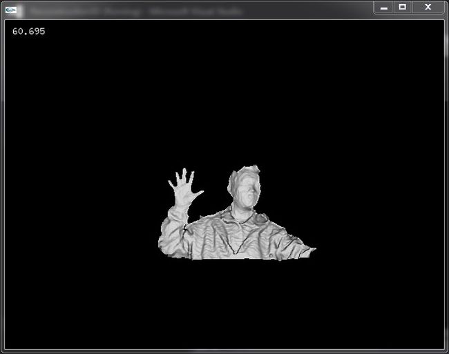
最后编译运行,我们的目标就达到了!!!!
作为一个自娱自乐的小程序,感觉还不错吧!!!注意看左上角的帧率,60fps妥妥的。
小结:
做这个完全是为了学习和兴趣,不要说我是重复造轮子啊。写这个程序复习了很多线性代数的知识,温故而知新,感觉还是很有收获的。最后的效果还可以改进,最大的改进点就是三角化的方法,以后发现快速且效果好的三角化方法再和大家分享。
最后给出代码的下载地址 点击打开链接
代码在Windows7 ultimate,OpenCV 2.4.3,OpenFrameworks 0073,Kinect SDK 1.7 下编译通过。
编译有问题的可以看看下面的评论。


